北京新能源汽车整车控制器系统诊断规范
新能源汽车整车控制器系统诊断规范精选版

新能源汽车整车控制器系统诊断规范集团文件版本号:(M928-T898-M248-WU2669-I2896-DQ586-M1988)整车控制器系统诊断规范—“EV160”文件编号:“EV160”编制:校对:审核:“业务高级经理”会签:“控制系统集成主管”批准:“部长”XXX年XXX月版本信息目录1.参考文献“由网络工程师统一发布网络拓扑”Fig 1.C70GB-2014整车网络拓扑结构3.诊断接口Tab 1.OBD 诊断接口针脚定义“由线束工程师统一发布OBD接口定义”4.1.诊断协议4.1.1.物理层物理层应满足ISO11898-2要求及北京新能源汽车股份有限公司企业标准《新能源汽车高速 CAN 网络节点级电子控制单元( ECU)技术要求》要求。
4.1.2.数据链路层数据链路层应满足ISO11898-1要求。
所有诊断请求和应答帧的数据长度应为8字节,否则电控单元将忽略该诊断请求帧。
当诊断响应长度不足8字节时,空余的字节应用0xAA填充。
4.1.3.网络层网络层应满足ISO15765-2要求和下述要求:4.1.3.1.寻址方式可以支持物理寻址和功能寻址。
诊断消息ID描述见下表:Tab 2.诊断 ID列表“由网络工程师统一发布所有诊断ID分配,各系统填写各自的诊断ID至上表”4.1.3.2.网络层时间参数Tab 3.网络层时间参数需求4.1.4.应用层时间参数Tab 4.应用层时间参数需求4.2.Diagnostic Services(ISO14229-1)Services shall be implemented according to ISO14229-1. Additional details are specified in this section.4.2.1.Supported Diagnostic ServicesThe overview of ECU supported diagnostic services is described in the following table.权限。
北京新能源汽车整车控制器系统诊断规范
北京新能源汽车股份有限公司整车控制器系统诊断规范—“EV160”文件编号:“EV160-20150002014”编制:校对:审核:“业务高级经理”会签:“控制系统集成主管”批准:“部长”XXX年XXX月版本信息目录版本信息 (2)1.参考文献 (5)2.网络拓扑 (5)3.诊断接口 (6)4.诊断需求 (7)4.1.诊断协议 (7)4.1.1.物理层 (7)4.1.2.数据链路层 (7)4.1.3.网络层 (7)4.1.4.应用层时间参数 (8)4.2.Diagnostic Services(ISO14229-1) (8)4.2.1.Supported Diagnostic Services (9)4.2.2.DiagnosticSessionControl(10H) (11)4.2.3.ECUReset (11H) (13)municationControl(28H) (14)4.2.5.SecurityAccess(27H) (15)4.2.6.TesterPresent(3EH) (21)4.2.7.ControlDTCSetting(85H) (21)4.2.8.ReadDataByIdentifier(22H) (23)4.2.9.WriteDataByIdentifier (2EH) (24)4.2.10.InputOutputControlByIdentifier (2FH) (26)4.2.11.ClearDiagnosticInformation (14H) (27)4.2.12.ReadDTCInformation (19H) (28)4.2.13.RoutineControl (31H) (35)4.2.14.RequestDownLoad(34H) (37)4.2.15.TransferData (36H) (37)4.2.16.RequestTransferExit (37H) (37)5.故障定义 (38)6.故障码DTC中英文对照表 (38)附录A: 冻结帧信息 (40)附录B: (42)B.1 版本信息参数列表: (42)B.2 数据流参数列表: (42)B.3 版本信息参数定义 (44)B.4 数据流参数定义 (46)1.参考文献2.网络拓扑“由网络工程师统一发布网络拓扑”Fig 1.C70GB-2014整车网络拓扑结构3.诊断接口Fig 2. OBD诊断接口Tab 1.OBD 诊断接口针脚定义“由线束工程师统一发布OBD接口定义”4.诊断需求4.1.诊断协议4.1.1.物理层物理层应满足ISO11898-2要求及北京新能源汽车股份有限公司企业标准《新能源汽车高速CAN 网络节点级电子控制单元(ECU)技术要求》要求。
新能源汽车整车控制器系统诊断规范要求

WORD整理版整车控制器系统诊断规范目录版本信息 (1)1.参考文献 (4)2.网络拓扑 (4)3.诊断接口 (5)4.诊断需求 (6)4.1.诊断协议 (6)4.1.1.物理层 (6)4.1.2.数据链路层 (6)4.1.3.网络层 (6)4.1.4.应用层时间参数 (7)4.2.Diagnostic Services(ISO14229-1) (7)4.2.1.Supported Diagnostic Services (8)4.2.2.DiagnosticSessionControl(10H) (10)4.2.3.ECUReset (11H) (12)municationControl(28H) (13)4.2.5.SecurityAccess(27H) (14)4.2.6.TesterPresent(3EH) (20)4.2.7.ControlDTCSetting(85H) (20)4.2.8.ReadDataByIdentifier(22H) (22)4.2.9.WriteDataByIdentifier (2EH) (23)4.2.10.InputOutputControlByIdentifier (2FH) (25)4.2.11.ClearDiagnosticInformation (14H) (26)4.2.12.ReadDTCInformation (19H) (27)4.2.13.RoutineControl (31H) (34)4.2.14.RequestDownLoad(34H) (36)4.2.15.TransferData (36H) (36)4.2.16.RequestTransferExit (37H) (36)5.故障定义 (37)6.故障码DTC中英文对照表 (37)附录A: 冻结帧信息 (39)附录B: (41)B.1 版本信息参数列表: (41)B.2 数据流参数列表: (41)B.3 版本信息参数定义 (43)B.4 数据流参数定义 (45)1.参考文献2.网络拓扑“由网络工程师统一发布网络拓扑”Fig 1.C70GB-2014整车网络拓扑结构3.诊断接口Fig 2. OBD诊断接口管脚描述1 EVBUS CAN_H2 /Tab 1.OBD 诊断接口针脚定义“由线束工程师统一发布OBD接口定义”4.诊断需求4.1.诊断协议4.1.1.物理层物理层应满足ISO11898-2要求及北京新能源汽车股份有限公司企业标准《新能源汽车高速CAN 网络节点级电子控制单元(ECU)技术要求》要求。
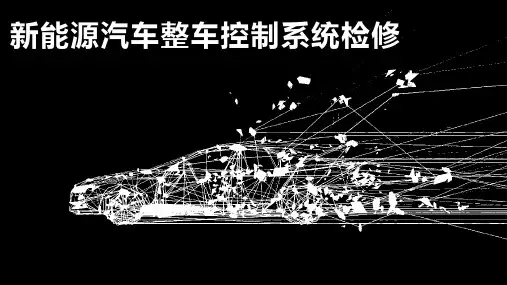
《新能源汽车整车控制系统检修》项目3 整车控制系统故障诊断与维修
3.1.1 整车控制器的主要输入信号
动力电池参数信号
电池管理系统可以将动力电池相关参数上 报整车控制器,由整车控制器控制动力电池的 充电功率和放电功率。
第 11 页 共 53 页
3.1 整车控制器信号输入电路的故障诊断与维修
1
信号输入电路故障诊断的一般步骤
3.1.2 整车控制器信号输入电路的故障诊断方法
第 21 页 共 53 页
3.2 整车控制器信号输出电路的故障诊断与维修
3.2.1 整车控制器的主要输出信号
1
冷却风扇控制信号
整车控制器通过控制两个风扇继电器的通断来控制两个冷却风扇的转动速度。
电 机 温 度 较 低 整车控制器将控制两个风扇继电器的线圈断电,使两个冷却风扇不转动。
电 机 温 度 较 高 整车控制器将控制其中一个风扇继电器的线圈通电,使两个冷却风扇低速转动。
水泵继电器ER04闭合,使电机水泵运转、冷却 液循环,进而降低驱动电机、车载充电机、电机 控制器的温度。
第 27 页 共 53 页
3.2 整车控制器信号输出电路的故障诊断与维修
3.2.1 整车控制器的主要输出信号
6
吉利帝豪 EV450 新能源汽车整车控制器的输出信号
3)驻车控制信号
控制过程为:
结合当前驱动电机转速及轮速情况判断是否符合驻车条件
3.1 整车控制器信号输入电路的故障诊断与维修
3.1.2 整车控制器信号输入电路的故障诊断方法
2
信号输入电路常见故障的检测
3)传感器功能故障及检测 以加速踏板位置信号的故障诊断与维修为例进行说明。
(1)故障现象。 (2)故障诊断步骤 (3)故障维修 (4)试车
第 16 页 共 53 页
新能源汽车整车控制器系统诊断规范
新能源汽车整车控制器系统诊断规范集团文件发布号:(9816-UATWW-MWUB-WUNN-INNUL-DQQTY-整车控制器系统诊断规范—“EV160”文件编号:“EV160”编制:校对:审核:“业务高级经理”会签:“控制系统集成主管”批准:“部长”XXX年XXX月版本信息目录1.参考文献“由网络工程师统一发布网络拓扑”Fig 1.C70GB-2014整车网络拓扑结构3.诊断接口Tab 1.OBD 诊断接口针脚定义“由线束工程师统一发布OBD接口定义”4.1.诊断协议4.1.1.物理层物理层应满足ISO11898-2要求及北京新能源汽车股份有限公司企业标准《新能源汽车高速 CAN 网络节点级电子控制单元( ECU)技术要求》要求。
4.1.2.数据链路层数据链路层应满足ISO11898-1要求。
所有诊断请求和应答帧的数据长度应为8字节,否则电控单元将忽略该诊断请求帧。
当诊断响应长度不足8字节时,空余的字节应用0xAA填充。
4.1.3.网络层网络层应满足ISO15765-2要求和下述要求:4.1.3.1.寻址方式可以支持物理寻址和功能寻址。
诊断消息ID描述见下表:Tab 2.诊断 ID列表“由网络工程师统一发布所有诊断ID分配,各系统填写各自的诊断ID至上表”4.1.3.2.网络层时间参数Tab 3.网络层时间参数需求4.1.4.应用层时间参数Tab 4.应用层时间参数需求4.2.Diagnostic Services(ISO14229-1)Services shall be implemented according to ISO14229-1. Additional details are specified in this section.4.2.1.Supported Diagnostic ServicesThe overview of ECU supported diagnostic services is described in the following table.权限。
新能源系统诊断规范标准
-/XXXX系统诊断规范—“填写项目代号”文件编号:“向项目申请编号”编制:校对:审核:“业务高级经理”会签:“控制系统集成主管”批准:“部长”XXX年XXX月版本信息目录版本信息 (2)1.参考文献 (5)2.网络拓扑 (5)3.诊断接口 (6)4.诊断需求 (7)4.1.诊断协议 (7)4.1.1.物理层 (7)4.1.2.数据链路层 (7)4.1.3.网络层 (7)4.1.4.应用层时间参数 (8)4.2.Diagnostic Services(ISO14229-1) (8)4.2.1.Supported Diagnostic Services (9)4.2.2.DiagnosticSessionControl(10H) (11)4.2.3.ECUReset (11H) (13)municationControl(28H) (14)4.2.5.SecurityAccess(27H) (15)4.2.6.TesterPresent(3EH) (21)4.2.7.ControlDTCSetting(85H) (21)4.2.8.ReadDataByIdentifier(22H) (23)4.2.9.WriteDataByIdentifier (2EH) (24)4.2.10.InputOutputControlByIdentifier (2FH) (26)4.2.11.ClearDiagnosticInformation (14H) (27)4.2.12.ReadDTCInformation (19H) (28)4.2.13.RoutineControl (31H) (35)4.2.14.RequestDownLoad(34H) (37)4.2.15.TransferData (36H) (37)4.2.16.RequestTransferExit (37H) (37)5.故障定义 (38)6.故障码DTC中英文对照表 (38)附录A: 冻结帧信息 (39)附录B: (41)B.1 版本信息参数列表: (41)B.2 数据流参数列表: (41)B.3 版本信息参数定义 (43)B.4 数据流参数定义 (45)1.参考文献2.网络拓扑“由网络工程师统一发布网络拓扑”Fig 1.C70GB-2014整车网络拓扑结构3.诊断接口Fig 2. OBD诊断接口Tab 1.OBD 诊断接口针脚定义“由线束工程师统一发布OBD接口定义”4.诊断需求4.1.诊断协议4.1.1.物理层物理层应满足ISO11898-2要求及北京新能源汽车股份有限公司企业标准《新能源汽车高速CAN 网络节点级电子控制单元(ECU)技术要求》要求。
新能源系统诊断规范
XXXX系统诊断规范—“填写项目代号”文件编号:“向项目申请编号”编制:校对:审核:“业务高级经理”会签:“控制系统集成主管”批准:“部长”XXX年XXX月版本信息目录版本信息........................................ 错误!未定义书签。
1.参考文献..................................... 错误!未定义书签。
2.网络拓扑..................................... 错误!未定义书签。
3.诊断接口..................................... 错误!未定义书签。
4.诊断需求..................................... 错误!未定义书签。
.诊断协议................................ 错误!未定义书签。
物理层............................ 错误!未定义书签。
数据链路层........................ 错误!未定义书签。
网络层............................ 错误!未定义书签。
应用层时间参数.................... 错误!未定义书签。
.Diagnostic Services(ISO14229-1)....... 错误!未定义书签。
Supported Diagnostic Services ..... 错误!未定义书签。
DiagnosticSessionControl(10H)... 错误!未定义书签。
ECUReset (11H) .................... 错误!未定义书签。
CommunicationControl(28H)....... 错误!未定义书签。
SecurityAccess(27H)............. 错误!未定义书签。
新能源系统诊断要求规范
实用文档XXXX系统诊断规范—“填写项目代号”文件编号:“向项目申请编号”编制:校对:审核:“业务高级经理”会签:“控制系统集成主管”批准:“部长”XXX年XXX月版本信息目录版本信息 (2)1.参考文献 (5)2.网络拓扑 (6)3.诊断接口 (7)4.诊断需求 (8)4.1.诊断协议84.1.1.物理层84.1.2.数据链路层84.1.3.网络层84.1.4.应用层时间参数94.2.Diagnostic Services(ISO14229-1)94.2.1.Supported Diagnostic Services94.2.2.DiagnosticSessionControl(10H)114.2.3.ECUReset (11H)14municationControl(28H)154.2.5.SecurityAccess(27H)174.2.6.TesterPresent(3EH)224.2.7................................. ControlDTCSetting(85H)234.2.8.ReadDataByIdentifier(22H)244.2.9.WriteDataByIdentifier (2EH)264.2.10.InputOutputControlByIdentifier (2FH)274.2.11.ClearDiagnosticInformation (14H)294.2.12.ReadDTCInformation (19H)304.2.13.RoutineControl (31H)384.2.14.................................. RequestDownLoad(34H)404.2.15.TransferData (36H)404.2.16.RequestTransferExit (37H)405.故障定义 (41)6.故障码DTC中英文对照表 (41)附录 A: 冻结帧信息 (42)附录 B: (44)B.1 版本信息参数列表: (44)B.2 数据流参数列表: (44)B.3 版本信息参数定义 (46)B.4 数据流参数定义 (48)1.参考文献2.网络拓扑“由网络工程师统一发布网络拓扑”Fig 1.C70GB-2014整车网络拓扑结构Fig 2.OBD诊断接口Tab 1.OBD 诊断接口针脚定义“由线束工程师统一发布OBD接口定义”4.1.诊断协议4.1.1.物理层物理层应满足ISO11898-2要求及北京新能源汽车股份有限公司企业标准《新能源汽车高速 CAN 网络节点级电子控制单元( ECU)技术要求》要求。
新能源系统诊断要求规范
实用标准文档XXXX系统诊断规范—“填写项目代号”文件编号:“向项目申请编号”编制:校对:审核:“业务高级经理”会签:“控制系统集成主管”批准:“部长”XXX年XXX月版本信息目录版本信息 (2)1.参考文献 (5)2.网络拓扑 (5)3.诊断接口 (6)4.诊断需求 (7)4.1.诊断协议 (7)4.1.1.物理层 (7)4.1.2.数据链路层 (7)4.1.3.网络层 (7)4.1.4.应用层时间参数 (8)4.2.Diagnostic Services(ISO14229-1) (8)4.2.1.Supported Diagnostic Services (9)4.2.2.DiagnosticSessionControl(10H) (11)4.2.3.ECUReset (11H) (13)municationControl(28H) (14)4.2.5.SecurityAccess(27H) (15)4.2.6.TesterPresent(3EH) (21)4.2.7.ControlDTCSetting(85H) (21)4.2.8.ReadDataByIdentifier(22H) (23)4.2.9.WriteDataByIdentifier (2EH) (24)4.2.10.InputOutputControlByIdentifier (2FH) (26)4.2.11.ClearDiagnosticInformation (14H) (27)4.2.12.ReadDTCInformation (19H) (28)4.2.13.RoutineControl (31H) (35)4.2.14.RequestDownLoad(34H) (37)4.2.15.TransferData (36H) (37)4.2.16.RequestTransferExit (37H) (37)5.故障定义 (38)6.故障码DTC中英文对照表 (38)附录A: 冻结帧信息 (39)附录B: (41)B.1 版本信息参数列表: (41)B.2 数据流参数列表: (41)B.3 版本信息参数定义 (43)B.4 数据流参数定义 (45)1.参考文献2.网络拓扑“由网络工程师统一发布网络拓扑”Fig 1.C70GB-2014整车网络拓扑结构3.诊断接口Fig 2. OBD诊断接口Tab 1.OBD 诊断接口针脚定义“由线束工程师统一发布OBD接口定义”4.诊断需求4.1.诊断协议4.1.1.物理层物理层应满足ISO11898-2要求及北京新能源汽车股份有限公司企业标准《新能源汽车高速CAN 网络节点级电子控制单元(ECU)技术要求》要求。
某新能源汽车整车控制器系统诊断规范
某新能源汽车整车控制器系统诊断规范某新能源汽车整车控制器系统诊断规范一、引言随着环境污染的日益严重以及能源补给的不稳定性,新能源汽车作为一种清洁、节能的交通工具,正逐渐走进人们的生活。
新能源汽车整车控制器系统作为其核心控制部件之一,对整个车辆的性能和安全起着至关重要的作用。
为了确保新能源汽车整车控制器系统的准确诊断和评估,制定本规范,以规范控制器系统的诊断流程和规范。
二、术语和定义1. 新能源汽车整车控制器系统:由控制器、传感器、执行器等组成的整个汽车控制系统。
2. 故障码:指在诊断系统中记录的表示控制器系统故障的编号。
3. 传感器:指用于感知汽车相关数据的部件,如油温传感器、转速传感器等。
4. 执行器:指用于执行命令的部件,如电动机、刹车执行器等。
5. 诊断流程:指针对控制器系统故障的诊断步骤和流程。
三、诊断规范1. 故障检测(1)车辆系统状态检测:通过传感器检测车辆各系统的工作状态,如电池电压、油温等。
(2)功能故障检测:通过对控制器系统功能进行测试,如电动机启动、行驶、刹车等。
(3)故障码读取:通过诊断工具读取控制器系统的故障码。
2. 故障诊断(1)故障码解读:根据故障码的具体含义,进行相应的故障诊断和确认。
(2)数据记录:在诊断过程中,对故障现象和相关数据进行记录,以便于分析和评估。
(3)实验验证:通过实验验证,确定故障的具体原因,如更换传感器、调整参数等。
3. 故障修复(1)根据诊断结果,进行相应的故障修复,如更换故障部件、调整参数等。
(2)修复后,重新测试控制器系统功能,确保故障得到有效修复。
(3)记录修复过程和结果,以便于后续分析和优化。
四、诊断工具1. 诊断工具应具备读取故障码、显示故障信息、进行实时数据监测等功能。
2. 诊断工具应支持标准的汽车通信协议,如CAN、LIN、FlexRay等。
3. 诊断工具应具备友好的用户界面和操作流程,便于操作人员进行诊断和修复。
五、安全性1. 在进行控制器系统诊断期间,要确保车辆和人员的安全,避免因操作不当导致的意外事故。
- 1、下载文档前请自行甄别文档内容的完整性,平台不提供额外的编辑、内容补充、找答案等附加服务。
- 2、"仅部分预览"的文档,不可在线预览部分如存在完整性等问题,可反馈申请退款(可完整预览的文档不适用该条件!)。
- 3、如文档侵犯您的权益,请联系客服反馈,我们会尽快为您处理(人工客服工作时间:9:00-18:30)。
北京新能源汽车股份有限公司整车控制器系统诊断规范—“EV160”文件编号:“EV160-20150002014”编制:校对:审核:“业务高级经理”会签:“控制系统集成主管”批准:“部长”XXX年XXX月版本信息目录版本信息 (2)1.参考文献 (5)2.网络拓扑 (5)3.诊断接口 (6)4.诊断需求 (7)4.1.诊断协议 (7)4.1.1.物理层 (7)4.1.2.数据链路层 (7)4.1.3.网络层 (7)4.1.4.应用层时间参数 (8)4.2.Diagnostic Services(ISO14229-1) (8)4.2.1.Supported Diagnostic Services (9)4.2.2.DiagnosticSessionControl(10H) (11)4.2.3.ECUReset (11H) (13)municationControl(28H) (14)4.2.5.SecurityAccess(27H) (15)4.2.6.TesterPresent(3EH) (21)4.2.7.ControlDTCSetting(85H) (21)4.2.8.ReadDataByIdentifier(22H) (23)4.2.9.WriteDataByIdentifier (2EH) (24)4.2.10.InputOutputControlByIdentifier (2FH) (26)4.2.11.ClearDiagnosticInformation (14H) (27)4.2.12.ReadDTCInformation (19H) (28)4.2.13.RoutineControl (31H) (35)4.2.14.RequestDownLoad(34H) (37)4.2.15.TransferData (36H) (37)4.2.16.RequestTransferExit (37H) (37)5.故障定义 (38)6.故障码DTC中英文对照表 (38)附录A: 冻结帧信息 (40)附录B: (42)B.1 版本信息参数列表: (42)B.2 数据流参数列表: (42)B.3 版本信息参数定义 (44)B.4 数据流参数定义 (46)1.参考文献2.网络拓扑“由网络工程师统一发布网络拓扑”Fig 1.C70GB-2014整车网络拓扑结构3.诊断接口Fig 2. OBD诊断接口管脚描述1 EVBUS CAN_H2 /Tab 1.OBD 诊断接口针脚定义“由线束工程师统一发布OBD接口定义”4.诊断需求4.1.诊断协议4.1.1.物理层物理层应满足ISO11898-2要求及北京新能源汽车股份有限公司企业标准《新能源汽车高速CAN 网络节点级电子控制单元(ECU)技术要求》要求。
4.1.2.数据链路层数据链路层应满足ISO11898-1要求。
所有诊断请求和应答帧的数据长度应为8字节,否则电控单元将忽略该诊断请求帧。
当诊断响应长度不足8字节时,空余的字节应用0xAA填充。
4.1.3.网络层网络层应满足ISO15765-2要求和下述要求:4.1.3.1.寻址方式可以支持物理寻址和功能寻址。
诊断消息ID描述见下表:Tab 2.诊断ID列表“由网络工程师统一发布所有诊断ID分配,各系统填写各自的诊断ID至上表”4.1.3.2.网络层时间参数Tab 3.网络层时间参数需求4.1.4.应用层时间参数Tab 4.应用层时间参数需求4.2.Diagnostic Services(ISO14229-1)Services shall be implemented according to ISO14229-1. Additional details arespecified in this section.4.2.1.Supported Diagnostic ServicesThe overview of ECU supported diagnostic services is described in the following table.Table 5 Supported diagnostic services of ECU说明:访问权限√1表示需要扩展安全级权限,√3表示需要编程安全级权限。
The services need to support suppressPositveResponseBit (SPRS) are showed in following table.The negativeResponseCodes (NRC) used by ECU are defined as follows:If two or more NRCs are reasonable, the ECU could send the negative responsemessage according to the following priority rules:•The 7Fh NRC have the highest priority;•For others, the NRC with smaller number has higher priority.4.2.2.DiagnosticSessionControl(10H)This service is used by the client to enable different diagnostic sessions in the server(s). A diagnostic session enables a specific set of diagnostic services in the server(s).4.2.2.1.Message FormatTiming P2server value is provided in 1ms resolution.Timing P2*server value is provided in 10ms resolution.4.2.2.2.Implementation RulesThis service is used by the diagnostic tool to enable different types of diagnostic sessions in a server. In order to execute a diagnostic service the appropriate session has to be started first.There shall be only one diagnostic session active at a time.Normal/Default Session (01h) shall be enabled automatically by the ECU if no diagnostic session has been requested at power up.The ECU shall return to Normal/Default Session (01h) after timeout of ExtendedDiagnostic Session.The ECU shall be capable of providing all diagnostic functionality defined for the default diagnostic session under normal operating conditions.The ECU shall first send a DiagnosticSessionControl Positive Response (50h xx) message before the new session becomes active in the ECU.A DiagnosticSessionControl Positive Response (50h xx) message shall be returned by an ECU if the diagnostic tool requests a session that is already running. If the ECU has already received the same request message previously and performed the requested operation, the ECU shall continue to perform the current operation (i.e. it is not a change of the session).The ECU shall remain in its current diagnostic session if it is not able to switch into the requested diagnostic session.The TesterPresent (3Eh) service shall be used to keep the non-default diagnostic sessions active by retriggering S3server. Also any other service request shall retrigger S3server.A functional TesterPresent (3Eh) request without response may be sent at any time, even regardless of any other service in progress.When receiving or transmitting any diagnostic messages, including 3Eh service,the S3servertimer will reset.Fig 3.Session transition diagram4.2.3.ECUReset (11H)This service requests the server to effectively perform an ECU reset based on the content of the ResetType parameter value (suppressPosRspMsgIndicationBit (bit 7) not shown).4.2.3.1.Message FormatByte Name Cvt Value(hex)#1 RequestServiceIdentifier M 11#2Sub-Function= [ResetType: HardResetSoftReset]M 0103 Positive Response:Byte Name Cvt Value #1 PositiveResponseServiceIdentifier M 51#2Sub-Function=[ResetType: HardResetSoftReset]M 0103 Negative Response:Byte Name Cvt Value#1 NegativeResponseServiceIdentifier M 7F#2 RequestServiceIdentifier M 11#3 NegativeResponseCode M NRCOption (Hex) Description Cvt 01 HardResetThis value identifies a “hard reset” condition which simulates t heM4.2.3.2.Implementation RulesThe positive response shall be sent before performing the ECU reset.The execution of reset will take <TBD> ms, which means the ECU can’t respond to any new request sent within this time.municationControl(28H)The service is used to “switch on/off” the transmission and/or the reception of certain messages of (a) server(s).4.2.4.1.Message Format4.2.4.2.Implementation RulesThere are no special general implementation rules for this service.4.2.5.SecurityAccess(27H)The purpose of this service is to provide a means to access data and/or diagnostic services, which have restricted access for security or safety reasons. Diagnostic services for downloading/uploading routines or data into a server and reading specific memory locations from a server are situations where security access may be required. Improper routines or data downloaded into a server could potentially damage the electronics or other vehicle components or risk the vehicle’s compliance to s afety, orsecurity standards. The security concept uses a seed and key relationship.The client shall request the server to unlock by sending the service SecurityAccess-RequestSeed message. The server shall respond by sending a seed. The seed is the input parameter for the key calculation algorithm. It is used by the client to calculate the corresponding key value.In a second step, the client shall request the key comparison by sending the calculated key to the server using the appropriate service SecurityAccess-SendKey. The server shall compare this key to one internally stored/calculated. If the two numbers match, then the server shall enable (unlock) the client’s access to specific services/data and indicate that with the service SecurityAccess-SendKey. If the two numbers do not match, this shall be considered as a false access attempt. If access is rejected for any other reason, it shall not be considered as a false access attempt. An invalid key requires the client to start over from the beginning with a SecurityAccess-RequestSeed message.If a server supports security, but is already unlocked when a SecurityAccess-RequestSeed message is received, that server shall respond with a SecurityAccess-RequestSeed positive response message service with a seed value equal to zero (0). The client shall use this method to determine if a server is locked by checking for a non-zero seed.The Seed-Key algorithmfor SecurityAccess(Mandatory):Key = ((((seed>>4) XOR seed)<<3) XOR seed)。