SLK智能流量开关
图尔克FCS-G1流量开关
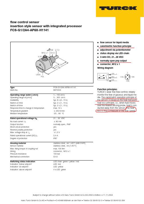
Hans Turck GmbH & Co.KG • Postfach • D-45466 Mülheim an der Ruhr • Telefon 02 08/49 52-0 • Telefax 02 08/49 52-264Subject to change without notice • © Hans Turck GmbH & Co.KG 2002 • Edition: • 11.11.2004flow control sensorinsertion style sensor with integrated processorFCS-G1/2A4-AP8X-H1141●flow sensor for liquid media ●calorimetric function principle ●adjustment via potentiometer ●status display via LED chain ●3-wire DC, 21...26 VDC ●normally open pnp output ●connector, M12 x 1Wiring diagramFunction principlesTURCK's wear-free flow controls reliably monitor the flow of gaseous and liquid me-dia. The calorimetric operation principle of the sensors is based on the heat transport/heat loss principle, i.e., when fluid movesover the heated sensing probe, heat is con-ducted away from the sensor. The heat loss is thus a measure of the flow speed.Type FCS-G1/2A4-AP8X-H1141Ident-No.6870004Operating range water [ cm/s] 1... 150 cm/s Operating range oil [cm/s] 3... 300 cm/s Availabilitytyp. 8 s (2...15 s)Switch-on time typ. 2 s (1...15 s)Switch-off timetyp. 2 s (1...15 s)Response time to change in temperature max. 12 s Temperature gradient ≤ 250 K/min Medium temperature-20... 80 °C Rated operational voltage U B 21... 26 VDC No-load current I 0 ≤ 80 mAOutput functionnormally open, PNP Short-circuit protection yes Reverse polarity protection yes Max. voltage drop at I e ≤ 1,5 V Rated operational current (DC) I e 0,4 ADegree of protectionIP67Housing material stainless steel, A4 1.4571 (AISI 316Ti)Sensor materialstainless steel, A4 (1.4571)Max. fixing torque of coupling nut max. 100 NmWiringconnector, M12 x 1Pressure resistance 100 bar Mechanical connection G1/2Switching status indication LED chain green / yellow / red Indication 'below setpoint' LED red Indication 'at setpoint' LED yellow Indication 'above setpoint'4 x LED green。
使用说明书安全开关SLK
开关状态
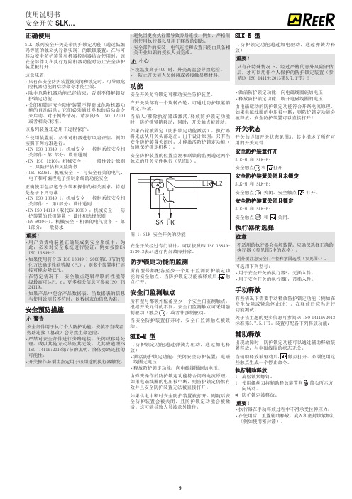
开关的详细开关状态见图3。其中描述了所有可 用的开关元件 安全防护装置打开 SLK-M 和 SLK-E: 安全触点 和 打开 安全防护装置关闭且未锁定 SLK-M 和 SLK-E: 安全触点 关闭。安全触点 打开。 安全防护装置关闭且锁定 SLK-M 和 SLK-E: 安全触点 和 关闭。
执行器的选择
关部件–第1部分:设计通则 ffEN ISO 12100,机械安全 – 一般性设计原则
– 风险评估和风险降低 ffIEC 62061,机械安全 – 与安全有关的电气、
电子和可编程电子控制系统的功能安全
正确使用包括遵守安装和操作的相关要求,特别 是基于下列标准 ffEN ISO 13849‑1,机械安全 - 控制系统安全相
关部件 – 第1部分:设计通则 ffEN ISO 14119(取代EN 1088),机械安全 – 防
护装置的联锁装置 - 设计和选择原则 ffEN 60204-1,机械安全 - 机器的电气设备 – 第
1部分:一般要求
重要! ff用 户 负 责 将 装 置 正 确 集 成 到 安 全 系 功能通过加电驱动,通过弹簧力释 放)
重要!
只有在特殊情况下,经过严格的意外风险评估 后,才可以用作个人保护的防护锁定装置(参 见EN ISO 14119:2013第5.7.1节)!
ff激活防护锁定功能:向电磁线圈施加电压 ff释放防护锁定功能:断开电磁线圈的电压
由电磁驱动的防护锁定功能符合开路电流原理。 如果电磁线圈的电压被中断,则防护锁定功能会 被释放,安全防护装置可以直接打开!
E1 E2
SK ÜK
图 1: SLK 安全开关的功能
安全开关经过专门设计,可以按照EN ISO 13849 2:2013表A4进行内部故障排除。
SLMC 数显流量开关集成型说明书 - PF2M7##系列

Instruction ManualPF2M7## seriesThe intended use of the digital flow switch is to monitor and display flow information.These safety instructions are intended to prevent hazardous situations and/or equipment damage. These instructions indicate the level of potential hazard with the labels of “Caution,” “Warning” or “Danger.”They are all important notes for safety and must be followed in addition to International Standards (ISO/IEC) *1), and other safety regulations. *1)ISO 4414: Pneumatic fluid power - General rules relating to systems. ISO 4413: Hydraulic fluid power - General rules relating to systems.IEC 60204-1: Safety of machinery - Electrical equipment of machines. (Part 1: General requirements)ISO 10218-1: Manipulating industrial robots -Safety. etc.∙ Refer to product catalogue, Operation Manual and Handling Precautions for SMC Products for additional information. ∙ Keep this manual in a safe place for future reference.∙ This product is class A equipment intended for use in an industrial environment. There may be potential difficulties in ensuring electromagnetic compatibility in other environments due to conducted or radiated disturbances.CautionCaution indicates a hazard with a low level of risk which, ifnot avoided, could result in minor or moderate injury.WarningWarning indicates a hazard with a medium level of riskwhich, if not avoided, could result in death or serious injury.DangerDanger indicates a hazard with a high level of risk which, ifnot avoided, will result in death or serious injury.Warning∙ Always ensure compliance with relevant safety laws and standards.∙ All work must be carried out in a safe manner by a qualified person in compliance with applicable national regulations.∙ Do not disassemble, modify (including changing the printed circuit board) or repair. An injury or failure can result.∙ Do not operate the product outside of the specifications. Fire, malfunction or damage to the product can result.∙ Do not operate in an atmosphere containing flammable, explosive or corrosive gas.Fire or an explosion can result.∙ Do not use the product for flammable fluids. Fire, explosion, damage or corrosion can result. ∙ If using the product in an interlocking circuit:Provide a double interlocking system, for example a mechanical system.∙ Check the product for correct operation.Otherwise malfunction can result, causing an accident.∙ Do not use the product in a place where static electricity is a problem.Product failure or system malfunction may result.Otherwise electric shock, malfunction or product damage can result. ∙ Refer to the operation manual on the SMC website (URL: https:// ) for more safety instructions.2 SpecificationsWarningSpecial products (-X) might have specifications different from those shown in this section. Contact SMC for specific drawings.3.1 PF2M7## (with flow adjustment valve)ItemDescriptionSocket Socket for electrical connections.Piping port Connected to the fluid inlet IN side and to the fluid outlet OUT side.Flow adjustment valve Orifice mechanism to adjust the flow. Lock ring Used to lock the flow adjustment valve.Mounting hole Used to mount the product on a DIN rail or directly to a panel.BodyThe body of the product.Lead wire and connector Lead wire to supply power and output signals.3.2 DisplayItem DescriptionUP buttonSelects the mode or increases the ON/OFF set value. Press this button to change to the peak display mode.DOWN button Selects the mode or decreases the ON/OFF set value.Press this button to change to the bottom displaymode.Main displayDisplays the flow value, setting mode, and error indication.Four display modes can be selected: display always in red or green, or display changing from green to red, or red to green, according to the output status (OUT1). SET button Press this button to change to another mode and to set a value.Output display (Operation LED) Displays the output status of OUT1 and OUT2. OUT1: LED is ON (Orange) when the output is ON. OUT2: LED is ON (Orange) when the output is ON. When the accumulated pulse output mode is selected, the output display is OFF.Units display Arbitrary units are ON based on the flow display setting (instantaneous or accumulated flow)IO-Link status indicator light LED is ON when OUT1 is used in IO-Link mode. (LED is OFF in SIO mode)ORIGINAL INSTRUCTIONSModel 701 702 705 710 725 750 711 721 F l u i dApplicable fluidDry air, N 2, Ar, CO 2(ISO8573-1 1.1.2 to 1.6.2)Fluid temperature range 0 to 50 o CF l o w r a t e Detection method Thermal(main flow) Thermal (branch flow) R a t e d f l o w r a n g e [L /m i n ] Dry air,N 2,Ar 0.01 to 1 0.02 to 2 0.05 to 5 0.1 to 10 0.3 to 25 0.5 to 50 1 to 100 2 to200CO 20.01 to 0.5 0.02 to 1 0.05 to 2.5 0.1 to 5 0.3 to 12.5 0.5 to 25 1 to 50 2 to100S e t f l o w r a n g e Instantaneous flow [L/min]-0.05 to 1.05 -0.1 to 2.1 -0.25 to 5.25 -0.5 to 10.5 -1.3 to 26.3 -2.5 to 52.5 -5 to 105 -10 to 210Accumulated flow [L] 0.00 to 9999999.99 0.0 to 99999999.9 0 to 999999999 M i n . s e t t i n g u n i t Instantaneous flow [L/min] 0.001 0.01 0.1 1Accumulatedflow [L]0.01 0.1 1 Accumulatedvolume [L/pulse]0.01 0.1 1 Accumulated value hold Select from 2 and 5 minutesP r e s s u r eOperating pressure range-0.1 to 0.75 MPa Rated pressurerange-0.07 to 0.75 MPaProof pressure 1.0 MPa Pressure loss Refer to the pressure loss graph. Pressure characteristics ±5%F.S. ±1 digit (0.35 MPa standard)E l e c t r i c a l P o w e r s u p p l y v o l t a g e Switch output device 12 to 24 VDC ±10% IO-Link device18 to 30 VDC ±10% Currentconsumption 35 mA or less ProtectionPolarity protection A c c u r a c yDisplay accuracy ±3% F.S. ±1 digitAnalogue output accuracy ±3% F.S.Repeatability ±1%F.S. ±1 digit(±2% F.S. ±1 digit when digital filter is set to 0.05 s) Temperature characteristics ±3%F.S. ±1 digit (15 to 35 oC: 25 oC standard) ±5%F.S. ±1 digit (0 to 50 o C: 25 o C standard) S w i t c h o u t p u tOutput type NPN or PNP open collectorOutput mode Select from hysteresis mode, window comparator mode, accumulated output mode, accumulated pulse output mode, error outputand switch output OFFSwitch operation Select from normal output and reversed outputMaximum load current80 mA Maximum applied voltage 28 VDC (NPN only)I n t e r n a l v o l t a g e d r o pStandard valueNPN: 1 V or less (Load current 80 mA) PNP: 1.5 V or less (Load current 80 mA) IO-Link compatible product 1.5 V or less (Load current 80 mA) Response time 50 ms or lessDelay time 0 to 0.10 s (0.01 s increment), 0.1 to 1.0 s (0.1 s increment), 1 to 10 s (1 s increment)Select from 20 s, 30 s, 40 s, 50 s, 60 sHysteresis VariableProtectionShort circuit protectionModel 701 702 705 710 725 750 711 721 A n a l o g u e o u t p u tOutput type Voltage output: 1 to 5 V (or 0 to 10 V),Current output 4 to 20 mAI m p e d a n c e Voltage outputOutput impedance approx.1 kΩ CurrentoutputMax. load impedance Power supply voltage 24 V: 600 Ω Power supply voltage 12 V: 300 Ω Response time 50 ms ±40% D i s p l a yReference conditionSelect from normal condition (NOR) andstandard condition (STD) Display mode Select from instantaneous flow andaccumulated flow U n i t InstantaneousflowL/min, cfm Accumulated flowL, ft 3 D i s p l a y a b l e r a n g e Instantaneous flow [L/min]-0.05 to 1.05 -0.1 to 2.1 -0.25 to 5.25 -0.5 to 10.5 -1.3 to 26.3 -2.5 to 52.5 -5 to 105 -10 to 210 Zero cut-off range 0 to ±10%F.S. (selected for every 1%F.S. of max. rated flow rate) Accumulated flow [L] 0.00 to 9999999.99 0.0 to99999999.9 0 to 999999999Display Display type: LCD, Display colour: Red, green,Display digit: 7-segment, 4 digits Operation LED LED is ON when switch output is ON,OUT1/OUT2: Orange Digital filterSelect from 0.05 s, 0.1 s, 0.5 s, 1 s, 2 s and 5 s E n v i r o n m e n t a l r e s i s t a n c eEnclosure IP40 Withstand voltage 1000 VAC, 1 min. between terminals andhousing Insulation resistance 50 MΩ or longer (with 500 VDC) between terminals and housing Operatingtemperature rangeOperation: 0 to 50 o C, Storage: -10 to 60 o C(no freezing or condensation)Operating humidity range Operation, Storage: 35 to 85%R.H. (no freezing or condensation) P i p i n gP i p i n g s p e c i f i c a t i o n One-touch fitting C4 (ϕ4) / C6 (ϕ6)C6 (ϕ6) / N7 (ϕ1/4”) C8 (ϕ8) / N7 (ϕ1/4”)Screw fitting (Rc/NPT/G) 01 (Rc1/8) N1 (NPT1/8) F1 (G1/8)02 (Rc1/4) N2 (NPT1/4) F2 (G1/4)Port direction Straight, RearMaterial fluid contact parts PPS, PBT, FKM, SUS304, brass (electrolessnickel plating), Si, Au, GE4FW e i g h tB o d y One-touch fitting Straight: 40 g Rear: 55 g 48 g 63 g Screw fittingStraight: 60 g Rear: 75 g 72 g 87 gFlow adjustment valve -+34 g Lead wire +35 g Bracket +20 g Panel mount adapter +15 g DIN rail mounting bracket +65 gThe product code is displayed for approximately 3 seconds afterpower is supplied.Then measurement mode will be displayed and the switchoperation will start.4.1 InstallationWarning∙Do not install the product unless the safety instructions have been readand understood.∙Use the product within the specified operating pressure andtemperature range.∙Proof pressure could vary according to the fluid temperature. Checkthe characteristics data for operating pressure and proof pressure.4.2 EnvironmentWarning∙Do not use in an environment where corrosive gases, chemicals, saltwater or steam are present.∙Do not use in an explosive atmosphere.∙Do not expose to direct sunlight. Use a suitable protective cover.∙Do not install in a location subject to vibration or impact in excess ofthe product’s specifications.∙Do not mount in a location exposed to radiant heat that would result intemperatures in excess of the product’s specifications.∙Refer to the flow direction of the fluid indicated on the product forinstallation and piping.∙Do not mount the body with the bottom facing upwards.Retention of air can cause inability to measure accurately.∙Do not insert metal wires or other foreign matter into the piping port.This can damage the sensor causing failure or malfunction.∙Never mount a product in a location that will be used as a foothold.The product may be damaged if excessive force is applied by steppingor climbing onto it.∙If there is a risk of foreign matter entering the fluid, install and pipe afilter or mist separator at the inlet to avoid failure and malfunction.Otherwise damage or malfunction can result.4.3 Panel mounting∙Insert panel mount adapter B (supplied as an accessory) into sectionA of the panel mount adapter.Push panel mount adapter B from behind until the display is fixed ontothe panel.The bracket pin engages the notched part of panel adapter section Cto fix the display.∙The switch can be mounted on a panel with a thickness of 1 to 3.2 mm.4.4 Bracket mounting∙Mount the bracket using the mounting screws supplied.∙The required tightening torque is 0.42 ±0.04 N•m.∙Install the product (with bracket) using the M3 screws (4 pcs.).∙Bracket thickness is approximately 1.2 mm.4.5 DIN rail mounting (using ZS-33-R#)∙Mount the DIN rail mounting parts using the mounting screws and jointscrews supplied.∙The required tightening torque of the DIN rail mounting screws and∙Refer to the operation manual on the SMC website(URL: https://) for all mounting dimensions.4.6 PipingCaution∙Before connecting piping make sure to clean up chips, cutting oil, dust etc.∙Ensure there is no leakage after piping.∙Any dust left in the piping should be flushed out by air blow beforeconnecting piping to the product.Otherwise damage or malfunction can result.∙For piping of the product, hold the piping with a wrench on the metalpart of the product.Holding other parts of the product with a wrench may damage the product.4.7 WiringCaution∙Do not perform wiring while the power is on.∙Confirm proper insulation of wiring.∙Do not route wires and cables together with power or high voltage cables.Otherwise the product can malfunction due to interference of noise andsurge voltage from power and high voltage cables to the signal line.∙Keep wiring as short as possible to prevent interference fromelectromagnetic noise and surge voltage. Do not use a cable longerthan 30 m. When using it as an IO-Link device, do not use a cablelonger than 20 m.∙Ensure that the FG terminal is connected to ground when using acommercially available switch-mode power supply.∙When the analogue output is used, install a noise filter (line noise filter,ferrite element, etc.) between the switch-mode power supply and thisproduct.Connecting / Disconnecting∙When mounting the connector, insert it straight into the socket, holdingthe lever and connector body, and push the connector until the leverhooks into the housing, and locks.∙When removing the connector, press down the lever to release thehook from the housing and pull the connector straight out.Connector pin numbers (on the lead wire)•Lead wire and connector (ZS-33-D)No. Signal name Lead wire colour1 DC(+) Brown2 OUT2 White3 OUT1 Black4 DC(-) Blue•M12 conversion lead wire (ZS-33-DM)Used as switch output deviceNo. Signal name Lead wire colour1 DC(+) Brown2 N.C./OUT2 White3 DC(-) Blue4 OUT1 BlackUsed as IO-Link deviceNo. Signal name Lead wire colour1 L+Brown2 N.C./OUT2 White3 L-Blue4 C/Q BlackPower is supplied*: The outputs will continue to operate during setting.*: Simple setting mode and function selection mode settings arereflected each other.6 Flow Setting6.1 Switch operationWhen the flow exceeds the set value, the switch will be turned ON.When the flow falls below the set value by the amount of hysteresis ormore, the switch will be turned OFF.The default setting is to turn on the flow switch when the flow reaches thecentre of the upper limit of the rated flow range.If the operation shown below is acceptable, keep this setting.*: For hysteresis refer to [F 1] Setting of OUT1 and [F 2] Setting of OUT2.Without flow adjustmentvalve (using ZS-33-M)With flow adjustment valve(using ZS-33-MS)Press the SETbutton for 5seconds or longerPress the SETbutton between2 to 5 secondsPress the SETbutton onceFlow Setting andHysteresis(Simple settingmode)Function Setting(Functionselection mode)Other Settings∙Snap shot∙Key-lock∙Zero clear[Simple setting mode (Hysteresis mode)]In the Simple setting mode, the set value and hysteresis can be changed. (1) Press the SET button once in measurement mode.[P_1] or [n_1] and the [current set value] are displayed alternately.(2) Change the set value using the UP or DOWN button and press theSET button to set the value. Then, the setting moves to hysteresis setting (The snap shot function can be used). ∙ Press the UP button continuously to keep increasing the set value.∙ Press the DOWN button continuously to keep decreasing the set value.(3) [H_1] and the current set value are displayed in turn.(4) Change the hysteresis by pressing the UP or DOWN button and press the SET button. Setting is completed and the product returns to measurement mode (The snap shot function can be used).* For models with switch outputs for both OUT1 and OUT2, [P_2] or [n_2] will be displayed. These are set simultaneously.* After enabling the setting by pressing the SET button, it is possible to return to measurement mode by pressing the SET button for 2 seconds or longer.* When hysteresis mode is not used, "Input set value” is displayed. * The set value and hysteresis settings limit each other.* For more detailed setting, set each function in function selection mode.8.1 Function selection modeIn measurement mode, press the SET button for 2 to 5 seconds to display [F 0] on the display.Select to display the function to be change [F ].Press the SET button for 2 seconds or longer in function selection mode to return to measurement mode. *: Some products do not have all the functions. If a function is not available or selected due to configuration of other functions, [- - -] is displayed.8.2 Default settings*: Setting is only possible for models with the units selection function. *: Only available for models with switch outputs for both OUT1 and OUT2.*: This function is available for models with analogue output. Analogue free span function can be selected.*: This function is available in IO-Link compatible products. *: This function is available for models with external input.9 Other Settings∙ Snap shot function∙ Peak/bottom value indication ∙ Reset∙ Key-lock function ∙Zero clear functionRefer to the operation manual on the SMC website(URL: https:// ) for setting these functions.10.1 General MaintenanceCaution∙ Not following proper maintenance procedures could cause the product to malfunction and lead to equipment damage.∙ If handled improperly, compressed air can be dangerous.∙ Maintenance of pneumatic systems should be performed only by qualified personnel.∙ Before performing maintenance, turn off the power supply and be sure to cut off the supply pressure. Confirm that the air is released to atmosphere.∙ After installation and maintenance, apply operating pressure and power to the equipment and perform appropriate functional and leakage tests to make sure the equipment is installed correctly.∙ If any electrical connections are disturbed during maintenance, ensure they are reconnected correctly and safety checks are carried out as required to ensure continued compliance with applicable national regulations.∙ Do not make any modification to the product.∙ Do not disassemble the product, unless required by installation or maintenance instructions.∙ How to reset the product after a power cut or when the power has been unexpectedly removedThe settings of the product are retained from before the power cut or de-energizing.The output condition also recovers to that before the power cut or de-energizing, but may change depending on the operating environment. Therefore, check the safety of the whole system before operating the product.11 How to OrderRefer to drawings/catalogue on the SMC website (URL: https:// ) for ‘How to Order’ information.12 Outline Dimensions (mm)Refer to the operation manual on the SMC website(URL: https:// ) for outline dimensions.ItemDefault setting[F 0] [FLU] [FLU] Select the flow rate[Air] Dry air, N 2[rEF] Setting the unitscriteria [Std] Standard condition [Unit] Measurement unitsetting [ L] L/min (L) [norP] Switch output PNP/NPN setting [PnP] PNP output [i_o] SW / external input setting[oUt] SW output [F 1] [oUt1][oUt1] Setting of OUT1[HYS] Hysteresis mode[1ot] OUT1 outputconfiguration setting [1_P] Normal output[P_1] Set value [ ] 50% of maximum rated flow PF2M701: 0.5 L/min, PF2M702: 1.0 L/minPF2M705: 2.5 L/min, PF2M710: 5 L/minPF2M725: 12.5 L/min, PF2M750: 25 L/minPF2M711: 50 L/min PF2M721: 100 L/min[H_1] Hysteresis [ ] 5% of maximum rated flow PF2M701: 0.05 L/min,PF2M702: 0.1 L/minPF2M705: 0.25 L/min,PF2M710: 0.5 L/min PF2M725: 1.3 L/min, PF2M750: 2.5 L/minPF2M711: 5 L/min PF2M721: 10 L/min[dt1] Delay time setting [0.00] 0.00 s [CoL] Display colour setting [1SoG] ON: Green OFF: Red[F 2][oUt2][oUt2] Setting of OUT2[HYS] Hysteresis mode[2ot] OUT2 outputconfiguration setting [2_P] Normal output[P_2] Set value [ ] 50% of maximum rated flow PF2M701: 0.5 L/min,PF2M702: 1.0 L/min PF2M705: 2.5 L/min,PF2M710: 5 L/min PF2M725: 12.5 L/min,PF2M750: 25 L/minPF2M711: 50 L/minPF2M721: 100 L/min [H_2] Hysteresis [ ] 5% of maximum rated flow PF2M701: 0.05 L/min,PF2M702: 0.1 L/min PF2M705: 0.25 L/min,PF2M710: 0.5 L/min PF2M725: 1.3 L/min,PF2M750: 2.5 L/minPF2M711: 5 L/minPF2M721: 10 L/min [dt2] Delay time setting [0.00] 0.00 s [CoL] Display colour setting[1SoG] ON: Green OFF: Red[F 3] [FiL] [FiL] Digital filter setting [1.0] 1.0 s [F 4] [PrS] [PrS] Auto-preset function setting [oFF] Manual Item Default setting[F10] [FLo] [FLo] Display mode [inS] Instantaneous flow [F11] [drE] [drE] Display resolutionsetting [1000] 1000-split [F13] [rEv] [rEv] Reverse display[oFF] Not reverse[F14] [CUt] [CUt] Zero cut-off setting[1.0] 1% of maximum rated flow PF2M701: 0.01 L/min, PF2M702: 0.02 L/min PF2M705: 0.05 L/min, PF2M710: 0.1 L/min PF2M725: 0.3 L/min, PF2M750: 0.5 L/min PF2M711: 1 L/min PF2M721: 2 L/min[F20] [inP] [inP] External input setting [rAC] Accumulated value reset[F22] [AoUt] [AoUt] Analogue output setting [1-5] 1 to 5 V Voltage output(when voltage is output) [---] Analogue output is notselectable(for current type output)[F30] [SAvE] [SAvE] Accumulated flowvalue hold setting[oFF] Not held [F80] [diSP] [diSP] Display OFF modesetting[ on] Normal display [F81][Pin] [Pin] Security code [oFF] Unused[F90] [ALL][ALL] Setting of allfunctions[oFF] Unused[F96] [S_in][S_in] External input signalcheck No setting due to input signal setting[F98][tESt] [tESt] Output checking[ n] Normal output [F99] [ini][ini] Reset to the defaultsettings[oFF] Not recover13.1 Error indicationIf the error cannot be reset after the above measures are taken, or errors other than above are displayed, please contact SMC.Refer to the operation manual on the SMC website (URL: https://) for more detailed information about troubleshooting. 14.1 Limited warranty and Disclaimer/Compliance RequirementsRefer to Handling Precautions for SMC Products.15 Product disposalThis product should not be disposed of as municipal waste. Check yourlocal regulations and guidelines to dispose this product correctly, in orderto reduce the impact on human health and the environment.16 ContactsRefer to or www.smc.eu for contacts.URL: https:// (Global) https://www.smc.eu (Europe)SMC Corporation, 4-14-1, Sotokanda, Chiyoda-ku, Tokyo 101-0021, JapanSpecifications are subject to change without prior notice from the manufacturer.© 2021SMC Corporation All Rights Reserved.Template DKP50047-F-085M。
SLK-M200-LTE说明书
SMA母头接口
串口
RS232-DB9接口
USB
USB2.0接口
电源
Supply voltage range: 5~35V DC
尺寸
75*51*16MM
指示灯
Power(只要通电此灯就会常亮)
DATA(正确插入SIM卡,注册到网络之后快闪)
RING(有来电闪烁,无来电灭)
短消息:
SMS
• Point to point MO and MT
SLK-M200-LTE说明书
产品简介:
LTE Modem,也叫做LTE调制解调器,它是一种实现LTE(分组交换)通信的调制解调的设备,它是在随着无线数据业务的快速发展,越来越多的设备开始要求具备无线通讯能力的这种背景下诞生的。许多从来没有的应用从理想变成了现实,如无线上网、远程监控﹑远程数据采集等。
•TD-SCDMA B34/B39
•UMTS/HSDPA/HSPA+ B1/B8
•CDMA 1X/EVDO BC0
•GSM/GPRS/EDGE 900/1800 MHz
SLK-M200-LTE-H(EU)
欧洲版本
•FDD-LTE B1/B3/B5/B7/B8/B20
•Dual-Band UMTS/HSDPA/HSPA+ B1/B5/B8
•Dual-Band UMTS/HSDPA/HSPA+
B1/B5
速率(理论速度,实际与当地运营商有关系)
速率
•LTE CAT4
- Uplink up to 50Mbps
- Downlink up to 150Mbps
•HSPA+
- Uplink up to 5.76 Mbps
工业流量开关参数
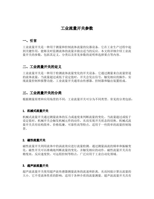
工业流量开关参数一、引言工业流量开关是一种用于测量和控制流体流量的仪器设备。
它在工业生产过程中起到关键作用,能够及时监测流体的流量并做出适当的反应。
本文将详细介绍工业流量开关的参数,包括其定义、分类以及常见参数的说明和选择要点等内容。
二、工业流量开关的定义工业流量开关是一种用于检测流体流量变化的开关设备。
它通过测量来自流量管道的流体流量,当流量超过或低于设定值时,开关会发出信号,触发相应的操作,实现流量控制和报警功能。
工业流量开关通常由传感器、控制器和输出装置组成。
三、工业流量开关的分类根据测量原理和应用场景的不同,工业流量开关可分为不同类型。
常见的分类包括:1. 机械式流量开关机械式流量开关通过测量流体的压力或速度来判断流量的变化。
当流量超过或低于设定值时,机械开关会触发机械元件的动作,从而实现开关状态的切换。
机械式流量开关具有结构简单、价格低廉、可靠性高等特点,适用于一些简单的流量控制场景。
2. 磁性流量开关磁性流量开关利用流体中的涡流效应进行流量检测。
通过测量涡流的频率和振幅变化,磁性开关可以准确地判断流量的变化,并触发相应的动作。
磁性流量开关具有精度高、反应速度快、可远程控制等特点,广泛应用于工业自动化领域。
3. 超声波流量开关超声波流量开关使用超声波传感器测量流体的流速和距离,从而间接计算出流量的大小。
它不受流体性质的影响,适用于各种介质的流量测量。
超声波流量开关具有非接触式测量、高精度和可靠性高等特点,在化工、石油、医药等行业得到广泛应用。
四、工业流量开关的常见参数工业流量开关的性能参数对于选择合适的开关设备至关重要。
以下是常见的工业流量开关参数的解释和选择要点:1. 测量范围测量范围是指工业流量开关可以正常测量的流量范围。
该参数决定了开关的适用场景,选择时应根据实际需求确定。
2. 精度精度是工业流量开关测量值与真实值之间的偏差。
较高的精度可以提高测量的准确性,但通常也意味着更高的成本。
开利流量开关的工作原理

开利流量开关的工作原理
开利流量开关是一种用于控制液体或气体流动的装置。
它的工作原理主要基于液体或气体的流动压力和流速。
开利流量开关内部通常有一个弹簧,一个可变阻尼器和一个浮子。
弹簧用于保持流量开关的状态,使其在正常工作时处于关闭状态。
可变阻尼器用于根据流体流速调节浮子的位移,从而控制开关的状态。
当流体流动通过流量开关时,流体的流速会引起浮子随之移动,浮子的位移会改变浮子上附加的磁棒和磁场传感器之间的相对位置。
当浮子移动到某个特定位置时,磁棒会接触到磁场传感器,从而改变磁场传感器的状态。
磁场传感器的状态变化会被传输给控制器,控制器根据接收到的信号决定是否打开或关闭流量开关。
当流速超过预设值时,浮子位移将足够大以使磁棒接触到磁场传感器,此时控制器将开启流量开关。
相反,当流速低于预设值时,浮子的位移将不足以使磁棒接触到磁场传感器,此时控制器将关闭流量开关。
综上所述,开利流量开关的工作原理主要是通过测量流体流速,根据测量结果控制浮子位移并改变磁棒与磁场传感器之间的相对位置,从而实现开关的打开和关闭。
管道式流量开关SLGK
管道式流量开关SLGK
品牌:北方华瑞
型号:SLGK
SLGK系列管道式流量开关(防爆)
【SLGK系列管道式流量开关(防爆)】基本性能及应用
适用介质:气体、液体、蒸汽
小流量适用,两组SPDT开关输出
不适用介质:浆液及高粘度介质
》适用于化学介质,多种材质及衬里可选
》适用于小管径和低流速
》有就地型、远传型、夹套型、防爆、耐腐等多种形式
详细技术参数
概述
SLGK流量开关,可对各种液体流量进行监测和发讯控制,独特的流线型结构设计、准确度稳定的性能,被广泛应用于管道中流量的监测及各种大、中、小型设备的冷却、润滑系统中。
例如:发电机组、电动机、轧机、压缩机、传送系统等,当流量超过您设置的预置开关点时,它可以输出一个控制信号,这个预置开关点可以设置在量程中的任何一个位置,开关点在安装后的条件下,也可以很方便的进行调整。
技术参数
口径:DN15~DN150 (1/2"至6")
精度:1.5%FS
重复性:±2.5%
温度:标准≤85℃,
最大≤300℃
压力等级:0.6-4.0 MPa(高压可选)
信号输出:报警点输出可配套晶体管继电器使用(本安型)。
Honsberg流量开关
解决方案
使用直列活塞式设计的流量开关 HD1K、HR1MV, 使用流量 进行准确监测。 可选多种外型的现场指示表盘。 使用旋钮或滑块就能轻松完成开关点设置,适用于液压润滑 行业。 直列活塞式 HD1K
直列活塞式 HD1K、HRIMV
为客户定制非标型号 , 满足更多要求 可选防爆型号 特别耐脏 , 适用于恶劣环境 Pn 最高达 500bar,温度最高 120℃ 可配智能集成系统 (omni, Flex, EFFI 等) , 现场数字显示, 输出模拟信号、开关量信号。
齿轮流量计 VHZ-...GA...
精确测量高粘度液体 PN200,-25...80℃ 任意安装 无磁性部件 可选铝或不锈钢外壳 模拟信号输出 , 显示 , 开关点 , 适配其他 的变送系列 ( 如 omni, Flex, EFFI…) VHZ 系列齿轮流量计
案例客户名单
上海外高桥电厂 盘山电厂 OMNI 系列集成系统磨煤机润滑
客户困扰
润滑油粘度大。如何精确测量 ? 流量计信号需要连入 DCS 系统 , 需要标准电流 信号。如何解决? 现场工人需要查看实时流量大小。如何解决?
解决方案
选择容积测量来计算流量的齿轮式流量计可以 精确测量润滑油 , 忽视粘度的影响。 可选配集成系统 Omni,满足客户更多使用要 求。可变送输出标准电流信号、现场数字显示、 还可设置 2 个开关点。
PN 25 25 25 25 25 16 16 16 16 16
开关值 l/min H2O 固定开关选择范围 1-10 1-10 4-20 10-40 20-60 30-100 50-150 100-200 180-330 300-600
L mm 150 150 150 150 150 156 156 156 156 156
IO-Link数字流量开关操作手册说明书
Before UseDigital Flow SwitchPF3A703H/PF3A706H/PF3A712H-LSafety InstructionsThese safety instructions are intended to prevent hazardous situations and/orequipment damage.These instructions indicate the level of potential hazard with the labels of"Caution", "Warning" or "Danger". They are all important notes for safety and mustbe followed in addition to International standards (ISO/IEC) and other safetyregulations.OperatorThank you for purchasing an SMC PF3A703H/PF3A706H/PF3A712H-L DigitalFlow Switch.Please read this manual carefully before operating the product and make sure youunderstand its capabilities and limitations. Please keep this manual handy forfuture reference.Safety Instructions1324DisplayBody(IN side)Connector pin numbers(on the product)Mounting•Never mount the product in a place that will be used as a mechanical support during piping.•Never mount the product upside down.•Attach the piping so that the fluid flows in the direction indicated by the arrow on the body.•The monitor with integrated display can be rotated.Rotating the display with excessive force will damage the end stop.•Visibility decreases if the display is viewed from the opposite side to the buttons.Check the settings and display from in front of the display.Mounting and InstallationRefer to the product catalogue or SMC website (URL https://) for moredetailed information.IN OUTArrowthe IN side of the product.When installing a regulator at the IN side of the product, make sure that hunting is not generated.•The piping on the IN side must have a straight section of piping whose length is 8 timesthe piping diameter or more.If a straight section of piping is not installed, the accuracy will vary by approximately 3%F.S.•Avoid sudden changes to the pipingsize on the IN side of the product.The accuracy may vary.•Do not release the OUT side pipingport of the product directly to theThe accuracy may vary.○Flow direction○Rotation of the display•Use the correct tightening torque for piping. (Refer to the table below for the requiredtorque values.)•If the tightening torque is exceeded, the product can be damaged.If the tightening torque is insufficient, the fittings may become loose.•Avoid any sealing tape getting inside the fluid passage.•Ensure there is no leakage after piping.•When mounting the fitting, a spanner should be used on the body (metal part) of thefitting only.Holding other parts of the product with a spanner may damage the product.Specifically, make sure that the spanner does not damage the M12 connector.■WiringConnection•Connections should only be made with the power supply turned off.•Use a separate route for the product wiring and any power or high voltage wiring. If wiresand cables are routed together with power or high voltage cables, malfunction may resultdue to noise.•If a commercially available switching power supply is used, be sure to ground the frameground (FG) terminal. If the product is connected to the commercially available switchingpower supply, switching noise will be superimposed and the product specifications will notbe satisfied. In that case, insert a noise filter such as a line noise filter/ ferrite between theswitching power supplies or change the switching power supply to the series power supply.Connecting/Disconnecting•Align the lead wire connector with the connector keygroove, and insert it straight in. Turn the knurled partclockwise. Connection is complete when the knurledpart is fully tightened. Check that the connection is notloose.•To remove the connector, loosen the knurled part andpull the connector straight out.Connector pin numbers (lead wire)Outline of SettingsPower is supplied.∗: If a button operation is not performed for 3 seconds during the setting, the display will flash. (This is toprevent the setting from remaining incomplete if, for instance, an operator were to leave during setting.)∗: 3 step setting mode, simple setting mode and function selection mode settings will reflect on each other.■3 step setting modeIn the3 step setting mode, the set value selected in the sub display and the hysteresiscan be changed in just 3 steps.Switch ONP_1Flow[L/min]H_1settingsWhen shipped, the default setting is as follows.When the flow exceeds the set value [P_1], the switch will be turned ON.When the flow falls below the set value by the amount of hysteresis [H_1] or more, theswitch will turn OFF.If the operation shown below is acceptable, then keep these settings.For more detailed settings, set each function in the function selection mode.(1) Press the S button once when the item to be changed is displayed on the subdisplay.The set value on the sub display (right) will start flashing.S<Operation>[Hysteresis mode]In the 3 step setting mode, the set value (P_1 or n_1) and hysteresis (H_1) can bechanged.Set the items on the sub display (set value and hysteresis) using the ▲ or ▼ buttons.When changing the set value, follow the operation below. The hysteresis setting can bechanged in the same way.(2) Press the ▲ or ▼ button to change the set value.The ▲ button is to increase and the ▼ button is to decrease the set value.●Press the ▲ button once to increase the value by one digit, press and hold tocontinuously increase.●When ▲ and ▼ buttons are pressed simultaneously for 1 second or more, the setvalue is displayed as [ - - - ], and the set value will be set to the same as thedisplayed value automatically. Afterwards, it is possible to adjust the value bypressing ▲ or ▼.●Press the ▼ button once to reduce the value by one digit, press and hold tocontinuously reduce.(3) Press the S button to complete the setting.To change setting, refer to the operation manual from SMC website(URL https://) or contact SMC.<Operation>[Hysteresis mode](1) Press the S button for 1 second or longer(but less than 3 seconds) in measurementmode. [SEt] is displayed on the main display.When the button is released while in the [SEt] display, the current flow value isdisplayed on the main display, [P_1] or [n_1] is displayed on the sub display (left)and the set value is displayed on the sub display (right).(2) Change the set value using the ▲ or ▼ button, and press the SET button to set thevalue. Then, the setting moves to hysteresis setting.(5) Press and hold the S button for 2 seconds or longer to complete the simple setting.(If the button is pressed for less than 2 seconds, the setting will be returned to P_1.)(3) Change the set value with the ▲ or ▼ button, and press the S button to set thevalue. Then, the setting moves to the setting of OUT2.∗1: Selected items of (1) to (4) become valid after pressing the S button.∗2: After enabling the setting by pressing the S button, it is possible to return to measurementmode by pressing the S button for 2 seconds or longer.∗3: When the output mode is set to accumulated pulse, error output or output OFF, the simplesetting mode cannot be used.(the setting returns to measurement mode by releasing the button when [SEt] is displayed.)■Simple setting modeIn the simple setting mode, the set value, hysteresis and delay time can be changed whilechecking the current flow value (main display).(4) Like the setting of OUT1, the setting returns to the setting of OUT2 by pressing theS button after setting the set value and hysteresis.∗: When [F 1] and [F 2] are set to accumulatedpulse output, error output or output OFF [---]will be displayed in the sub screen when[SEt] is displayed. It is not possible to moveto the Simple setting mode.Change the Function Settings∗1: Setting is only possible for models with the units selection function.∗2: [F 2] The OUT2 setting can be set on the product screen, but since there is no OUT2 switch outputfunction as an output specification, it is not possible to output the ON/OFF signal to an external device.∗3: When the 1 switch output type (output specification symbol is L) is used, [F5] is displayed as [---]and cannot be set.1 to 5 V or 0 to 10 V can be selected when the analogue voltage output type is used.Analogue output free range function can be selected.∗4: When Line name is selected, a suitable line name can be input.To change setting, refer to the operation manual from SMC website(URL https://) or contact SMC.■Function selection modeIn measurement mode, press theS button for 3 seconds or longer,to display [F 0].The [F] indicates the mode forchanging each Function Setting.Press the S button for 2 secondsor longer in function selectionmode to return to measurementmode.To change setting, refer to the operation manual from SMC website(URL https://) or contact SMC.○Reset operationThe Accumulated Flow, Peak Value and Bottom Value can be reset.To reset the accumulated value, press the ▼ and S button for 1 second or longer.○Snap shot functionThe current flow rate value can be stored to the switch output ON/OFF set point.When the items on the Sub display (left) are selected in either 3 step setting mode, Simplesetting mode or Setting of each function mode, by pressing the ▲ and ▼ buttonssimultaneously for 1 second or longer, the value of the sub display (right) will show "----",and the values corresponding to the current flow rate are automatically displayed.MaintenanceHow to reset the product after a power loss or when the power has beenunexpectedly removedThe settings for the product are retained in memory prior to the power loss or de-energizingof the product.The output condition is also recoverable to that prior to the power loss or de-energizing.However, this may change depending on the operating environment. Therefore, check thesafety of the whole installation before operating the product.If the installation is using accurate control, wait until the product has warmed up(approximately 10 to 15 minutes) before operation.Refer to the product catalogue or operation manual from SMC website(URL https://) for more information about the product specifications anddimensions.Specifications / Dimensions○Key-lock function(1) Press the S button for 5 seconds or longer in measurement mode. When [oPE] isdisplayed on the main display, release the button.The current setting "LoC" or "UnLoC" will be displayed on the sub display.(2) Select the key locking/un-locking using the ▲ or ▼ button, and press the S button toset.To use each of these functions, refer to the operation manual from SMC website(URL https://) or contact SMC.The IODD file can be downloaded from the SMC website (URL https://).Note: Specifications are subject to change without prior notice and any obligation on the part of the manufacturer.© 2020 SMC Corporation All Rights ReservedAkihabara UDX 15F, 4-14-1, Sotokanda, Chiyoda-ku, Tokyo 101-0021, JAPANPhone: +81 3-5207-8249 Fax: +81 3-5298-5362URL https://PF※※-OMX0003Troubleshootingdisplayed, please contact SMC.Refer to the operation manual from SMC website (URL https://) for moreinformation about troubleshooting.。
克罗尼流量计说明书
DIN 2501 ANSI B 16.5 (入口)压力
M9指示器附加部件
9 限位开关Kmin, Kmax, k2 概述.............................. 21
9.1 电气连接 ......................... 21 9.2 限位点设置....................... 22 9.3 限位开关K的确定 ............... 23 9.4 技术参数 ......................... 23 10 电信号输出ESK2A(HARTTM)
KROHNE 06/2013
金属管浮子流量计 H250/H250H/H250U 安装操作指导
2009F154-13
金属管浮子流量计 涡街流量计 流量开关 玻璃管浮子流量计 V型锥流量计 挡板流量计 电磁流量计 超声波流量计 质量流量计 液位测量仪表 通信技术 工程系统和解决方案 开关、计数器、显示仪、记录仪 温度测量仪表 压力表
15 40 1/2″ 150/300 25 40 1″ 150/300 50 40 2″ 150/300 80 16 3″ 150/300 100 16 4″ 150/300 10Nm~1.0Kpm~7.23ft.lbf
双头螺栓
最大力矩
ANSI
DIN
ANSI
DIN
150lbs
150lbs 300lbs Nm ft.lbf
概述 .............................. 24 10.1 电气连接 ......................... 24 10.2 HARTTM通讯 .................... 25 10.3 技术参数 ......................... 26 11 流量累计器ESK-Z
- 1、下载文档前请自行甄别文档内容的完整性,平台不提供额外的编辑、内容补充、找答案等附加服务。
- 2、"仅部分预览"的文档,不可在线预览部分如存在完整性等问题,可反馈申请退款(可完整预览的文档不适用该条件!)。
- 3、如文档侵犯您的权益,请联系客服反馈,我们会尽快为您处理(人工客服工作时间:9:00-18:30)。
泉州日新流量仪器仪表有限公司一、概述SLK智能流量开关,是采用应变靶式流量计的计量工作原理,为液晶背光显示界面,具备人机可视操作,用户使用一目了然。
并配以微型继电器输出控制的开关量信号,可直接驱动额定功率5A以下的负载(如电磁阀、气动阀、二次控制电器等),能准确地完成用户对瞬时流量的上限、下限控制,即可实现现场自动化控制。
二、工作原理SLK智能流量开关的工作原理基于应变靶式流量计的测量原理,其结合先进的传感器及微型计算机技术,当流体对靶板产生作用力后,应变传感器输出电压信号,此信号经放大后与设定值的对应电压作比较,若此信号等于或大于(小于)设定值,则继电器动作输出开关量的信号,同时发光二极管指示信号,通过继电器开关的通断来改变工作状态。
其设定值有上限、下限两个,可事先在出厂前根据用户要求设好,也可以在现场设定,其可调范围为4%~100%满量程,通常出厂值设为25%~75%满量程。
三、技术指标1、显示方式:液晶背光显示瞬时流量及其参数;2、控制方式:在仪表的量程范围内,可任意设定上、下限控制值;3、工作电压:24VDC4、工作压力:≤2.5MPa(25bar),高于2.5MPa(25bar)属特殊订货;5、工作环境温度:-30℃~80℃6、量程范围:1:10,高于10倍量程属特殊订货;7、输出信号:开关量(独立的两路通道:常开、常闭各一路);8、输出负载功率:≤5A,高于5A,属特殊订货9、控制精度等级:≥2%FS。
高于2%的精度属特殊订货;10、重复性:0.03%11、适应工况流量范围:详见仪表外壳铭牌;12、仪表显示单位:体积单位以m3(立方米)、L(升);质量单位以t(吨)、kg(公斤)。
仪表出厂以用户订单要求显示的单位为准,如需变更显示单位必须重新标定校准方可使用。
四、按键功能说明在仪表显示面板的下方设置有“系数”、“置零”、“切换”、“功能”的按键。
各按键功能不同但相互关联,用于控制仪表参数的设置及操作。
1. “系数”键:用于仪表系统各参数设定的界面切换。
2. “置零”键:用于流量传感器零点值的数据刷新。
3. “切换”键:用于读取流量传感器零点值。
4. “功能”键:用于瞬时流量、流量动态零点值的切换;用于对可写数据的置数或移位。
当仪表处于“系数”、“切换”、“功能”键操作任意界面时,此时互按其他键直接进入对应界面,仪表参数中的代号字符和运行结果的数据,是不可写的。
以下内容涉及“第一、二、三……位”的解释时,均定义为:自右向左一一对应。
五、操作界面功能仪表显示主界面为图1,该界面为当前瞬时流量值界面。
图1(当前瞬时流量值界面)图中F为当前瞬时流量值的代号,后四位示值为当前瞬时累积流量数值(流体没有流动时,则该值为0)1. “功能”键操作界面功能说明a. 当前流量动态零点值当在图1状态下,按“功能”键不放时,显示如图2的界面图2(读取当前流量动态零点值界面)该参数用于判断流量传感器性能状态参数。
当流体为常温(4℃~70℃)状态,且管道中流体处于静止状态,该值的波动变化应小于50个值。
流体为非常温或流动状态下,该值为动态变化,属正常现象。
在图2状态下松开“功能”键时,则直接返回主界面图12、“切换”键操作界面功能说明传感器零点值显示及刷新当在图1状态下,按“切换”键时,则进入图3界面(但当仪表处于其它按键操作状态下,按下“切换”键时,则直接跳跃进入图3的界面)图3(读取当前零点值界面)图中前两位EL为流量传感器零点值的代号,后五位为参数数据(即传感器静态零点值)。
该参数值可读写数据(但不能按位置数),在此界面状态下,每按一次“置零”键,则刷新一次当前仪表流量传感器零点值;零点值刷新操作详见调整校准零点值:指仪表安装(“安装”定义是指仪表校准时,也可以是用户正式安装后,或者是用户使用过程的校准)在管道流体上后,并且管道流体处于静止状态下,对上述置零(除皮)操作后的值,称为零点值。
仪表处于不同位置及不同环境状态,该值有所差异。
只要对初始状态进行清零后,即可正常工作。
再次按“切换”键,则回到图1界面。
特别提示:1、在流体流动的工作状态下,处于该界面不得刷新当前零点值。
2、属高温工作下的流体,应在高温状态下刷新零点值。
但流体必须处于静止状态下。
3. “置零”键操作界面功能说明该按键是配合应用的功能按键。
用于配合流量传感器静态零点值刷新(详见零点值刷新)。
泉州日新流量仪器仪表有限公司4.“系数”键操作界面功能说明a. 上限流量报警值设定当在图1状态下,按“系数”键时,则进入图4界面(但当仪表处于其它按键操作状态下,按下“系数”键时,则直接跳跃进入图4的界面)图4(上限流量报警值设定界面)图中前两位AH为上限报警值的代号,后四位为报警设定值,该数据可读写。
当瞬时流量大于该设定值时,面板上的L1、L2发出报警指示,并且控制继电器AL1、AL2输出开关量信号(显示指示和输出开关量信号状态的设置方式详见图7)。
修改参数:进入此界面第四位处于不停的闪烁,点按“功能”键置数(0~9循环),长按“功能”键右移到下一位,再点按“功能”键置数,如此操作输入需要设定的数据。
当在第一位长按功能键则再次移到第四位,实现重写操作(以下内容涉及参数修改的置数或移位均可按此操作,下不详述)。
输入所需的数据后按“系数”键,系统自动保存数据,且进入图5界面。
b. 下限流量报警值设定当在图4状态下,按“系数”键时,则进入图5界面图5(下限流量报警值设定界面)图中前两位AL为下限流量报警值的代号,后四位为报警设定值,该数据可读写。
当瞬时流量小于所设定值时,仪表面板上的L1、L2发出报警指示,并且控制继电器AL1、AL2输出开关量信号(显示指示和输出开关量信号状态的设置方式详见图7)。
参数修改设置参见图5操作方法。
再次按动“系数”键,则进入图6界面。
c. 报警回差值设定当在图5状态下,按“系数”键时,则进入图6界面图6(报警回差值设定界面)图中前两位HC为报警回差值的代号,后四位为报警回差值,该数据可读写。
该值为上、下限报警值的回差值(即公差带),如图4上限设定为5.500;图5下限设定为1.500;图6报警回差设为0.100。
即实际上限控制范围为:5.5+0.1=5.6时输出开关量信号;解除输出信号为5.5-0.1=5.4时输出开关信号即被解除。
实际下限控制范围为1.5-0.1=1.4时输出开关量信号;解除输出信号为:1.5+0.1=1.6时输出开关量信号即被参数修改设置参见图4操作方法。
再次按“系数”键,则进入图7界面。
d. 报警开关量输出状态设定当在图6状态下,按“系数”键时,则进入图7界面图7(报警开关量输出状态设置界面图中前两位AS为报警输出值的代号,后两位为设定值,该数据为可读写数据。
其中第二位(十位)为控制AL2继电器。
第一位(个位)为控制AL1继电器。
其中:0代表无开关量输出;1代表上限流量报警开关量信号输出:2为下限流量报警开关量信号输出。
用户可根据工艺需要设定对应的输出方式。
参数修改设置参见图4操作方法。
再次按“系数”键,则进入图8界面。
e. 小信号切除设定当在图7状态下,按“系数”键时,则进入图8界面图8(微落小信号切除值设定界面)图中前位cU为小信号值的代号,后四位小信号设定值,该数据为可读写数据。
其用于因工况流体静止状态下,使流量传感器零点飘移而造成的微小虚拟流量,取值大小设定方法详见“零点值校准方法”。
参数修改设置参见图4操作方法。
再次按“系数”键,则进入图9界面。
特特别提示:进入下一步界面之后的参数为仪表系统参数,不是仪表专业工程技术人员,请不要修改参数值,修改参数会直接影响仪表功能及工艺,造成的后果厂商概不负责。
f. 流量系数设定当在图8状态下,按“系数”键时,则进入图9界面图9(流出系数设定界面)图中前位cL为流出系数值的代号,后五位为设定值,该数据为可读写数据。
该数据为标定校准时设定,一般情况下,不得修改调整该数据,除非重新对仪表进行标定校准,方可修改数据。
校准修改方法详见“流出系数调整”。
参数修改设置参见图4操作方法。
再次按“系数”键,则进入图10界面。
g. 流量输出信号方式、显示单位、流量范围分级设定当在图9状态下,按“系数”键时,则进入图10界面。
图10(报警输出信号方式、显示单位、流量范围分级设定界面)图中前位n为分级和方式的代号,后位三位00系数数据为可读写数据。
后三位数据说明:第一位(个)数为流量范围分级:0为最大显示9.999(m3、L、t、kg 下同);1为99.99;2为999.9;3为9999。
该设置用于瞬时流量最大流量示值的分辨率。
该参数出厂设定后,用户不可修改调整。
第二位(十)数为显示单位的切换:30代表:m(立方米);1代表t(吨);2代表L(升);3代表kg(公斤)。
第三位(百)位数为AL1和AL2继电器输出信号方式控制:0代表:当上、下限报警时,继电器吸合,即连续输出开关量信号(持续时间直到当前流量解除报警,出厂默认设置为连续输出信号);1代表:当上、下限报警时,继电器断续吸合,即开关量信号断续输出(每间断3秒输出一次,直到当前流量解除报警)。
参数修改设置参见图4操作方法。
再次按“系数”键,则进入图1界面六、安装要求a. 建议仪表采用水平安装,如有特殊要求,垂直安装也可。
尽量保证前后直管段,即前≥10D;后≥5D(D为管道通径),如图11。
建议加旁通管,便于特殊情况下维护。
图11b. 对流量极小的流量,为防止因介质中杂质颗粒过大而堵塞,建议用户在仪表前端加装相应的过滤器等装置。
七、现场调整校准1. 零点值刷新仪表经检定出厂均经过清零,由于运输过程中不可避免的猛烈碰撞及安装后的误差,仪表有可能产生零点漂移。
为保证仪表的精确度,仪表安装完毕后,应进行零点值刷新(除皮)处理,刷新操作方法:a.首先使管道中充满流体(仪表应用在高温状态下,应在最高温度状态下),并保持流体处于静止状态,将仪表下游(如图11后管径阀门)阀门关闭;b.确认无流体通过条件下,按“切换”键进入图3界面,再点按“置零”键数次,待EL示值产生变动后,即完成零点值刷新操作,再按“切换”键退回主界面图1;c.对应用在高温流体中的仪表,安装到位后,使其运行一定时间,即仪表过渡件温度升至平衡点(不再升温)--SLK智能流量开关--d.然后再点按“切换”键退出,返回主界面图1,即完成安装后的零点值刷新(除皮)。
2. 流出系数调整仪表出厂时已进行标定校准,安装后不需修改此参数。
但仪表使用一段时间以后,不可避免的会产生一定的误差或周期校准时,可按以下两种方式校准:a.实流校准可按以下步骤进行:Ⅰ.分别记录下标准值和仪表当前平均瞬时流量示值。
Ⅱ.将所记录标准值和仪表当前示值分别代入以下公式:C新=C旧•Q标准Q当前(1)其中:C新——仪表待输入新流出系数。