美国ORION公司1811AO钠表配件
Orion钠参比电极210058

Orion纳表参比电极210058Orion钠参比电极210058Orion钠测量电极210048Orion纯水电极2001SCOrion电导电极2002SSOrion参比电极填充液150072Orion纯水电极填充液2001F4Orion电导率标准液011008(询价:15 8 0 5 0 6 12 13 李工)Orion硅表标准液223020Orion硅表试剂2230REOrion硅表维护套件2230MKOrion硅表蠕动泵头2230PH1Orion硅表蠕动泵头2230PH2Orion硅表泵管压盖2230PIOrion钠表扩散管211194Orion钠表补偿电极2100TPOrion钠表校正套件181148室外防爆墙挂式话站7335-001(含HKZYPVZP2-22-16铠装电缆500米)室外防爆墙挂式扬声器13304-002英特诺曼滤芯323028、300251、319965摩菲 EG21P-400-24-ASD-A700AES2PMK-400J120-190J120K-367诺蒂菲尔显示控制卡 ACM-24AT诺蒂菲尔NFS-3030 系统处理单元 AMPS-24E诺蒂菲尔NFS-3030 中央处理单元 CPU2-3030D诺蒂菲尔智能感烟探测器FSP-851诺蒂菲尔智能感烟探测器FST-851诺蒂菲尔回路卡,单回路LCM-320诺蒂菲尔回路扩展卡LEM-320诺蒂菲尔远程启动停止联动控制卡POM-8C诺蒂菲尔UPT-240S美国TFT螺纹接口喷枪 BGH-HT150-PD罗斯蒙特HART手操器 475 具有HART通汉协议的仪表进行参数设威肯齿轮泵GPV-0550-60英国KENNEDY高速钢双金属开孔器组套KEN-050-2400K克伦威尔工具罗斯蒙特3051TG4A2B21AB4IPF 速度传感器IN991070GEMCO1.Sensor 955EC41600M FMX2.parts SD05221003.parts SD05218004.parts SD0522000REXROTH柱塞泵A10VS071DFLR/31R-PPA12K01-S0160AUTRONICA型号BSZ-310BS-320/AUTRONICA FIRE ALARM PANEL奥盖尔Oilgear 泵型号:PFWH-25-RSAY-NN此系列停产替代型号PFWJ-064-A1UV-RSFY-F-100NN美卓 ECN3305DN2个正确型号为EN33A05DMOBOLD 温度检测 TWD-L9410233BBETTIS维修包MODEL G100T32-SR3CW-M11 SN:083609A-1(执行器型号)数量2 G10XT32 Power Module Seal Kit + M11 Pump & Reservoi维修包 MODEL G8032-SR3CW-M11 SN:083609A-2(执行器型号)数量2 G8X32 Power Module Seal Kit + M11 Pump & ReservoiceKELLER 传感器 PA-21Y/250bar/81585.50-250bar德瑞克旋流器锥筒(10寸除沙气总成)12945-21-007Mfr: akron1. 3425 Qty: 1 pcs2. 5147 Qty: 1 pcsMfr: IDECO1. BEARING, CROSS HEAD IB-671 Qty: 3 pcs2. LOWER CROSS HEAD GUIDE 551-106-03 Qty: 3 pcs3. CROSS HEAD 551-106-01 Qty: 3 pcsBIFOLD FLUID POWERmodel:1、FP10P-S2-08-32-XU-V-77A9-24D-MLT-57-K85,O-RING:FP06P-77A9,电压:24VDC2、FP06P-S1-04-32-XU-V-77A9-24D-ML-30-K85,O-RING:FP06P-77A9,电压:24VDC SDV、BDV3、SH09-FR-SR-MD-10-VJ BCW1013-0905,0.4-10BarG,Max In 20BarG SDV、BDV4、FP06P-S1-06-32-NU-V-77A-24D-57-K85,O-RING:FP10P-77A,24VDC法国EFFBE气缸KHF-2000GEMCO品牌1.位移传感器 355EC41600M FMX 1PCS2.感应器配件 SD0522100 2PCS3.感应器配件 SD0521800 2PCS4.感应器配件 SD0522000 2PCSE+H 液位变送器\FMI51-A1AACJA2A1D\E+H\用于空压机Name:LEVEL TRANSMITTER\Spec:FMI51-A1AACJA2A1D L=750mm 4~20mA HART\Model:FMI51-A1AACJA2A1D L=750mm 4~20mA HART\Material:SSTContelec 电位器PD2210-4FM 1K/1K/JSSB电机,型号是DSE-0380.206.40GAI-TRONICS701-302威伯科WABCO:40225011402250124235060010NOV 220251-005CARTER 加液枪50E701-1MISSION泵配件22223-01-30填料箱QT600-320622A填料压盖Bronze22451-1机械密封Tungsten carbide填料Graphite/acrylic20612-02-33轴42CrMo20619-01油封Buna-n20615-1内轴承Vendor20619-02油封Buna-n20616-1轴承Vendor英格索兰气动马达 4840U米森泵 12x10x23 砂泵Sterling MotorTYPE: XI0054PHIECKERLE艾可勒 EIPH2-008RK03-11美卓阀RAA080AS-B1JU8/20-ND9103HN-K1 DN80克诺尔LK8901数量11 x LK8901ESBOSCH博士:0511725021德国P+F倍加福编码器PSM58N-F3AAGROBN-12133 割枪把170-174656 个 1 厂家:UNITOR SHIPSSERVICE AS ;for Welding & Cutting Torch UNITOR X 214 割枪头170-234807 个5 厂家:UNITOR SHIPSSERVICE AS ;90 DEG. HEAD ANGLE.5 电缆接头195-632893 个20 厂家:UNITOR SHIPSSERVICE AS ;DIX70 MALE-FEMALEPINTER 压差开关 MANOCOMB-IP65/1K2APDI 0-10bar1. MONGOOSE ASSY. SIDE DETAIL: 9671740-11MOTOR 60HP 230/460V , 60 HZPART NO: 69120022. SHAKER ASSY. FIGURE NO.: 967135&9671735&9671735-05 GASKET, RING ANSI FLANGE 10”MSPART NO: 9671652-01HPI型号:P1AAN3060HL20A02N(3072800457)。
美国阿尔弗雷德公司 H1117.8 屏壁饮水源ountain 产品说明书

SPECIFICATIONS electric water coolers comply with ARI Standard 1010 and ANSIA117.1, and be listed by Underwriter Laboratories to U.S. andDISCLAIMER: Continued product improvements make specifications subject to change without notice. Check for the latest product information and updates.10/08Model H1117.8 Page 1 of 81455 Kleppe Lane Sparks, NV 89431-6467 (775) 359-4712 Fax (775) 359-7424HAWS AG Bachweg 3 CH-3401 Burgdorf SwitzerlandHaws Mfg. Pte Lt. 2A Sungei Kadet Drive Singapore 729554Avlis-Avenido Senador, Testonio Vilela 505 Jardim Aeroporto Itu, S.P. 13304-550 BrasilE-mail: *************** website:Model H1117.8 Water Cooler No. 2080215(4)LIMITED WARRANTYHAWS ® warrants that all of its products are guaranteed against defective material or poor workmanship for a period of one year from date of shipment. HAWS liability under this warranty shall be discharged by furnishing without charge F.O.B. HAWS Factory any goods, or part thereof, which shall appear to the Company upon inspection to be of defective material or not of first class workmanship, provided that claim is made in writingto company within a reasonable period after receipt of the product. Where claims for defects are made, the defective part or parts shall be delivered to the Company, prepaid, for inspection. HAWS will not be liable for the cost of repairs, alterations or replacements, or for any expense connected therewith made by the owner or his agents, except upon written authority from HAWS, Sparks, Nevada. HAWS will not be liable for any damages caused by defective materials or poor workmanship, except for replacements, as provided above. Buyer agrees that Haws has made no other warranties either expressed or implied in addition to those above stated, except that of title with respect to any of the products or equipment sold hereunder and that HAWS shall not be liable for general, special, or consequential damages claimed to arise under the contract of sale. The drinking fountain manufactured by HAWS is warranted to function if installation and maintenance instructions provided are adhered to. The units also must be used for the purpose for which they were intended.NO OTHER WARRANTIES EXPRESSED OR IMPLIED ARE AUTHORIZED, PROVIDED OR GIVEN BY HAWS. CAUTION! Prior to making any electrical connections, verify with a voltmeter that power from the service panel is off. NOTE TO INSTALLER: Please leave this information with the Maintenance Department. A ground-fault circuit breaker shall be installed in the branch circuit supplying fountain equipment. NEC680-51(a). SHOULD YOU EXPERIENCE DIFFICULTY WITH THE INSTALLATION OF THIS MODEL, PLEASE CALL: 1-800-766-5612 FOR PARTS CALL:1-800-758-9378(U.S.A. AND CANADA ONLY) MONDAY-THURSDAY: 6:00 A.M. – 4:00 P.M. PSTFRIDAY: 6:00 A.M – 1:00 P.M. PSTRECOMMENDED TOOLS: Hack saw, pipe joint sealant, screwdriver, level, 12" adjustable wrench, 10" pipe wrench, 5/64“ hex key wrench, 9/16”, 1/2", 7/16” socket wrench or open end wrench.LOCATION OF UNIT: The Model H1117.8 Cooler is a wheelchair accessible drinking facility.The height dimensions shown, meet current ADA requirements. When installing this unit, local, state or federal codes should be adhered to. If height other than shown is required, then dimensions must be adjusted accordingly.SUPPLY LINE: The minimum recommended line size is 1/2“IPS with 30-90 psi (2-6 ATM) flowing pressure. Where sediment or mineral content is a problem, an inlet filter is recommended.PLUMBING CONNECTIONS: Inlet is 3/8” O.D. tube. Waste trap outlet is female 1-1/4” IPS. ELECTRICAL CONNECTIONS: 115VAC, 60HZ, 4.7 AMPS. Chiller wired direct to incoming line, by others.PARTS LISTMODEL PACKAGE QUANTITY ITEMS INCLUDEDFrameMounting MTGFR.17 13 #10 Sheet Metal ScrewsChillerHCR8 1BowlAssembly H1117.8 11 Package supply tubing and fittingsGrille12 Trap 1-1/4” IPS1 Package of two each grille attachmentclips, clip nuts, #10 sheet metal screwsand 6-32 screws8 5/16 -18 retainer nuts8 5/16 – 18 x 1-1/2 hex head screwsINSTALLATION PROCEDUREGENERAL NOTES:The Model H1117.8 Water Cooler assembly requires installation of the mounting frame as described in Steps 1 - 2, then mounting the fountain bowl assembly as described in Steps 3 - 6,and finally completing chiller water and electrical connections and starting chiller per Steps 7 - 11. First check that all required parts are received.Grounding may cause electrical feedback into the electric drinking fountain causing an electrolysis, which creates a metallic taste or an increase in the metal content of the water. This condition can be avoided by using dielectric couplings in the assembly. The waste line, which is supplied by the installer, should also have a dielectric (plastic) coupling to completely isolate the assembly from the building plumbing system.For all plastic push-in type fitting connections; push tubing into fitting until it bottomsout to ensure a watertight connection. To remove, depress collet and pull tubing out.10/08 Model H1117.8 Page 2 of 8INSTALLATION PROCEDURE...Step 1: Provide wall opening as detailed in Installation Drawing. Frame must be positioned such that frame flanges overlap and butt against finished wall surface.Mounting holes are provided for #6 sheet metal screws. After frame is positionedin wall, swing chiller support tray into position (See Installation Drawing), align trayholes with holes in frame and fasten with #10 sheet metal screws. Mounted framemust support 50-pound chiller in addition to fountain weight and user generatedforces.Step 2: Install waste, supply and electrical lines in locations shown in Installation Drawing.Waste and supply lines may be installed for either rear or side entry. Verify properwaste, supply, electrical and frame locations. Use level to verify horizontal andvertical frame mounting to insure proper bowl drainage.Step 3: Installation Drawing shows fountain bowls, back panel and grille locations. Unpack bowls and remove bottom plates using 5/64” hex allen wrench. Install large backpanel on frame with narrower edge to bottom. Position nut retainers into mountingframe and use two 5/16-18x1-1/2” hex head screws partially started in outsideholes to support panel. Install small back plate with holes toward the top for thestanding adult height and holes toward the bottom for the Adult ADA and the Childfountain heights. Install bowl/bracket assemblies onto panel using eight 5/16-18x1-1/2” hex head screws hand tightened.Step 4: Remove 1-1/4” IPS outlet elbows from traps as supplied. Install elbows inside frame onto waste stub-outs.Step 5: Assemble waste traps onto bowl strainers using seal washers provided and tighten nut hand tight.Step 6: See Figure 1 for detail section view of side screw grille attachment. Unpack grille and insert upper lip behind bottom of back panel, align sides and hold up flush tobottom of back panel. Hold grille against wall and mark centers of grille side slotson wall. Masking tape may be used to prevent finished wall damage from mark.Install the “s” clips in mounting frame using #10 sheet metal screws into pre-drilledholes on lower end of each side of frame. Tighten #10 screw while holding “s” clipscentered on wall marks. Check grille fit by installing grille and partially tightening#6-32 socket head screws through side of grille. Ensure proper panel and grillealignment, then tighten eight 5/16-18x1-1/2” hex head screws.Step 7: Unpack and remove chiller from carton. Remove front panel screws and panel. Do not remove insulating putty and foam from copper tubes or Styrofoam insulationfrom evaporator coil. Remove any inner packing, which may be aroundcompressor. If applicable, remove junction box cover and electrical knock out onlower right side of housing. Install fittings (supplied) on chiller inlet and outlet tubes(see Installation Drawing).Step 8: Thoroughly flush supply line to remove all foreign matter. Remove the grille and connect the 1/2" IPS supply screwdriver stop to stub-out in wall. Place chiller onchiller support tray against right hand side, fully to rear, with condenser (openpanel) side facing to front. Install supply 3/8” O.D. tubing (not supplied) betweenscrewdriver stop and chiller inlet. (Cut tubing to proper length, and follow generalnotes for proper connection procedures for push-in type fittings). Tubing insulationis not normally required on inlet side of chiller. Install insulated tube betweenfountain and solenoid valve outlet. Cut tubes as required and connect to chilleroutlet compression tee assembly. Open screwdriver stop wide open whilechecking for leaks at all connections. Push fountain operator to fill chiller andremove air from tubing.10/08 Model H1117.8 Page 3 of 8INSTALLATION PROCEDURE…Step 9: Adjust bubbler stream height using small flathead screwdriver inserted through a hole in the center of the push button for increased flow turn clockwise and fordecreased flow turn counterclockwise. If flow problems arise, see troubleshootingguide for additional instructions to correct problem. Bubbler stream may lowerduring short break-in period. Set initial stream height a little high to minimize oreliminate the need for break-in period readjustment.Step 10: Verify that electrical power is off and power supply voltage, phase and cycle match specifications printed on chiller label. In accordance with local codes, wire directlyto incoming lines at internal chiller junction box. Verify that all inner packing isremoved and hand rotate fan blade to verify free rotation. Reattach chiller frontpanel. Turn power on and verify that the chiller cycles off after water reachesproper temperature. Finally check for leaks.Step 11: Install grille and tighten outer side screws. Verify there is chilled water out of bubbler.MAINTENANCEStep 1: Periodically clean the strainer located inside the valve body. Refer to 5874 Valve Manual for more information.Step 2: The condenser fins on the chiller should be periodically cleaned with a brush, an air hose or a vacuum cleaner. Care should be taken not to bend or deform thecondenser fins.Step 3: The chiller temperature control is factory set for 50 º F water under normal conditions. For colder water, adjust control clockwise. For warmer water, turncounterclockwise. Remove front chiller panel for access to temperature control.After adjustment allow unit to cycle off before checking outlet water temperature.10/08 Model H1117.8 Page 4 of 8TROUBLESHOOTINGPROBLEM REPAIR CHECKLIST1. Insufficient bubbler flow. 1a.Check that inlet screwdriver stop valveis in wide-open position.b.Verify minimum 30 psi flowing supplypressure.c.Clean strainer. See 5874 ValveManual.d.Adjust valve to increase flow. Usefront adjust screw or see 5874 ValveManual.2. Water too warm or cold. a.Adjust chiller temperature control,clockwise for colder water.© 2006 Haws® Corporation – All Rights ReservedHAWS® and other trademarks used in these materials are the exclusive property of Haws Corporation.10/08 Model H1117.8 Page 5 of 8。
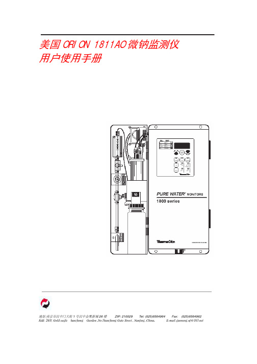
ORION 1811EL 型在线钠表技术导则

图1——钠表样水流程方框图Inlet valve——进口阀,Bypass filter——旁路过滤器,Bypass valve——旁路阀,Pressure reducing valve——压力调节阀,Flow valve——流量计入口阀,Flowmeter ——流量计,Restrictor——节流管,Calibration diverter valve——标定切换阀,Temperature probe——温度探头,Reference probe——参比电极,Sensing probe——钠电极,Calibration level——标定液位,Measuring level——测量液位,Reagent addition system——试剂扩散系统,Drain——排污管图2——钠表正常测量状态下的样水流程1 inlet valve——进口阀,2 bypass filter——旁路过滤器,3 pressure regulator ——压力调节阀,4 flowmeter——流量计,5 flow restrictor tubing——节流管,6 electrolyte reservoir——电解液瓶,7 reference probe——参比电极,8 sensing probe ——钠电极,9 temperature probe——温度探头,11 flow cell manifold——流动池组件,14 reagent diffusion botttle——试剂扩散瓶,18 air pump——空气泵,drain——排污管,36 flow valve——流量计入口阀,37 bypass valve——旁路阀1.3 干扰抑制:在测量低浓度钠离子时,为了消除氢离子的干扰,1811EL型钠表将样水的pH 值调节到11以上,这里的pH值调节是通过ORION公司取得专利权的扩散工艺来实现的,样水流经试剂扩散从而将样水的pH值提高到11以上.图5;仪表拆箱检查仪表外观有无损坏,并根据到货清单核对物品名称、规格、数量,发现问题立即与有关部门联系解决。
奥立龙 Orion 2111LL 微钠表操作说明书3.1

美国艾顿公司滤芯技术产品说明说明书

10
10
Refinery Overview and Application Portfolio
11
11
Refinery Flow Diagram
H2
Sour Gas
Amine Treating
Fuel Gas H2S
Claus Reactor
Sulfur
Gas
Gas Processing
Merox Treater
This is a photographic template – your photograph should fit precisely within this rectangle.
Filtration Technology for Oil & Gas
EATON FILTRATION (JAPAN) Ltd. Sales Manager. Shuji Yamaguchi.
world
4
4
Eaton’s growth through acquisitions
Ronningen-Petter (Sep. 2006)
• Application focused engineering in a range of industrial markets
• Range of unique solid-liquid separation and self-cleaning products
9
Markets & Industries Served
Marine
• Gearboxes • Shipbuilding Industry • Tankers
Refrigeration
Machines
美国Eaton公司产品说明书:Eaton Moeller系列xPole - mRB4 6 RCBO

Eaton 120654Eaton Moeller series xPole - mRB4/6 RCBO - residual-current circuit breaker with overcurrent protection. RCD/MCB, 16A, 100mA, B-LS-Char, 3N pole, FI-Char: AGeneral specificationsEaton Moeller series xPole - mRB4/6 RCBO - residual-current circuit breaker with overcurrent protection120654401508118484280 mm 75.5 mm 70 mm 0.446 kg CE Marked RoHS conformCE mRB6-16/3N/B/01-AProduct NameCatalog Number EANProduct Length/Depth Product Height Product Width Product Weight Compliances Certifications Model CodeSwitchgear for residential and commercial applicationsmRB6Combined RCD/MCB devicesSwitchgear for industrial and advanced commercial applications Three-pole + N44BB16 A6 - 25 Ampere0.1 AType A, pulse-current sensitiveRCBO AC400 V230 V / 400 V400 V500 V4 kV30, 100, 300 MilliAmpere Partly surge-proof, 250 A 50 HzA6 kA6 kA6 kA0.5 x I∆n6 kA6 kA6 kAApplicationProduct rangeBasic functionProduct applicationNumber of polesNumber of poles (protected) Number of poles (total) Tripping characteristic Release characteristicRated currentRated current of product range Fault current rating Sensitivity typeType Voltage typeVoltage ratingVoltage rating at ACRated operational voltage (Ue) - maxRated insulation voltage (Ui)Rated impulse withstand voltage (Uimp)Rated fault currents of product rangeImpulse withstand currentFrequency ratingLeakage current typeRated switching capacityRated switching capacity (IEC/EN 60947-2)Rated switching capacity (IEC/EN 61009)Rated non-tripping currentRated short-circuit breaking capacity (EN 60947-2) Rated short-circuit breaking capacity (EN 61009) Rated short-circuit breaking capacity (EN 61009-1) Rated short-circuit breaking capacity (IEC 60947-2)0 kA 0.25 kAUndelayed Non-delayed 100 Ampere gL 3III245 mm480 mm70 mmTri-stable slide catch - enables removal from existing busbar combinationIP20IP40Twin-purpose1 - 25 Square MillimeterBusbar tag shroud to VBG41 mm²25 mm²1 mm²25 mm²2 mmIEC 68-2: 25 °C - 55 °C at 90 % - 95 % humiditySurge current capacityDisconnection characteristic TrippingBack-up fuseSelectivity class Overvoltage category Pollution degree FrameWidth in number of modular spacingsDevice heightBuilt-in depthMounting styleDegree of protectionDegree of protection (built in)Terminals (top and bottom)Solid terminal capacitiesTerminal protectionConnectable conductor cross section (solid-core) - min Connectable conductor cross section (solid-core) - max Connectable conductor cross section (multi-wired) - min Connectable conductor cross section (multi-wired) - max Material thicknessClimatic proofing16 A0 W 11.6 W 0 W0 W-25 °C 40 °C Meets the product standard's requirements.Meets the product standard's requirements.Meets the product standard's requirements.Meets the product standard's requirements.Meets the product standard's requirements.Does not apply, since the entire switchgear needs to be evaluated.Does not apply, since the entire switchgear needs to be evaluated.Meets the product standard's requirements.Does not apply, since the entire switchgear needs to be evaluated.Meets the product standard's requirements.Does not apply, since the entire switchgear needs to be evaluated.Does not apply, since the entire switchgear needs to be evaluated.Is the panel builder's responsibility.Is the panel builder's responsibility.Is the panel builder's responsibility.Rated operational current for specified heat dissipation (In) Heat dissipation per pole, current-dependentEquipment heat dissipation, current-dependentStatic heat dissipation, non-current-dependentHeat dissipation capacityAmbient operating temperature - minAmbient operating temperature - max 10.2.2 Corrosion resistance10.2.3.1 Verification of thermal stability of enclosures10.2.3.2 Verification of resistance of insulating materials to normal heat10.2.3.3 Resist. of insul. mat. to abnormal heat/fire by internal elect. effects10.2.4 Resistance to ultra-violet (UV) radiation10.2.5 Lifting10.2.6 Mechanical impact10.2.7 Inscriptions10.3 Degree of protection of assemblies10.4 Clearances and creepage distances10.5 Protection against electric shock10.6 Incorporation of switching devices and components10.7 Internal electrical circuits and connections10.8 Connections for external conductors10.9.2 Power-frequency electric strengthIs the panel builder's responsibility.Is the panel builder's responsibility.The panel builder is responsible for the temperature rise calculation. Eaton will provide heat dissipation data for the devices.Is the panel builder's responsibility. The specifications for the switchgear must be observed.Is the panel builder's responsibility. The specifications for the switchgear must be observed.The device meets the requirements, provided the information in the instruction leaflet (IL) is observed.3Concurrently switching N-neutralIEC/EN 61009eaton-xpole-mrb4-rcbo-catalog-ca019058en-en-us.pdfeaton-xpole-mrb6-rcbo-catalog-ca019057en-en-us.pdfDA-DC-03_mRB-3N03_mRB-3p_20041603_mRB-3N_281118eaton-mcb-xpole-mrb4-6-characteristic-curve.epseaton-xeffect-frbm6/m-characteristic-curve-002.jpgDimensions xPole mRB4/mRB6 3Neaton-xeffect-frbm6/m-dimensions-004.jpgeaton-mcb-xpole-mrb4-6-dimensions.eps3D Drawing xPole mRB4/mRB6 3Neaton-xpole-combined-mcb-rcd-device-rcbo-packaging-manual-multilingual.pdfIL019140ZUDA-CS-faz_3pn_4pDA-CD-faz_3pn_4pCharacteristics xPole mRB4/mRB6 3Neaton-mcb-xpole-mrb4-6-wiring-diagram.epsContact Sequence xPole mRB4/mRB6 3N10.9.3 Impulse withstand voltage10.9.4 Testing of enclosures made of insulating material 10.10 Temperature rise10.11 Short-circuit rating10.12 Electromagnetic compatibility10.13 Mechanical function Current limiting class FeaturesStandards Catalogues Certification reports Characteristic curve DrawingsInstallation instructions mCAD modelTime/current curves Wiring diagramsEaton Corporation plc Eaton House30 Pembroke Road Dublin 4, Ireland © 2023 Eaton. All rights reserved. Eaton is a registered trademark.All other trademarks areproperty of their respectiveowners./socialmediaeaton-xeffect-frbm6/m-wiring-diagram-002.jpg。
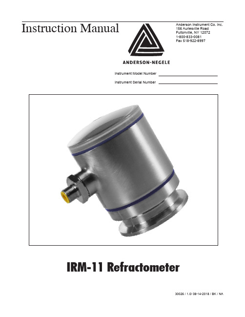
安德森仪器公司IR-11 折射计 使用说明书
These safety instructions have to be strictly observed in order:
• To not endanger the safety of persons and environment
• To avoid any damages to the measuring instrument
Electrical connection
Cable gland M16 x 1.5
Cable connection
M12 connector
Supply voltage
5…24 V DC max. 150 mA
Protection class
IP69K
Weight
480 g (1 lbs)
PAGE 5
Temperature ranges
Ambient
-10…60 °C (14...140 °F)
Process
20...100 C (-4...212 F) compensated range
CIP/SIP
Up to 140 °C (284 °F) max. 60 min
Process pressure
• To prevent any faulty product as a result of use
The electric connection may only be carried out by qualified persons who have the necessary electrical knowledge and have been authorized by the owner to do so. The wiring of the voltage supply and the output has to be carried out professionally in consideration of current electrical design and regulation. Also refer to chapter 3 “Installation”/”Electrical” for more information.
ORION1811AO
Es = E0 + S log (Cs/Ciso) E1 = E0 + S log [(Cs + dC1)/Ciso] E2 = E0 + S log [(Cs+ dC1+ dC2)/Ciso]
第 4 页 共 33 页
南京国能环保科技发展有限公司
除水温波动造成的误差,1811 型钠表微处理机不断按 ATC 温度探头所提供的数
据修正温度补偿值。
从能斯特方程可以知道,在 25℃时钠离子选择电极对十倍离子浓度变化的
理论响应值为 59.16MV,这被称为电极斜率(S)。然而大多数电极并不表现为
理论斜率。因此,需标定仪表以确定其真实斜率值。在使用中,两个标准溶液就
扩散法可以避免加入液体试剂及气体带来的问题。例如,加入液体试剂会稀 释及污染样水,而压缩气体会污染流通池。
通过压力调节阀和节流管的共同作用可控制进入流通池的样水的样水的流 量。调节压力调节阀,得到一个 25ml/min 的标准流量,在正常测量期间,将流 通池的切换阀拉出以保证流通池的样水的体积为 20ml,因此,系统的快速响应 时间是由样水流速和样水体积共同决定的。
1811AO 说明书
图3:系统图
此处:E=测量的电极电位 E0=电位,当 C=Ciso 时,MVR=理气体常数 T=样水绝对温度,K
N=离子价态(钠离子的价态为+1)
F=法拉利常数
C=钠离子有效浓度(活度)
Ciso=当电位 E 与温度无关时(等电位点)的钠离子浓度(活度)
能斯特方程表明,所测量的电位随着温度和相关浓度的变化而改变。为了消
维修服务
配合的注意事项
- 1、下载文档前请自行甄别文档内容的完整性,平台不提供额外的编辑、内容补充、找答案等附加服务。
- 2、"仅部分预览"的文档,不可在线预览部分如存在完整性等问题,可反馈申请退款(可完整预览的文档不适用该条件!)。
- 3、如文档侵犯您的权益,请联系客服反馈,我们会尽快为您处理(人工客服工作时间:9:00-18:30)。
美国奥立龙Orion1811AO钠表,1811EL钠表,2111XP钠表,2111LL钠表,2230硅表,2030硅表配件一览表:
美国ORION公司1811AO钠表配件
序号配件名称单位订货号备注
1钠电极支100045
2参比电极支100056
3参比电极内充液套181073
4“O”型圈套181121
5扩散瓶组件套212861-A01
6压力调节器套181123
7流量调节器套503922-A01
8限流组件套181125
9流量池组件套181126
10温度探头套181127
11扩散管套181160
12标准液套181140
13校验箱套181149
14进水过滤装置套181120
15高浓度标准套181141
1630天用钠试剂套181130
17空气泵套181173
18易耗品(一年用)套181150
19吸嘴套204846-001
20电源板块802062-A01
21带驱动板的键盘块503951-A01
22截止阀组件套210582-A01
23电极电缆根703275-A01
美国ORION公司1811EL钠表配件
序号配件名称单位订货号备注
1钠电极支100048
2参比电极支100058
3参比电极内充液套150072
4“O”型圈套181121
5扩散瓶组件套212861-A01
6压力调节器套181123
7流量调节器套503922-A01
8限流组件套181125
9流量池组件181126套207808-001
10温度探头套181127
11过滤滤芯套181170
12过滤滤芯密封件套181171
13空气泵组件套181173
14扩散管套150060
15扩散管套150063
16标准液套181140
17校验箱套181148
18一年用试剂(化学危险品)套151111
19一年用消耗包套181153
20吸嘴盒207525-001
21电源板块802062-A01
22带驱动板的键盘块503951-A01
23截止阀组件套210582-A01
24电极电缆根703275-A01
25PMA主机板电源电缆根703278-A01
26电源开关个204743-A01
27钠表电池块204353-001
28钠表移液枪支207524-001
美国ORION公司2111LL钠表配件
序号配件名称单位订货号备注1钠电极支210048
2参比电极支210058
3电极电缆根21003M
4参比电极内充液套150072
5温度探头套2100TP
6温度电极电缆根2001XT
7空气泵组件套2111PA
8扩散管套211194
9阀组件(左侧)套2111LVA
10阀组件(右侧)套2111RVA
11关闭阀套2111SV
12转向阀只2111DV
13检查阀只2111VC
14旁路/针阀组件只2100BV
15压力调节阀只2100RG
16排水接头和夹子组件套2100DA
17空气过滤器组件套2100AF
18限流管组件只2100RT
19检查阀只2111VC
20流量计组件套2111FM
21O型圈套件套2111LLOK
22测量池组件套2111FC
23测量池盖套2111CA
24标准液套181140
25校验箱套181148
26试剂(两个月)套211190
27一年用试剂(化学危险品)套211191
28一年用消耗包套211192
29试剂瓶适配器只2100DRBA
30主板块2111LLEP
31维护包套2111MK
美国ORION公司2111XP钠表配件
序号配件名称单位订货号备注1测量电极支210045
2参比电极支210056
3内充液套181073
4钠试剂瓶181130
5扩散管根150060
6低钠标液套181140
7高钠标液套181141
8钠试剂瓶211190
9扩散管根211194
10电极电缆(2根/套)套21003M
11自动温度补偿(ATC)支2100TP
12电极活化液瓶181113
13扩散管根181160
14年度消耗包套211150XP
18适配器只2100DRBA
19适配器只2100ARBA
20O型圈垫圈套2100OK
21保险丝只2100FK230
22钠表电源组件块2100PS
23钠表主板块2111XPEP
24动态校正器台15DC20
美国ORION公司2030硅表配件
序号配件名称单位订货号备注1空气阀230807-001
2数字转换板230808-001
3显示模块230809-001
4光纤230810-001
5流量传感器230811-001
6浸没探头230812-001
7键盘230813-001
8主板230814-001
9多通道板230815-001
10光学滤波器230816-001
11光学滤波器230817-001
12蠕动泵组件230818-001
13柱塞泵组件230819-001
14电源230820-001
15反应池(流通池)230821-001
16反应池套件230822-001
17电缆230823-001
18单流路模块230824-001
19双流路模块230825-001
206通道模块230826-001
21虹吸管230827-001
22电磁阀230828-001
23搅拌组件230829-001
24泵轴组件231480-001
25柱塞泵头231481-001
26单向阀203278-001
27搅拌子2030SB
28维护套件(含泵管、搅拌子)2030MK
29硅表灯泡2030LA
30硅表试剂2030RG
31硅表试剂2030RE
美国ORION公司2230硅表配件
序号配件名称单位订货号备注
1硅表试剂2230RE
2硅表试剂套件2230RG
3硅表标液223020
4硅表标液223010
5硅表维护套件2230MK
6硅表泵管2230MLFR
7样品池2230SAC
8样品池2230SCFS
9试剂管夹紧阀267697-001
10主体管子套件2230TK
11试剂桶2230BK
12测量池排污弯头2230PVDF
13电源组件2230PS
142230泵体2230MTR
15蠕动泵压盖2230PA
16蠕动泵泵头2230PH1
17蠕动泵泵头2230PH2
美国奥立龙Orion1811AO钠表,1811EL钠表,2111XP钠表,2111LL钠表,2230硅表,2030硅表配件。