口感功率计算器(Kanthal A1)
咖啡机售价对比
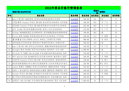
2012年商品价格行情调查表
调查日期:2012年9月份 序号 39 40 41 42 43 44 45 46 47 48 49 50 51 52 53 54 55 56 57 商品名称 Fxunshi/华迅仕 MD-800 多功能电动自动磨豆机研磨机磨咖啡豆 Delonghi/德龙 EC410 泵压意式特浓咖啡机 全国联保两年 包邮 ACA/北美电器 AC-M125A 咖啡机家用全自动咖啡机商用魔豆特价包邮 小家电 全自动咖啡机咖啡壶 泡茶机Fxunshi/华迅仕 MD-211特价 Delonghi/德龙 EC155 泵压意式特浓咖啡机 全国联保两年 包邮 Petrus/柏翠 PE3800 家用意式高压蒸汽半自动咖啡机 可打奶泡 【狂暑季】Fxunshi/华迅仕 MD-2001 蒸汽压力咖啡机|壶|秒杀 Nathome NKF6002北欧欧慕美式滴漏式咖啡壶茶饮机 正品包邮送礼品 Electrolux/伊莱克斯 ECM-4100全自动磨豆 家用蒸汽 滴漏式咖啡机 送奶泡杯 Fxunshi/华迅仕 MD-2001 家用意式咖啡机 半自动打奶泡 艾薇 JS-65C 家用美式半自动咖啡机 滴漏式煮咖啡壶 包邮送咖啡粉 特价大码女式修身pu皮衣 休闲翻领朋克小外套 欧美风机车短款夹克 【品牌特卖】veilond 2012秋装新款女士机车短款皮衣上衣修身 Midea/美的 D004B 家用全自动咖啡机 煮蒸汽咖啡壶泡茶包邮 Philips/飞利浦 HD8745 Saeco/喜客 全自动意式咖啡机 联保2年 法慕小城 老式 复古打字机 作旧摆设/居家咖啡馆店铺复古装修必备 天猫促销 自动保温 咖啡机Fxunshi/华迅仕 MD-208咖啡壶小家电 #手机淘宝#比伦奴秋装新款韩版机车短款女士皮衣皮夹克女2024特价 可用咖啡胶囊 AAA 3A-C203M3 半自动泵式蒸汽压力意式咖啡机 包邮
美国NutriBullet公司的NutriBullet RX电子椰子汁机说明书

·启动保护当加大油门后两秒内未能正常启动马达,电调将关闭动力输出,油门摇杆需再 次置于最低点后才可以重新启动。
(出现这种情况的原因可能有:电调和马达 连线接触不良或有个别输出线断开、螺旋桨被其他物体阻挡等)。
·堵转保护当电调检测到电机发生堵转时,电调会彻底关闭输出并不再尝试重启电机,此 时需将油门摇杆置于最低后重新推动油门摇杆,方可清除错误并重启电调恢复动力输出。
·电流保护当瞬间电流异常达到接近300A时,电调立即关断输出,重新上电后可恢复正常。
·油门信号丢失保护当电调检测到油门遥控信号丢失0.25秒以上即立即关闭输出,以免因螺旋桨继 续高速转动而造成更大的损失。
信号恢复后,电调也随即恢复相应的功率输出。
保护功能1、调整LED灯色使用工具将紧固灯罩的M3×8螺钉取出,按照以下对应的灯色设置开关,设置 成功后原方式组装将灯罩紧固。
2、更换桨叶· 用工具依次将两个桨叶紧固螺钉外六角M6x22取出,换上完好桨叶,若需要 更换桨夹则继续使用工具将桨夹紧固螺钉M3x10取出更换整套桨夹加桨叶。
· 安装桨夹桨叶时先将底盖安装在电机上面,再依次安装桨片、螺旋桨垫片、上 盖(桨夹)以及最后的螺钉紧固;注意安装桨叶螺钉夹紧后桨叶可自由旋转并 确保桨夹与电机紧固螺钉拧紧同时使用螺丝胶。
飞机坠毁后造成的系统维护请及时联系好盈售后客服,在不影响性能的前提下,并确保跟客服联系后可自行使用好盈动力系统套装配件进行更换,禁止用户自行配置配件(如螺钉,桨夹,桨叶)更换使用;若造成严重损害请联系售后及时返修。
警示音说明日常使用售后维护动力参数。
Sennheiser G3 无线电话系列产品说明说明书

ew 100 Setsew 112 G3 Presentation Setew 122 G3 Presentation Set ew 152 G3 Headsetew 172 G3 Instrument Setew 135/145/165 G3 Vocal SetsThe ew 122 G3 is a wireless microphone set. The ew 122 G3 consists of thesame components as ew 112 G3 but with ME 4 clip-on cardioid microphone.The compact clip-on microphone rejects noises coming from the side which means less risk of feedback.The ew 152 G3 is a wireless microphone set. The ew 152 G3 consists of the same components as ew 112 G3 but with ME 3 headworn cardioid microphone.The included condenser headworn microphone is easy to wear, has great pop protection and produces powerful sound.FEATURESSturdy metal housing (transmitterand receiver)42 MHz bandwidth: 1,680 tunable UHF frequencies for interference-free reception Enhanced frequency bank system with up to 12 compatible frequenciesHigh-quality true diversity reception Automatic frequency scan feature searches for available frequencies Pilot tone squelch for eliminating RF interference when transmitter is turned offEnhanced AF frequency rangeIncreased range for audio sensitivityWireless synchronization of transmitters via infrared interfaceIlluminated graphic display (transmitter and receiver)Auto-Lock function avoids accidental changing of settingsHDX compander for crystal-clear sound Transmitter feature battery indicatation in 4 steps, also shown on receiver display Programmable Mute function Integrated Equalizer and Sound c heck mode Contacts for recharging BA 2015 accupack directly in the transmitterWide range of accessories adapts the system to any requirementThe ew 112 G3 is a wireless microphone set, consisting of a True Diversityreceiver, a bodypack transmitter with ME 2 clip-on omni-directional microphone plus accessories. It is versatile for every style of presentations.A wireless link from receiver to the transmitter allows synchronization of frequencies for easy setup. Backlit graphic displays make them easy to read under all lighting conditions.The ew 135 G3 is a wireless microphone set, consisting of a True Diversityreceiver, a handheld transmitter with e 835 microphone head plus accessories. It is versatile for every style of music and presentations. A wireless link from receiver to the transmitter allows synchronization of frequencies for easy setup. Backlit graphic displays make them easy to read under all lighting conditions.The ew 145 G3 consists of the same components as ew 135 G3but with an e 845 microphone head.The ew 165 G3 consists of the same components as ew 135 G3but with an e 865 microphone head.FEATURESew 135 G3/ew 145 G3/ ew 165 G3 Vocal SetsSee above mentioned list of features plus Handheld transmitter with easy-exchangeable microphone heads from evolution seriesThe ew 172 G3 is a wireless instrument set, consisting of a True Diversityreceiver, a bodypack transmitter with CI 1 jack cable plus accessories. It is versatile for picking up instruments.The system features a virtual cable emulator to get sound response just like a cable, a built-in guitar tuner and an EQ. The frequency respon-se starts at 25 Hz for natural bass reproduction.ARCHITECT’S SPECIFICATIONSew 112 G3 Presentation SetComplete plug & play wireless microphone set with clip-on microphone (permanent polarized, omni-directional) for multi-purpose application. The devices shall have metal housings for rugged use. 42 MHz bandwidth with 1,680 tunable frequencies. 20 banks with up to 12 compatible frequencies, 1 bank for individual selectable frequencies. Scan function and wireless synchronization to the transmitter for easy setup. HDX compander delivers high-quality sound performance. The transmitter shall have a sensitivity range of 48 dB. The receiver offers a maximum output level of +18 dBu (+6 dB gain). True Diversity and pilot tone squelch for interference-free reception.The transmitter shall have a programmable Mute switch (RF on/off, AF on/off, disabled)Charging contacts on transmitter for recharging BA 2015 accu pack directly in the transmitter shall be available. 3-step battery + Low-Battery indication on transmitter and receiver shall give reliable information on operation time. Menu operation, auto-lock function and illuminated graphic displays on transmitter and receiver for user-friendly operation.A RF Mute function on transmitter and receiver allows offline settings. An equalizer and soundcheck mode is integrated in the receiver.A wide range of clip-on and headworn microphones and accessories shall be available for the system. The wireless microphone system shall feature a true-diversity receiver with 42 MHz of available tuning bandwidth with a total of 1,680 frequencies accessible in 25 kHz steps. The wireless microphone receiver must feature one balanced XLR output with a max. output of +18 dBu, and one unbalanced ¼” output with a max. output of +12 dBu. The wireless microphone receiver must feature two BNC antenna inputs, one for each receiver module in the true diversity system.The wireless microphone receiver must feature an automatic frequency scanning function that utilizes twenty (20) banks of pre-coor-dinated frequencies that are free of intermodulation interference. The wireless microphone receiver must also feature a user bank in order to store user defined frequencies. The wireless microphone transmitter must operate on two 1.5 V AA battery cells. The wireless microphone transmitter must have access to 1,680 frequencies tuned in 25 kHz steps across a defined 42 MHz bandwidth. The wireless microphone transmitter must feature a backlit display that displays frequency information, AF level, battery level. The wireless micro-phone transmitter must transmit a pilot-tone squelch. The wireless microphone transmitter must have a specified RF output power of 30 mW. The wireless microphone receiver must accept 12 V DC power via BNC antenna inputs.ew 122 G3 Presentation SetComplete plug & play wireless microphone set with clip-on microphone (condenser, cardioid) from Sennheiser evolution series for multi-purpose application. Further discription see paragraph ew 112 G3.ew 152 G3 Head SetComplete plug & play wireless microphone set with headworn microphone (permanent polarized, cardioid) for hands-free application. Further discription see paragraph ew 112 G3.ew 172 G3 Head SetComplete plug & play wireless instrument set from Sennheiser evolution series for multi-purpose application.Further discription see paragraph ew 112 G3.ew 135 G3 Vocal SetComplete plug & play wireless microphone set with easy-exchangeable e 835 microphone head (dynamic, cardioid) from Sennheiser evolution series for multi-purpose application. Further discription see paragraph ew 112 G3.ew 145 G3 Vocal SetComplete plug & play wireless microphone set with easy-exchangeable e 845 microphone head (dynamic, super-cardioid) from Sennheiser evolution series for multi-purpose application. Further discription see paragraph ew 112 G3.ew 165 G3 Vocal SetComplete plug & play wireless microphone set with easy-exchangeable e 865 microphone head (electret-condenser, super-cardioid) from Sennheiser evolution series for multi-purpose application. Further discription see paragraph ew 112 G3.SySTEMRF frequency range ................................................ 516…865 MHz1,785....1,800 MHzTransmission/receiving frequencies ................... 512.....1,865 MHz: 1,6801,785....1,800 MHz: 1,500Presets (12)Switching bandwidth ............................................. 512.....1,865 MHz: 42 MHz1,785....1,800 MHz: 15 MHzCompander ...............................................................HDXFrequency response ...............................................25…18,000 HzSignal-to-noise ratio ..............................................> 110 dB(A)THD, total harmonic distortion ............................< 0,9 %RECEIVERSTrue diversityAntenna connector .................................................2 x BNC, 50 OAudio output level (balanced) .............................XLR: +18 dBu maxAudio output level (unbalanced) ........................Jack: +12 dBu maxDimensions ...............................................................202 x 212 x 43 mmWeight .......................................................................~ 900gTRANSMITTERRF output power .....................................................typ. 30 mW battery AA (Mignon)Power supply............................................................2 x AA batteriesOperating time ........................................................typ. 8hInput voltage range mic ........................................1.8 V effInput voltage range line ........................................3 V effDimensions ...............................................................82 x 64 x 24 mmWeight .......................................................................~ 160gContinued on page 5Microphones (SK 100)ME 2ME 3-ew ME 4Microphone type .............................condenser condenser condenserSensitivity .........................................20 mV/Pa 1.6 mV/Pa40 mV/PaPick-up pattern ................................omni-directional cardioid cardioidMax. SPL ............................................130 dB SPL150 dB SPL120 dB SPL Microphone heads (SKM 100)MMD 835-1MMD 845-1MMK 865-1Radio microphone type .................dynamic dynamic condenserSensitivity ......................................... 2.1 mV/Pa 1.6 mV/Pa 1.6 mV/PaPick-up pattern ................................cardioid super-cardioid cardioid/super-cardioid,switchableMax. SPL ............................................154 dB SPL154 dB SPL152 dB SPL Frequency response .......................80.....18,000 Hz80.....18,000 Hz80.....18,000 HzDELIVERY INCLUDES for ew 112 / ew 122 / ew 152 / ew 172 G31 EM 100 G3 rack-mount receiver1 SK 100 G3 bodypack transmitter1 ME2 clip-on microphone (omni-directional) (ew 112) or1 ME 4 clip-on microphone (cardioide) (ew 122) or1 ME 3-ew headset microphone (cardioid) (ew 152) or1 CI instrument cable (ew 172)1 NT2 power supply unit2 Antennas2 Stacking elements2 AA batteries1 Instruction ManualDELIVERY INCLUDES for ew 135 / ew 145 / ew 165 G31 S KM 100-835 G3 handheld transmitterwith cardioid dynamic head or1 S KM 100-845 G3 handheld transmitterwith super-cardioid dynamic head or1 S KM 100-865 G3 handheld transmitterwith super-cardioid condenser head1 EM 100 G3 rack receiver1 MZQ 1 microphone clip1 NT2 power supply unit2 Antennas2 Stacking elements2 AA batteries1 Instruction ManualPOLAR PATTERN0510152025dB30°30°60°60°90°90°120°150°120°150°0°180°125 Hz 250 Hz 500 Hz 1000 Hz2000 Hz 4000 Hz 8000 Hz 16000 HzME 3-ewME 4-ewMMD 835-1MME 865-1MMD 845-10510152025dB30°30°60°60°90°90°120°150°120°150°0°180°125 Hz 250 Hz 500 Hz 1000 Hz2000 Hz 4000 Hz 8000 Hz 16000 Hz0510152025dB30°30°60°60°90°90°120°150°120°150°0°180°125 Hz 250 Hz 500 Hz 1000 Hz2000 Hz 4000 Hz 8000 Hz 16000 Hz0510152025dB30°30°60°60°90°90°120°150°120°150°0°180°125 Hz 250 Hz 500 Hz 1000 Hz2000 Hz 4000 Hz 8000 Hz 16000 Hz0510152025dB30°30°60°60°90°90°120°150°120°150°0°180°125 Hz 250 Hz 500 Hz 1000 Hz2000 Hz 4000 Hz 8000 Hz 16000 Hzew 112 G3 Presentation Set Cat. No. ew 112 G3-A-EU 516...558 MHz 503100 ew 112 G3-A-US 516...558 MHz 503169 ew 112 G3-A-UK 516...558 MHz 503170 ew 112 G3-G-EU 566...608 MHz 503171 ew 112 G3-G-US 566...608 MHz 503172 ew 112 G3-G-UK 566...608 MHz 503173 ew 112 G3-B-EU 626...668 MHz 503174 ew 112 G3-B-US 626...668 MHz 503175 ew 112 G3-B-UK 626...668 MHz 503176 ew 112 G3-C-EU 734...776 MHz 503177 ew 112 G3-C-US 734...776 MHz 503178 ew 112 G3-C-UK 734...776 MHz 503179 ew 112 G3-D-EU 780...822 MHz 503180 ew 112 G3-D-EU-X 780...822 MHz 503181 ew 112 G3-D-UK 780...822 MHz 503182 ew 112 G3-E-EU 823...865 MHz 503183 ew 112 G3-E-EU-X 823...865 MHz 503184 ew 112 G3-E-UK 823...865 MHz 503185 ew 112 G3-GB 606…648 MHz 504638 ew 112 G3-1G8 1,785…1,800 MHz504900 ew 122 G3 Presentation Set Cat. No. ew 122 G3-A-EU 516...558 MHz 503101 ew 122 G3-A-US 516...558 MHz 503187 ew 122 G3-A-UK 516...558 MHz 503188 ew 122 G3-G-EU 566...608 MHz 503189 ew 122 G3-G-US 566...608 MHz 503190 ew 122 G3-G-UK 566...608 MHz 503191 ew 122 G3-B-EU 626...668 MHz 503192 ew 122 G3-B-US 626...668 MHz 503193 ew 122 G3-B-UK 626...668 MHz 503194 ew 122 G3-C-EU 734...776 MHz 503195 ew 122 G3-C-US 734...776 MHz 503196 ew 122 G3-C-UK 734...776 MHz 503197 ew 122 G3-D-EU 780...822 MHz 503198 ew 122 G3-D-EU-X 780...822 MHz 503199 ew 122 G3-D-UK 780...822 MHz 503200 ew 122 G3-E-EU 823...865 MHz 503201 ew 122 G3-E-EU-X 823...865 MHz 503202 ew 122 G3-E-UK 823...865 MHz 503203 ew 122 G3-GB 606…648 MHz 504639 ew 122 G3-1G8 1,785…1,800 MHz504901ew 152 G3 Presentation Set Cat. No.ew 152 G3-A-EU 516...558 MHz 503102ew 152 G3-A-US 516...558 MHz 503205ew 152 G3-A-UK 516...558 MHz 503206ew 152 G3-G-EU 566...608 MHz 503207ew 152 G3-G-US 566...608 MHz 503208ew 152 G3-G-UK 566...608 MHz 503209ew 152 G3-B-EU 626...668 MHz 503210ew 152 G3-B-US 626...668 MHz 503211ew 152 G3-B-UK 626...668 MHz 503212ew 152 G3-C-EU 734...776 MHz 503213ew 152 G3-C-US 734...776 MHz 503214ew 152 G3-C-UK 734...776 MHz 503215ew 152 G3-D-EU 780...822 MHz 503216ew 152 G3-D-EU-X 780...822 MHz 503217ew 152 G3-D-UK 780...822 MHz 503218ew 152 G3-E-EU 823...865 MHz 503219ew 152 G3-E-EU-X 823...865 MHz 503220ew 152 G3-E-UK 823...865 MHz 503221ew 152 G3-GB 606…648 MHz 504640ew 152 G3-1G8 1,785…1,800 MHz504902ew 172 G3 Instrument Set Cat. No.ew 172 G3-A-EU 516...558 MHz 503103ew 172 G3-A-US 516...558 MHz 503223ew 172 G3-G-EU 566...608 MHz 503224ew 172 G3-G-US 566...608 MHz 503225ew 172 G3-B-EU 626...668 MHz 503226ew 172 G3-B-US 626...668 MHz 503227ew 172 G3-C-EU 734...776 MHz 503228ew 172 G3-C-US 734...776 MHz 503229ew 172 G3-D-EU 780...822 MHz 503230ew 152 G3-D-EU-X 780...822 MHz 503231ew 172 G3-D-UK 780...822 MHz 503332ew 172 G3-E-EU 823...865 MHz 503233ew 172 G3-E-EU-X 823...865 MHz 503234ew 172 G3-E-UK 823...865 MHz 503235ew 152 G3-GB 606…648 MHz 504641ew 152 G3-1G8 1,785…1,800 MHz504903Continued on page 10ew 135 G3 Vocal Set Cat. No. ew 135 G3-A-EU 516...558 MHz 503104 ew 135 G3-A-US 516...558 MHz 503237 ew 135 G3-A-UK 516...558 MHz 503238 ew 135 G3-G-EU 566...608 MHz 503239 ew 135 G3-G-US 566...608 MHz 503240 ew 135 G3-G-UK 566...608 MHz 503241 ew 135 G3-B-EU 626...668 MHz 503242 ew 135 G3-B-US 626...668 MHz 503243 ew 135 G3-B-UK 626...668 MHz 503244 ew 135 G3-C-EU 734...776 MHz 503245 ew 135 G3-C-US 734...776 MHz 503246 ew 135 G3-C-UK 734...776 MHz 503247 ew 135 G3-D-EU 780...822 MHz 503248 ew 135 G3-D-EU-X 780...822 MHz 503249 ew 135 G3-D-UK 780...822 MHz 503250 ew 135 G3-E-EU 823...865 MHz 503251 ew 135 G3-E-EU-X 823...865 MHz 503252 ew 135 G3-E-UK 823...865 MHz 503253 ew 135 G3-GB 606…648 MHz 504642 ew 135 G3-1G8 1,785…1,800 MHz504904 ew 145 G3 Vocal Set Cat. No. ew 145 G3-A-EU 516...558 MHz 503105 ew 145 G3-A-US 516...558 MHz 503255 ew 145 G3-G-EU 566...608 MHz 503256 ew 145 G3-G-US 566...608 MHz 503257 ew 145 G3-B-EU 626...668 MHz 503258 ew 145 G3-B-US 626...668 MHz 503259 ew 145 G3-C-EU 734...776 MHz 503260 ew 145 G3-C-US 734...776 MHz 503261 ew 145 G3-D-EU 780...822 MHz 503262 ew 145 G3-D-EU-X 780...822 MHz 503263 ew 145 G3-D-UK 780...822 MHz 503264 ew 145 G3-E-EU 823...865 MHz 503265 ew 145 G3-E-EU-X 823...865 MHz 503266 ew 145 G3-E-UK 823...865 MHz 503267 ew 145 G3-GB 606…648 MHz 504643 ew 145 G3-1G8 1,785…1,800 MHz504905ew 165 G3 Vocal Set Cat. No. ew 165 G3-A-EU 516...558 MHz 503106 ew 165 G3-A-US 516...558 MHz 503269 ew 165 G3-G-EU 566...608 MHz 503270 ew 165 G3-G-US 566...608 MHz 503271 ew 165 G3-B-EU 626...668 MHz 503272 ew 165 G3-B-US 626...668 MHz 503273 ew 165 G3-C-EU 734...776 MHz 503274 ew 165 G3-C-US 734...776 MHz 503275 ew 165 G3-D-EU 780...822 MHz 503276 ew 165 G3-D-EU-X 780...822 MHz 503277 ew 165 G3-D-UK 780...822 MHz 503278 ew 165 G3-E-EU 823...865 MHz 503279 ew 165 G3-E-EU-X 823...865 MHz 503280 ew 165 G3-E-UK 823...865 MHz 503281 ew 165 G3-GB 606…648 MHz 504644 ew 165 G3-1G8 1,785…1,800 MHz504906RECOMMENDED ACCESSORIESCat. No. Earworn microphones, 3.5 mm jack plugomni:black Ear Set 1-ew504232 beige Ear Set 1-ew-3 504233cardioid:black Ear Set 4-ew504236 beige Ear Set 4-ew-3504237Clip-on microphones, 3.5 mm jack plug omni:black MKE 1-ew502876 white MKE 1-ew-1502877 brown MKE 1-ew-2502878 beige MKE 1-ew-3502879 black MKE 2-ew Gold009831 beige MKE 2-ew-3 Gold 009832 black MKE 40-ew500527Headmicrophones thin connection cable, 3.5 mm jack plugomni:black HSP 2-ew009866 beige HSP 2-ew-3009872 cardioid:black HSP 4-ew009867 beige HSP 4-ew-3009873Headmicrophones thin connection cable, 3.5 mm jack plug, shorter microphone boom and smaller neckbandomni:black HSP 2-ew-M500693 beige HSP 2-ew-3-M500692 cardioid:black HSP 4-ew-M500699 beige HSP 4-ew-3-M500698Antenna Splitter for 1800 MHz – ASA 1-1G8504914 Antenna Booster for 1800 MHz – AB 3-1G8504915 Directional Antenna for 1800 MHz – AD 1800504916 19“ RackMount Kit – GA 3503167 Antenna Front Mount Kit – AM 2009912 Power supply for one L 2015NT 1-1-EU (EU version, 230 V) 503158 NT 1-1-UK (UK version, 230 V) 503874 NT 1-1-US (US version, 120 V) 503873 Power supply for up to three L 2015NT 3-1-EU (EU version, 230 V) 503159 NT 3-1-UK (UK version, 230 V) 503877 NT 3-1-US (US version, 120 V) 503876 GA 3 – Rack-mount kit 503167 AM 2 – Antenna Mount kit 009912 CC 3 – System Case 503168 L 2015 – Charging unit 009828 BA 2015 – Rechargeable battery pack 009950Cat. No. ASA 1 – Active antenna splitter 503165 A 1031 – Antenna 004645 A 2003 – Passive directional antenna 003658 AB 3 – Antenna booster 021822 ME 4 – Clip-on microphone, cardioid, black 503156 CI 1 – Instrument cable 503163 ew 135 / ew 145 / ew 165 G3 Vocal SetsMMD 835-1 – evolution microphone head 502575 MMD 845-1 – evolution microphone head 502576 MME 865-1 – evolution microphone head 502581 MZW 1 – Windshield 004839 KEN 2 – Identification rings 530195 LA 2 – Charging adapter forhandheld microphones 503162 CC 3 – System case 503168Sennheiser electronic GmbH & Co. KG Am Labor 1, 30900 Wedemark, Germany 0 4 / 1 3 S e n n h e i s e r i s a r e g i s t e r e d t r a d e m a r k o f S e n n h e i s e r e l e c t r o n i c G m b H & C o . K G . w w w . s e n n h e i s e r . c o m . C o p y r i g h t ©0 4 / 2 0 1 3 . A l l r i g h t s r e s e r v e d . E r r o r s a n d o m i s s i o n s e x c e p t e d .ew 100 SetsContact your local Service Partner:。
蒸汽+烧烤56A 果田
普通蒸汽
烧烤功能
热风对流
高温蒸汽
解冻
保温
杀菌
时钟
童锁
水位状态
工作状态
功能图标介绍:
图标
按键/旋钮名称
增加
确定/暂停
减少
功能介绍
增加时间或者温度的数值。 1.启动烹调程序; 2.暂停正在进行的烹调程序。 减少时间或者温度的数值。
开机/关机复位/取消 1.开机,2.关机,3.复位,4.取消
6
功能调节
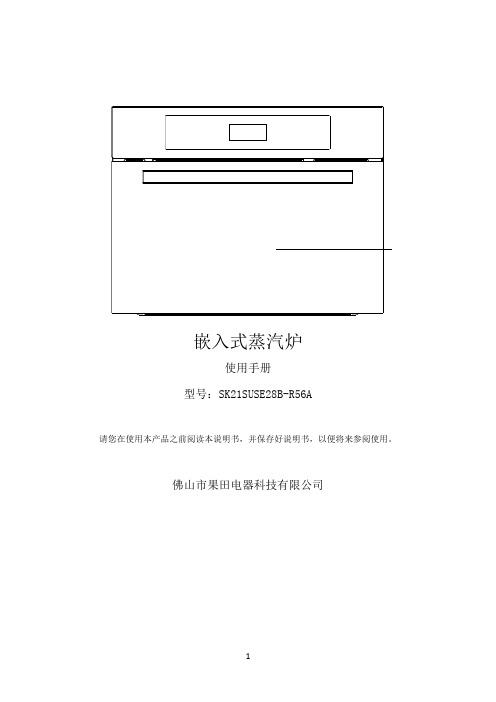
嵌入式蒸汽炉
使用手册 型号:SK21SUSE28B-R56A
请您在使用本产品之前阅读本说明书,并保存好说明书,以便将来参阅使用。
佛山市果田电器科技有限公司
1
目录
规格 安装 安全使用要点 外观结构及器皿说明 控制面板说明 操作方法
调节时钟 普通蒸汽 烧烤功能 热风对流 高温蒸汽 解冻 杀菌 保温 童锁 使用常识 清洁与保养 故障排除 随机附件
此【 式;
】键,复位到时钟模式;在时钟模式下,如果用户没有操作机器,机器自动进入省电模
பைடு நூலகம்
【
】键:
此键有两个功能,1,确定,2,暂停
当用户在功能工作的模式下需要暂停机器,直接按【
】键,暂停当前功能状态,如需要
启动,再点按此【 】键,继续当前的功能进行烹调,
【
】键:
此键有两个功能,1,炉灯,2,童锁
当用户直接点按此键,炉灯亮,如果点按此键时间超过 5 秒,进入童锁状态,显示屏上的【 】 童锁图标闪烁,在此状态下,再点按此键时间 5 秒,童锁状态取消;
杀菌
例如:对餐具杀菌:设置 20 分钟,温度 110℃; 操作步骤:
Zanolli单机烤箱产品说明书

[EN][DE][ES][FR][IT][PL][RU]***************************Singl e i e S u i t a b l e f o r Z a n o l l i Z1212Pizza ovens (old series)Item OrderDescription Model OEM 14155282000W/230V ELP2/424164322500W/230V ELP500Item OrderDescription Model OEM 14155241100W/230V ELP1/ELP501/1G 14155251100W/400V ELP501/2G24155271500W/230V ELP502/1G 24155261500W/400V ELP502/2G 1234Item OrderDescription Model OEM 1301001switch, 230V universal INTE00042301003switch, 230V INTE00103359156signal lamp LAMP00024359157signal lamp LAMP0006123123Item Order DescriptionModel OEM 1379034thermostatELP501/502, Ist generation 2345574switch3110205knob 123Item Order Description Model OEM 1375101thermostat, 370C ELP1, ELP21375132thermostat, 500C ELP500/501/5022110189knob universal 3110537symbol ring Item Order Description Model OEM 1375065safety thermostat universal TERM00052359068lamp holder 3359611lamp, 40W 132Item Order Description Model OEM1379204thermometer ELP501/502, 2nd generation 2379062sensor TCJ3379054transformer Pos.Order Description Model OEM1700085window glass ELP1/501/502S u i t a b l e f o r Z a n o l l iZ S gle d vic s123Item OrderDescription Model OEM 1401200keypad board Polis ELET01492401201main p.c.b.ELET01483379941sensor (J)TERM0020Ovens and pizza ovens12345Item OrderDescription Model OEM 1301003switch Citizen INTE00102301002switch INTE00093346361switch INTE00114359178signal lamp/green LAMP00065359180signal lamp/yellow LAMP0002123Item OrderDescription Model OEM 1379568elctronic controller Citizen TERM00122401198transformer ELET00943379941sensor (J)TERM00201231234Item OrderDescription Model OEM 1375065safety thermostat Polis, Citizen, gas TERM00052380261contactor Polis ELET00023550691safeguard clamp -ELET0058123Item OrderDescription Model OEM 14181131000W/220V (in the front)Polis T2/4RESI006824181161000W/220v (at the back)RESI005134181141300W/220V (in the front)Polis T3/6RESI006944181151300W/220V (at the back)RESI0052123Item OrderDescription Model OEM 1359666lamp holder Citizen LAMO00082359614lamp LAMP00033693380lens CRIS0023no picture Item OrderDescription Model OEM 1359664lamp holder Polis LAMP00212359665halogen lamp LAMP0037ELET022********lens CRIS0006Singl e i e S u i t a b l e f o r Z a n o l l i ZComponents (gas)1212Item OrderDescription Model OEM 1101017ignition unit Citizen ELET01352102339electrode AGHS0014Components (mechanical)12Item OrderDescription Model OEM 1693384hinge (right)Polis UPP0207UPP01392693385hinge (left)UPP0206UPP0140123Item Order Description Model OEM 1693386spring (right)Polis, Citizen SPRI00102693387spring (left)SPRI00093900456gasket GUAR0010123Item Order Description Model OEM 1693375window glassPolis T2/4, Cit-izen 9CRIS00252693376window glassPolis T3/6CRIS00283693377window glass Citizen 6CRIS00261234Pizza ovens (pass)Front screensItem Order Description Model OEM 1375002thermostat Synthesis (gas)ELET00132301020push button INTE00123359791signal lampLAMP00074346361changer switch INTE00111234Item OrderDescription Model OEM 1380015energy regulator Synthesis/E (manual)TERM00142111741knob MANI00213300189potentiometer Synthesis-gas/electri-cal (manual)ELET020********knob MANI0022Item OrderDescription Model OEM 1101984valve Citizen gasI00072102338ignition control module ELET 123Item Order Description Model OEM 1301001switch Synthesis (gas/electric)INTE00042301002switch INTE00093301003switch INTE0010S u i t a b l e f o r Z a n o l l iZ 12Item OrderDescription 1359178lamp/green Synthesis (gas/electric)LAMP00062359180lamp/yellow LAMP0002212312312312Item OrderDescription Model OEM 1401206motor card 123Item Order Description Model 1500809gear motor universal 2500650air ciculation motor 05/40MOTO00033500651air ciculation motor 08/50, 10/75MOTO0030123Item OrderDescription Model OEM 1601215fan wheel, Ø250mm 05/40VENT00012601216fan wheel, Ø300mm 08/50VENT00183601217fan wheel, Ø335mm 10/75VENT0015Item OrderDescription Model OEM 1401198transformer, 150V A ELET00942401199transformer, 63V A ELET00033375065safety thermostat TERM00051Item OrderDescription Model OEM 1379568elctronic controller 2379942sensor 10/75TERM0018Item OrderDescription Model OEM 1401205main p.c.b.electrical/gas ELET02122379943sensor PT10005/40, 8/50TERM00193379944sensor PT100010/75TERM0022Item OrderDescription Model OEM 1401202keypad electrical ELET01652401203keypad gas ELET01533401204display board electrical/gas ELET0155123Item OrderDescription Model OEM 1380261contactor ELET00022550691safeguard clamp ELET00583601080fan VENT0012Singl e i eS u i t a b l ef o r Z a n o l l i Z 123Item OrderDescription Model OEM 14181171200W/230V (upper)05/40RESI005714181181800W/230V (lower)RESI008814181191500W/230V (upper)05/40 (Power)RESI007914181202200W/230V (lower)RESI008024181212200W/230V (upper)08/50RESI006024181223300W/230V (lower)RESI006124181232800W/230V (upper)08/50 (Power)RESI008124181244100W/230V (lower)RESI008234181253000W/220V 10/75RESI004112Components (gas)123Item Order Description Model OEM 1101017ignition unit Synthesis (gas)ELET01352102339electrode Agas00143541348pressure switch ELET0130Item Order Description Model OEM 1693388bearing (left/right)05/40CUSC00222693391toothed wheel MECC0418*******shaft MECC0417*******spacer piece MECC0419*******cover (left)CUSC00136693390cover (right)CUSC00127693393coupling piece MECC01141234567Components (mechanical)1234567Item OrderDescription Model OEM 1101984tandem valve Syntesis (gas)gasI00072102338ignition control module ELET01341234567Item Order Description Model OEM1693388bearing (left/right)10/75CUSC00222693392toothed wheel MECC00353693383shaft MECC01554693395spacer piece MECC00365693389cover (left)CUSC00136693390cover (right)MECC00127693393coupling piece MECC0114Item Order Description Model OEM1693388bearing (left/right)08/50CUSC00222693392toothed wheel MECC00353693382shaft MECC01254693395spacer piece MECC00365693389cover (left)CUSC00226693390cover (right)MECC01147693393coupling piece MECC0114Pos.Order Description Model OEM 1693378glass 05/50, 10/75CRIS0034。
关于匹、大卡、KW等设备单位概念解释
关于匹、大卡、KW等设备单位概念解释1.匹1匹(HP)=2500W 严格来讲是2499W,这是日本人规ǖ?也是根据能效比EER计算出来的.此匹和一般说的马力完全两个概念,但这个匹就是有那个马力计算出来的.1马力=735W,一匹的定义就是输入1马力的功率所能产生的功率大小,这里面就有一个系数的问题,日本人规定的这个系数是3.4(日本人说这个3.4是最应该的最小的能效比EER了)所以1匹=735*3.4=2499W2.kj 和度这两个都是能量的单位,其余几个是功率的单位度的表示就是KWH,指的就是你家的灯泡耗了多少电量,你要记得交电费啊.1KWH=36000kj能量单位你最常见的是卡和千卡(cal和kcal)1cal=4.1868j(这个最常见,初中的课本上就有的)3.冷吨一般用RT表示,但冷吨分三中,美国冷吨,日本冷吨和英国冷吨,我们平时说的和最常用的都是美国冷吨,用US.RT表示,US就是美国的缩写了.1US.RT=3516.7W那两个中英制冷吨比较大些,是3800多吧,日本的小些.4.大卡设计院的人最喜欢说大卡了,有的厂家比如大金的机器铭牌上的数字表示的单位就是大卡,我们一般见到的是W,比如KFR-25GW/Y 25表示2500的单位是W大卡就是Kcal/h,kcal本来是能量的单位,但除以时间就是功率的单位了1Kcal/h(1千卡/时)=1.163W5.BTU/h, 这是个英制单位,国内用的很少的1BTU/h=0.293W,所以这个单位很小的厂家中McQuay机器铭牌中有的用的是这个单位冷吨实际上应为蓄冷量量纲,单位为RT.h,它与标准量纲的关系为:1RT.h=3.517KW.h这在一般产品规格和工程说明书中较常用。
对分体空调来说,习惯:1匹=2500W对商用变频机来说,习惯:1匹=2800W对商用定频机来说,习惯:1匹=2600W冷量里面的匹实际指马力(耗电量),也就是说用电功率,然后乘以能效比就是冷量!一大卡,还不是能量单位里的卡给闹的,一千卡每小时!千瓦国际单位,没的说!冷吨的英文缩写为RT,而RT.h是冷吨时的英文缩写。
occupancy_sensor_installation_说明书

PK-93307-10-00-2BWARNINGS AND CAUTIONS:• TO AVOID FIRE, SHOCK, OR DEATH; TURN OFF POWER AT CIRCUIT BREAKER OR FUSE AND TEST THAT POWER IS OFF BEFORE WIRING!• To be installed and/or used in accordance with appropriate electrical codes and regulations.• If you are unsure about any part of these instructions, consult an electrician.• Sensors must be mounted on a vibration free surface.• Do not terminate using data type wire, such as Cat 5/5E.• Do not mount sensors closer than 10 feet to each other.• All sensors must be mounted at least 6 feet away from air vents, air handlers, and reflective surfaces (windows/mirrors).• Do not touch the surface of the lens. Clean outer surface with a damp cloth only.WARNINGS AND CAUTIONS:For Occupancy Sensors installed to control Emergency Lighting Equipment:If this equipment is being used for Emergency Lighting and Power Equipment, please adhere to the following information. This equipment is rated for only 25C if used on Emergency Lighting Equipment. Apply the "Emergency Circuits" label (provided) to the front cover.IMPORTANT SAFEGUARDSWhen using electrical equipment, basic safety precautions should always be followed, including the following:a) READ AND FOLLOW ALL SAFETY INSTRUCTIONS.b) DO NOT use outdoors.c) DO NOT mount near gas or electric heaters.d) Equipment should be mounted in locations and at heights where it will not readily be subjected to tampering by unauthorized personnel.e) The use of accessory equipment not recommended by manufacturer may cause an unsafe condition.f) DO NOT use this equipment for other than the intended use.SAVE THESE INSTRUCTIONSAll servicing shall be performed by qualified service personnel. If any Emergency Circuits are fed or controlled from this panel, it must be located electrically where fed from a UPS, generator, or other guaranteed source of power during emergencies and power outage situations.120V 60Hz277V 60Hz800W/VA, Tungsten, Ballast 8A, Electronic Ballast1/4 hp1200VA, Ballast 5A, Electronic Ballast 1/3 hpRating:6A-6AX 250VOperating Temperature:32˚ to 104˚F (0˚ to 40˚C)720-1440 W/VA120-240 50Hz MUltrasonic Ceiling Mounted Line Voltage Occupancy SensorCalifornia Title 20 CompliantCat. No. ODC Ø5-UDW, ODC1Ø-UDW, ODC2Ø-UDWNo Minimum Load RequiredCompatible with electronic and magnetic ballasts, electronic and magnetic low-voltage transformers, incandescent lamps, and fansINSTALLATION INSTRUCTIONSMount in corner/over doorwaySuggested Mounting Location 500 sq. ft.1000 sq. ft.2000 sq. ft.Coverage ODC05-UDW ODC10-UDW ODC20-UDW Cat. No.1-Way Ultrasonic 2-Way Ultrasonic 2-Way Ultrasonic Description120-277,50/60Hz 120-277,50/60Hz 120-277,50/60HzVoltage Range60-30ma 60-30ma 60-30maCurrent ConsumptionCATALOG ITEMSMount in center of room, 8-12 ft height Mount in center of room, 8-12 ft heightLIMITED 5 YEAR WARRANTY AND EXCLUSIONSLeviton warrants to the original consumer purchaser and not for the benefit of anyone else that this product at the time of its sale by Leviton is free of defects in materials and workmanship under normal and proper use for five years from the purchase date. Leviton’s only obligation is to correct such defects by repair or replacement, at its option. For details visit or call 1-800-824-3005. This warranty excludes and there is disclaimed liability for labor for removal of this product or reinstallation. This warranty is void if this product is installed improperly or in an improper environment, overloaded, misused, opened, abused, or altered in any manner, or is not used under normal operating conditions or not in accordance with any labels or instructions. There are no other or implied warranties of any kind, including merchantability and fitness for a particular purpose, but if any implied warranty is required by the applicable jurisdiction, the duration of any such implied warranty, including merchantability and fitness for a particular purpose, is limited to five years. Leviton is not liable for incidental, indirect, special, or consequential damages, including without limitation, damage to, or loss of use of, any equipment, lost sales or profits or delay or failure to perform this warranty obligation. The remedies provided herein are the exclusive remedies under this warranty, whether based on contract, tort or otherwise.。
低成本的13.56MHz 1000W 300V RF功率放大器
LOW COST 1000 WATT, 300 VOLT RF POWERAMPLIFIER FOR 13.56 MHzPresented at RF EXPO EAST 1995A P P L I C A T I O N N O TELow Cost 1000 Watt, 300 Volt RF Power Amplifier for13.56MHzKenneth Dierberger Lee B. MaxApplications Engineering Manager Independent ConsultantAdvanced Power Technology Inc.6284 Squiredell Dr.405 SW Columbia St.San Jose, California 95129 USABend, Oregon 97702 USABobby McDonaldUNI-WEST ENGINEERING6329 Bethel Island Rd.Bethel Island, CA 94511 USAABSTRACTThis paper details the design, development , assembly and performance of a low cost, high-efficiency, 1000Watt, 13.56MHz RF power amplifier (PA) operated from a 300VDC supply, with an efficiency of 80%. The PA is built around a “symmetric Pair” of low cost RF power MOSFETs from Advanced Power Technology (APT). The transistors are from a new generation of high quality, commercial, HF/ VHF, silicon, 900V RF power MOSFETs in TO-247 packages. The paper addresses both the theoretical design and physical construction of the amplifier. The paper also contains a technical description of the RF power transistors.INTRODUCTIONMost transistorized RF Power Amplifiers operate from a DC to DC converter. This supply is usually low voltage, about 50V, and requires a down regulator when operated from AC mains. This converter is a significant portion of the overall cost of the RF amplifier system.As a result of IEC555-2, all electronic equipment sold in Europe with a power draw of greater than 250W will require power factor correction (PFC). The addition of a PFC preregulator to the system could add 50 to 100% to the cost of the power supply portion. The requirement for PFC is soon to follow in the USA and the rest of the world.The use of a new high voltage RF MOSFETs from Advanced Power Technology (APT) makes possible a new RF amplifier design which can be operated at 300V, allowing for the direct use of regulated output, thus eliminating the DC to DC converter, reducing the cost of the RF amplifier system.The new devices, like their predecessors, utilize the high performance of APT’s Power MOS IV® technology and the “symmetric pair”package.AMPLIFIER DESCRIPTIONThe amplifier is a 1000 Watt, 13.56MHz design operating in class C with a 300VDC power supply. Efficiency of the amplifier is 80 percent. The power amplifier is built around two “symmetric pair” of ARF444/ARF445 900V RF power MOSFETs provided in TO-247 plastic packages. The devices are electrically identical, except that they are packaged in “mirror image”pairs to facilitate a symmetrical layout that helps maintain the electrical symmetry required for push-pull operation. Figure 1 shows the circuit diagram of the amplifier, with the parts list given in Table 1. The amplifier is a classical push-pull configuration of a straight forward nature, using a simple L-C network for impedance matching and transformer-coupling to achieve the required complementary gate drive signals. A wideband wire wound transformer output circuit is used, with a conventional bifilar-wound RF choke for DC power supply isolation.Short, low inductance interconnections are easily made using the ARF444/ARF445 devices, because they can be mounted symmetrically in a common source configuration. In particular, the gate circuit should minimize inductance to avoid instability and losses when that inductance is combined with the high capacitance of the gates. Similarly, the frequency response of the output circuitry is improved with minimum stray inductance due to interconnections[1].The amplifier is operated directly from the PFC 300VDC power supply, eliminating the DC-DC converter, and is constructed on a heat sink sized for proper dissipation at the expected power levels. Figure 2 shows the component placement on the PC board and heat sink. The common source design of the package allows the device mounting to be accomplished without an insulator thus allowing good heat transfer to the heat sink with the use of thermal grease.INPUT NETWORKThe input network provides a 50Ω impedance to the driver source and transformation of the MOSFET gate impedance, as well as balanced drive for push-pull operation. The input network comprises capacitor C1, the input capacitance of the power MOSFETs and the series gate resistors, both transformed by T1. The proper selection of C1 tunes the input network for minimum input return loss at maximum power output [2].Transformer T1 provides a 9:1 impedance transformation of the MOSFET input impedance. It is constructed using two Fair-Rite cores #2643540002, µ=850 with 3 turns of strandedFigure 1. Circuit Diagram of the 1000 Watt Class C AmplifierPart Number DescriptionR1,R210Ω 1WR3-R18 4.7Ω 1WC1200pF Chip CapacitorsC2-C50.1µF Chip CapacitorsC6-C100.1µF Disk CeramicC11, C120.01 Disk CeramicQ1, Q3ARF444Q2, Q4ARF445L1, L2VK200-19/4BL3, L40.37µH: 6T, #18AWG, ID=0.438RFC12T, #14 PTFE coated twisted pair on a Fair-Rite #2643665702 shieldbead, µi=850T19:1(Z) conventional transformer; 3:1(T), #18 stranded PTFE coatedwire on two Fair-Rite #2643540002, µi=850T21:1(Z) conventional transformer; 2:2(T), #14 stranded PTFE coatedwire on two stacks of three Fair-Rite #2643102002 shielded bead, µi-850 BFC16T, #18 Twisted pair stranded PTFE coated wire on three stackedIndiana General Toroid #F624-19-Q1, µi=125Table 1. Parts List for the 1000 Watt Power AmplifierPTFE coated #18 wire on the primary and 1 turn of stranded PTFE coated #18 wire on the secondary. The secondary is coupled through the DC blocking capacitors C1-C2 and C3-C4 and resistors R3 through R18 to the gates of the MOSFETs. The resistor-inductor combination R1-L1 and R2-L2 stabilize the push-pull amplifier at lower frequency and provide the MOSFETs with a DC ground reference to insure the gates do not float to a DC potential thus unbalancing the amplifier bias points. The parallel resistors R3-R6, R7-R10, R11-R14 and R15-R18 in series with the gates of the MOSFET, prevent high frequency oscillation common when paralleling MOSFETs [3].OUTPUT CIRCUITThe 300VDC power input is delivered through a balanced feed choke [4]. The choke is designedto create a zero DC magnetic bias in the core when both transistors draw the same average current.With the devices operating 180 degrees out of phase, the construction of the windings presents a high impedance at 13.56MHz to the drain of each MOSFET. The choke is constructed by winding 6 turns of #18 stranded PTFE coated twisted pair around three stacked Indiana General Toroids #F624-19-Q1, µi=125.The output of the power devices is coupled to the output transformer T2 through two 0.37 µH inductors. The transformer is a wideband 1:1conventional transformer. No output filtering was used in the test amplifier, which has the third harmonic 30db down and the second harmonic 55db below the 1000 watt output power level.The transformer is constructed by winding 2turns of #14 stranded PTFE coated wire for the primary and 2 turns of #14 stranded PTFE coated wire for the secondary around two stacks of three Fair-Rite #2643102002 shield beads, µi=850.PERFORMANCE MEASUREMENTS The amplifier was operated under two conditions. First the amplifier was driven with a 13.56MHz RF signal, modulated by a 1kHz square wave, at a 50% duty cycle, up to a peak power out of 1200W. Second the amplifier was driven with a 13.56HMz CW RF signal up to a continuous power out of 1000W. Due to the close correlation of the modulated data and the CW data, it was concluded that there is significant thermal margin from using four 300W devices at 1000W CW. Figures 3 through 6 show the performance data for this amplifier. Figure 3 is a plot of P in versus P out and Figure 4 shows gain versus P out . The curves show the classical class C characteristics,with a low gain at low power output, improving as the output power increases. The gain peaks at 16.9db when the amplifier output is 800W, with a roll-off to 15.9db at 1200W.Efficiency versus P out is shown in Figure 5. As would be expected in class C, the efficiency is over 50% at power output above 300W. The efficiency rises to an outstanding 80.4% at 1000W,continuing upward to 84.4% at 1000W, continuing upward to 84.4% at 1200W output. Figure 6 is total amplifier power dissipation versus P out .Figure 3. Input Power versus Output PowerFigure 4. Gain versus Output PowerFigure 6. Total Amplifier Power Dissipation versus Output Power 300 VOLT POWER SUPPLYThe topology chosen for the 300 V olt PFC power supply is the commonly used continuous mode boost converter. This topology is the most popular where power requirements are greater than 750W. Figure 7 is a simplified schematic of the regulator which is implemented using an APT5012JNU2 and a Unitrode U3854 controller IC [5] [6] [7].The regulator operates by the controller sensing the rectified DC input and controlling the ON and OFF time of Q1 such that the current in L1 closely follows a sine wave which is in phase with the AC line voltage. During the OFF time of Q1, the inductor fly back transfers some of the stored energy in the inductor to the output storage capacitor. The controller senses the output voltage and adjusts the average current in the inductor such that the regulated voltage on the output capacitor is maintained at 300V.CONCLUSIONThis paper demonstrated a recent breakthrough in commercial solid state RF power device and circuit technology. The high quality, low cost, components and circuits described here, now make it possible to deliver solid state, 10,000 watt (or more), 13.56MHz power supplies costing less than an equivalent tube RF power supply.The combination of high voltage operation, high gain, and efficiency of 80 percent make this technology exciting just for performance alone. Combine that performance with component coststhat allow for multi-kilowatt, 13.56MHz amplifiers to be built at less than $0.25 per watt and you now have the first real breakthrough in commercial HF, RF power technology in over a decade.This is only the beginning. The commercial technology detailed in this paper will be evolving quickly into solid state devices and circuits for higher frequency, higher power, and even higher operating voltages.Figure 7. Simplified Circuit Diagram of the Power Factor Correction Power SupplyREFERENCES1.H.O. Granberg, "Good RF Construction Practices and Techniques," Motorola Application Note AR164, Motorola RF Device Data, V olume II, DL110 Rev 4.2.H.O. Granberg, "Broad Band Transformers and Power Combining Techniques for RF," Motorola Application Note AN749, Motorola RF Device Data, V olume II, DL110 Rev 4.3.Rudy Severns, et al, "Parallel Operation of Power MOSFETs" "Anomalous Oscillation and Turn-Off Behavior in a Vertical Power MOSFET," MOSPOWER Applications Handbook, Siliconix, Inc., 19844.William E. Sabin, Edgar O. Schoenike, et al, "Single Sideband Systems and Circuits," McGraw-Hill 19875.Phil Todd, "UC3854 Controlled Power Factor Correction Circuit Design", Unitrode Application Note U-134, Product and Applications Handbook 1993-946.Ken Dierberger, Denis Grafham, "Design ofa 3000 Watt Single MOSFET Power Factor Correction Circuit," APT Application Note APT9303.7.Ken Dierberger, Denis Grafham, "Customized ISOTOP® Module for High Power Boost Converters and Related Topologies," APT Application Note 9401.ISOTOP® is a registered trademark of SGS Thompson405 S.W. Columbia Street Bend, Oregon 97702 USA Phone: (503) 382-8028 Fax: (503) 388-0364Parc Cadera Nord - Av. Kennedy BAT B433700 Merignac, FrancePhone: 33-56 34 34 71Fax: 33-56 47 97 61Printed - August 1995。