数电实验答案
数字电路习题答案详解

受5号译码器输出控制。(1)当 CD=00时, 只1号译码器译码,其他译码器不译码。
当 CD=01时, 只2号译码器译码。(3)当 CD=10时, 只3号译码器译码。当 CD=11
时, 只4号译码器译码F1。0、F20、F30、F40
的逻辑函数表达式为:
第11页,共50页。
3-7 图示电路每一方框均为2线一4线译码器组成。其输出低电平有效。要求:
3-11
G AB
Y A BC
RC
G AB AB Y A BC ABC RC
需用七个与非门。而圈0则:
G A B AB
Y AB C ABC
R C
G AB
Y ABC RC
第25页,共50页。
3-11
试用六个与非门设计一个水箱控制电路。图为水箱示意图。A、B、C是三个电极。 当电极被水浸没时, 会有信号输出。水面在A,B间为正常状态,点亮绿灯G;水面在B、C间或在A以上为异常状态,点亮黄灯Y;水 面在C以下为危险状态.点亮红灯R。
其他电路:
第16页,共50页。
第17页,共50页。
第18页,共50页。
第19页,共50页。
3-10 试用与非门设计一个逻辑选择电路。S1、S0为
选择端,A、B为数据输入端。选择电路的 功能见下表。选择电路可以有反变量输入。
第20页,共50页。
3-10 F S1 AB S0 AB S0 A B S0 AB S1S0 A B F F S1 AB S0 AB S0 A B S0 AB S1S0 A B F S1S0 AB S1S0 ( A B) S1S0 ( A B AB) S1S0 ( A B AB )
择信号;比较结果F从74151 Y 反相输出端得到。
数字电子技术实验指导书(答案) PPT

1片
(三)实验内容
• 1.测试二输入四与非门74LS00一个与非门的输入和输出之间的逻辑关系。
• 2.测试二输入四或非门74LS02一个或非门的输入和输出之间的逻辑关系。
• 3.测试二输入四异或门74LS86一个异或门的输入和输出之间的逻辑关系。
• 1.将器件的引脚7与实验台的“地(GND)”连接,
1、测试74LS00逻辑关系接线图及测 试结果
1 K1
K2 2
3 LED0
图1.1 测试74LS00逻辑关系接线图
输入 输出
引脚1 L L H H
引脚2 L H L H
引脚3 H H H L
表1.1 74LS00真值表
2、测试74LS02逻辑关系接线图及测 试结果
K1 2 K2 3
1 LED0
图1.2 测试74LS28逻辑关系接线图
二 、 TTL、HC和HCT器件的电压传输特性
5.在不考虑输出负载能力的情况下,从上述观点可以得 出下面的推论
(1)74H CT芯片和74HC芯片的输出能够作为 74LS芯片的输入使 用。
(2)74LS芯片的输出能够作为74HCT芯片的输入使用。 实际上,在考虑输出负载能力的情况下,上述的推论也是正确
数字电子技术实验指导书(答案)
一、基本逻辑门电路性能(参数)测试
(一)实验目的
1.掌握TTL与非门、与或非门和异或门输入与输出之间的逻辑关系。 2.熟悉TTL中、小规模集成电路的外型、管脚和使用方法。 (二)实验所用器件
l.二输入四与非门74LS00
1片
2.二输入四或非门74LS02
1片
3.二输入四异或门74LS86
的。应当指出,虽然在教科书中和各种器件资料中,74LS芯片的 输出作为74HC芯片的输入使用时,推荐的方法是在74LS 芯片的 输出和十5V电源之间接一个几千欧的上拉电阻,但是由于对 74LS芯片而言,一个74HC输入只是一个很小的负载,74LS芯片 的输出高电平一般在3.5V~4.5V之间,因此在大多数的应用中, 74LS芯片的输出也可以直接作为74HC芯片的输入。
宁波大学数电实验参考答案

宁波大学数电实验参考答案(仅供参考)实验一EDA 工具软件的使用异或门B A B A F ______+=同或门AB B A F +=______实验二EDA 开发平台使用1、设计一个一位半加器library ieee;use ieee.std_logic_1164.all;use ieee.std_logic_unsigned.all;entity banjia isport(a,b:in std_logic;s,c:out std_logic);end banjia;architecture behav of banjia is begins<=a xor b;c<=a and b;end behav;2、二进制全加器library ieee;use ieee.std_logic_1164.all;use ieee.std_logic_unsigned.all;entity fadder isport(a:in std_logic;b:in std_logic;c:in std_logic;s:out std_logic;d:out std_logic);end fadder;architecture behav of fadder isbegins<=a xor b xor c;d<=(a and b)or(a and c)or(b and c);end behav;实验五MSI组合电路的HDL设计1、3—8译码器library ieee;use ieee.std_logic_1164.all;use ieee.std_logic_unsigned.all;entity decoder38isport(x:in std_logic_vector(2downto0);y:out std_logic_vector(7downto0) );end decoder38;architecture behav of decoder38isbeginprocess(x)begincase x iswhen"000"=>y<="00000001"; when"001"=>y<="00000010"; when"010"=>y<="00000100"; when"011"=>y<="00001000"; when"100"=>y<="00010000"; when"101"=>y<="00100000"; when"110"=>y<="01000000"; when"111"=>y<="10000000";when others=>null;end case;end process;end behav;2、显示译码器library ieee;use ieee.std_logic_1164.all;use ieee.std_logic_unsigned.all;entity xianshi isport(a:in std_logic_vector(3downto0);b:out std_logic_vector(6downto0) );end xianshi;architecture behav of xianshi isbeginprocess(a)begincase a iswhen"0000"=>b<="0111111";when"0001"=>b<="0000110";when"0010"=>b<="1011011";when"0011"=>b<="1001111";when"0100"=>b<="1100110"; when"0101"=>b<="1101101"; when"0110"=>b<="1111101"; when"0111"=>b<="0000111"; when"1000"=>b<="1111111"; when"1001"=>b<="1101111"; when"1010"=>b<="1110111"; when"1011"=>b<="1111100"; when"1100"=>b<="0111001"; when"1101"=>b<="1011110"; when"1110"=>b<="1111001"; when"1111"=>b<="1110001";when others=>null;end case;end process;end behav;3、数据选择器library ieee;use ieee.std_logic_1164.all;use ieee.std_logic_unsigned.all;entity select41isport(x:in std_logic_vector(1downto0);a:in std_logic;b:in std_logic;c:in std_logic;d:in std_logic;y:out std_logic);end select41;architecture behav of select41isbeginprocess(x)begincase x iswhen"00"=>y<=a;when"01"=>y<=b;when"10"=>y<=c;when"11"=>y<=d;when others=>null;end case;end process;end behav;实验六用MSI设计组合逻辑电路1、输血血型验证2、单“1”检测器实验七集成触发器及使用1、用触发器设计四位异步计数器2、用触发器设计四位移位寄存器实验八时序电路的HDL设计1、模可变计数器library ieee;use ieee.std_logic_1164.all;use ieee.std_logic_unsigned.all;entity adder isport(clk:in std_logic;E:in std_logic;--E='1'则使能G:in std_logic;--G='1'为加,'0'为减M:in std_logic_vector(1downto0);--模选择y:out std_logic_vector(3downto0)--结果);end adder;architecture behav of adder issignal q:std_logic_vector(3downto0);beginprocess(E,G,clk)beginif E='0'thenq<=(others=>'0');elsif clk'event and clk='1'thenif G='1'thenif M="00"thenif q<"0001"thenq<=q+1;else q<=(others=>'0');end if;elsif M="01"thenif q<"0111"thenq<=q+1;else q<=(others=>'0');end if;elsif M="10"thenif q<"1001"thenq<=q+1;else q<=(others=>'0');end if;elsif M="11"thenq<=q+1;end if;elsif G='0'thenif M="00"thenif q>"1110"thenq<=q-1;elsif q="0000"thenq<="1111";else q<="1111";end if;elsif M="01"thenif q>"1000"thenq<=q-1;elsif q="0000"thenq<="1111";else q<="1111";end if;elsif M="10"thenif q>"0110"thenq<=q-1;elsif q="0000"thenq<="1111";else q<="1111";end if;else q<=q-1;end if;end if;end if;end process;y<=q;end behav;2、移位寄存器library ieee;use ieee.std_logic_1164.all;use ieee.std_logic_unsigned.all;entity shiftreg isport(clk:in std_logic;clr:in std_logic;load:in std_logic;fx:in std_logic;--fx='1'则左移,'0'右移M:in std_logic_vector(3downto0);y:out std_logic_vector(3downto0) );end shiftreg;architecture behav of shiftreg issignal q:std_logic_vector(3downto0);beginprocess(clk,clr,load)beginif clr='1'thenq<=(others=>'0');elsif clk'event and clk='1'thenif load='1'thenq<=M;elsif fx='1'thenq(3downto1)<=q(2downto0);q(0)<='0';elsif fx='0'thenq(2downto0)<=q(3downto1);q(3)<='0';end if;end if;end process;y<=q;end behav;实验十综合时序电路设计1、序列发生器library ieee;use ieee.std_logic_1164.all;use ieee.std_logic_unsigned.all;entity fangfa1isport(clk:in std_logic;y:out std_logic_vector(7downto0)--结果);end fangfa1;architecture behav of fangfa1issignal q:std_logic_vector(2downto0);beginprocess(clk)beginif clk'event and clk='1'thenq<=q+1;end if;end process;begincase q iswhen"000"=>y<="00000001";when"001"=>y<="00000010";when"010"=>y<="00000100";when"011"=>y<="00001000";when"100"=>y<="00010000";when"101"=>y<="00100000";when"110"=>y<="01000000";when"111"=>y<="10000000";end case;end process;end beha或2、序列检测器use ieee.std_logic_1164.all;use ieee.std_logic_unsigned.all;entity jiance2isport(clk:in std_logic;din:in std_logic;--串行输入数据clr:in std_logic;--复位信号result:out std_logic--检测结果);end jiance2;architecture behav of jiance2issignal d:std_logic_vector(3downto0);signal y:std_logic_vector(3downto0);signal c:std_logic;begind<="1101";process(clr,clk,din)--序列移位存储beginif clr='1'or c='1'theny<="0000";else if clk'event and clk='1'theny<=y(2downto0)&din;else null;end if;end if;end process;process(clk,y)--比较序列beginif clk'event and clk='0'then--同步时钟,去除毛刺if y=d thenresult<='1';c<='1';else result<='0';c<='0';end if;else null;end if;end process;end behav;实验十一多功能数字中的设计library ieee;use ieee.std_logic_1164.all;use ieee.std_logic_unsigned.all;entity fen isport(clk:in std_logic;load:in std_logic;sw_set:in std_logic_vector(2downto0);gw_set:in std_logic_vector(3downto0);Qa:out std_logic_vector(2downto0);co:out std_logic;Qb:out std_logic_vector(3downto0));end;architecture a of fen issignal tema:std_logic_vector(2downto0);signal temb:std_logic_vector(3downto0);signal sw_setreg:std_logic_vector(2downto0);signal gw_setreg:std_logic_vector(3downto0);beginprocess(clk,load)beginif load='1'then tema<=sw_set;temb<=gw_set;co<='0';elsif(clk'event and clk='1')thenif tema="101"then--若时间达59时,则清零if temb>="1001"thentema<="000";temb<="0000";co<='1';else temb<=temb+"0001";co<='0';end if;elsif temb>="1001"thentema<=tema+"001";temb<="0000";co<='0';else temb<=temb+"0001";co<='0';end if;end if;Qa<=tema;Qb<=temb;end process;end a;ibrary ieee;use ieee.std_logic_1164.all;use ieee.std_logic_unsigned.all;entity hours isport(clk:in std_logic;load:in std_logic;sw_set:in std_logic_vector(1downto0);gw_set:in std_logic_vector(3downto0);Qa:out std_logic_vector(1downto0);Qb:out std_logic_vector(3downto0));end;architecture a of hours issignal tema:std_logic_vector(1downto0); signal temb:std_logic_vector(3downto0); signal sw_setreg:std_logic_vector(1downto0); signal gw_setreg:std_logic_vector(3downto0);beginprocess(clk,load)beginif load='1'then tema<=sw_set;temb<=gw_set;elsif(clk'event and clk='1')thenif tema="10"then--若时间达23时,则清零if temb>="0011"thentema<="00";temb<="0000";else temb<=temb+"01";end if;elsif temb>="1001"thentema<=tema+"01";temb<="0000";else temb<=temb+"0001";end if;end if;Qa<=tema;Qb<=temb;end process;end a;library ieee;use ieee.std_logic_1164.all;use ieee.std_logic_unsigned.all;entity miao isport(clk,load:in std_logic;sw_set:in std_logic_vector(2downto0);gw_set:in std_logic_vector(3downto0);Qa:out std_logic_vector(2downto0);co:out std_logic;Qb:out std_logic_vector(3downto0));end;architecture a of miao issignal tema:std_logic_vector(2downto0); signal temb:std_logic_vector(3downto0); signal sw_setreg:std_logic_vector(2downto0); signal gw_setreg:std_logic_vector(3downto0); beginprocess(clk,load)beginif load='1'then tema<=(others=>'0');temb<=(others=>'0');elsif(clk'event and clk='1')thenif tema="101"then--若时间达59,则清零if temb>="1001"thentema<="000";temb<="0000";co<='1';else temb<=temb+"0001";co<='0';end if;elsif temb>="1001"thentema<=tema+"01";temb<="0000";co<='0';else temb<=temb+"0001";co<='0';end if;end if;Qa<=tema;Qb<=temb;end process;end a;实验十二交通信号灯的设计library ieee;use ieee.std_logic_1164.all;use ieee.std_logic_unsigned.all;entity traffic isport(clk1k:in std_logic;-------时钟信号(1khz)rst:in std_logic;-------紧急控制信号etime:out std_logic_vector(3downto0);sr,sg,sy:out std_logic;------南北方向红黄绿灯信号er,eg,ey:out std_logic------东西方向红黄绿灯信号);end traffic;architecture behav of traffic istype states is(sta0,sta1,sta2,sta3,sta4,sta5,sta6,sta7,sta8,sta9,sta10,sta11,sta12,sta13,sta1 4,sta15,sta16,sta17,sta18,sta19,sta20,sta21);signal current_state,next_state:states:=sta0;signal temp1,temp2,temp3:std_logic_vector(7downto0);signal temp4,temp5:std_logic_vector(9downto0);signal flag1,flag2,flag3,flag4:std_logic;--分别用于指示绿灯亮、绿灯闪烁、黄灯闪烁、分频signal etimereg:std_logic_vector(3downto0);signal end1,end2,end3:std_logic;signal clk:std_logic;--分频后得到的1hz时钟beginprocess(clk1k,rst)beginif rst='1'thencurrent_state<=sta0;elsif clk1k'event and clk1k='1'thencurrent_state<=next_state;end if;end process;process(current_state)begincase current_state is---------------sta0为初始状态-----------------------when sta0=>er<='1';eg<='0';ey<='0';sr<='1';sg<='0';sy<='0';flag1<='0';flag2<='0';flag3<='0';flag4<='0';etime<="1111";--stiem<="00000000";next_state<=sta1;---------------sta1为状态1:东西路口的绿灯亮,南北路口的红灯亮,持续10秒-----------------------when sta1=>er<='0';eg<='1';ey<='0';sr<='1';sg<='0';sy<='0';flag4<='1';etime<=etimereg;--stime<=stimereg;flag1<='1';if end1='1'thennext_state<=sta2;else next_state<=sta1;end if;---------------sta2-sta6为状态2:东西路口的绿灯闪烁,南北路口的红灯亮-----------------------when sta2=>er<='0';eg<='0';--绿灯灭ey<='0';sr<='1';sg<='0';sy<='0';flag2<='1';flag1<='0';flag4<='1';etime<=etimereg;--stime<=stimereg;if end2='1'thennext_state<=sta3;else next_state<=sta2;end if;when sta3=>er<='0';eg<='0';ey<='0';sr<='1';sg<='0';sy<='0';flag2<='0';flag4<='1';etime<=etimereg;--stime<=stimereg;next_state<=sta4; when sta4=>er<='0';eg<='1';--绿灯亮ey<='0';sr<='1';sg<='0';sy<='0';flag2<='1';flag4<='1';etime<=etimereg;--stime<=stimereg;if end2='1'thennext_state<=sta5;else next_state<=sta4;end if;when sta5=>er<='0';eg<='1';ey<='0';sr<='1';sg<='0';sy<='0';flag2<='0';flag4<='1';etime<=etimereg;--stime<=stimereg;next_state<=sta6;when sta6=>er<='0';eg<='0';--绿灯灭ey<='0';sr<='1';sg<='0';sy<='0';flag2<='1';flag4<='1';etime<=etimereg;--stime<=stimereg;if end2='1'thennext_state<=sta7;else next_state<=sta6;end if;---------------sta7-sta9为状态3:东西路口的黄灯闪烁,南北路口的红灯亮-----------------------when sta7=>er<='0';eg<='0';ey<='1';--黄灯亮sr<='1';sg<='0';sy<='0';flag2<='0';flag3<='1';flag4<='1';etime<=etimereg;--stime<=stimereg;if end3='1'thennext_state<=sta8;else next_state<=sta7;end if;when sta8=>er<='0';eg<='0';ey<='1';sr<='1';sg<='0';sy<='0';flag3<='0';flag4<='1';etime<=etimereg;--stime<=stimereg;next_state<=sta9;when sta9=>er<='0';eg<='0';ey<='0';--黄灯灭sr<='1';sg<='0';sy<='0';flag3<='1';flag4<='1';etime<=etimereg;--stime<=stimereg;if end3='1'thennext_state<=sta10;else next_state<=sta9;end if;when sta10=>er<='0';eg<='0';ey<='0';--过渡状态sr<='1';sg<='0';sy<='0';flag3<='0';flag4<='0';etime<=etimereg;--stime<=stimereg;next_state<=sta11;when sta11=>er<='1';eg<='0';ey<='0';sr<='0';sg<='1';sy<='0';flag1<='0';flag2<='0';flag3<='0';flag4<='0';etime<="1111";--stiem<="00000000";next_state<=sta12;---------------东西路口红灯亮,同时南北路口的绿灯亮,南北方向开始通车----------------------when sta12=>er<='1';eg<='0';ey<='0';sr<='0';sg<='1';sy<='0';flag4<='1';etime<=etimereg;--stime<=stimereg;flag1<='1';if end1='1'thennext_state<=sta13;else next_state<=sta12;end if;---------------sta2-sta6为状态2:南北路口的绿灯闪烁,东西路口的红灯亮-----------------------when sta13=>er<='1';eg<='0';--绿灯灭ey<='0';sr<='0';sg<='0';sy<='0';flag2<='1';flag1<='0';flag4<='1';etime<=etimereg;--stime<=stimereg;if end2='1'thennext_state<=sta14;else next_state<=sta13;end if;when sta14=>er<='1';eg<='0';ey<='0';sr<='0';sg<='0';sy<='0';flag2<='0';flag4<='1';etime<=etimereg;--stime<=stimereg;next_state<=sta15;when sta15=>er<='1';eg<='0';--绿灯亮ey<='0';sr<='0';sg<='1';sy<='0';flag2<='1';flag4<='1';etime<=etimereg;--stime<=stimereg;if end2='1'thennext_state<=sta16;else next_state<=sta15;end if;when sta16=>er<='1';eg<='0';ey<='0';sr<='0';sg<='1';sy<='0';flag2<='0';flag4<='1';etime<=etimereg;--stime<=stimereg;next_state<=sta17;when sta17=>er<='1';eg<='0';--绿灯灭ey<='0';sr<='0';sg<='0';sy<='0';flag2<='1';flag4<='1';etime<=etimereg;--stime<=stimereg;if end2='1'thennext_state<=sta18;else next_state<=sta17;end if;---------------sta7-sta9为状态3:东西路口的黄灯闪烁,南北路口的红灯亮-----------------------when sta18=>er<='1';eg<='0';ey<='0';--黄灯亮sr<='0';sg<='0';sy<='1';flag2<='0';flag3<='1';flag4<='1';etime<=etimereg;--stime<=stimereg;if end3='1'thennext_state<=sta19;else next_state<=sta18;end if;when sta19=>er<='1';eg<='0';ey<='0';sr<='0';sg<='0';sy<='1';flag3<='0';flag4<='1';etime<=etimereg;--stime<=stimereg;next_state<=sta20;when sta20=>er<='1';eg<='0';ey<='0';--黄灯灭sr<='0';sg<='0';sy<='0';flag3<='1';flag4<='1';etime<=etimereg;--stime<=stimereg;if end3='1'thennext_state<=sta21;else next_state<=sta20;end if;when sta21=>er<='1';eg<='0';ey<='0';--sr<='0';sg<='0';sy<='0';flag3<='0';flag4<='1';etime<=etimereg;--stime<=stimereg;next_state<=sta0; when others=>next_state<=sta0;end case;end process;process(flag1,clk)beginif flag1='0'thentemp1<="00000000";end1<='0';elsif clk'event and clk='0'thenif temp1>="00001001"thenend1<='1';else temp1<=temp1+"00000001";end1<='0';end if;end if;end process;process(flag2,clk)beginif flag2='0'thenend2<='0';elsif clk'event and clk='0'thenend2<='1';end if;end process;process(flag3,clk)beginif flag3='0'thenend3<='0';elsif clk'event and clk='0'then end3<='1';end if;end process;process(flag4,clk)beginif flag4='0'thenetimereg<="1111";elsif clk'event and clk='1'then etimereg<=etimereg-1; end if;end process;process(clk1k)beginif clk1k'event and clk1k='1'thenif temp4>="1111101000"thenclk<='1';temp4<=(others=>'0');else temp4<=temp4+"0000000001";clk<='0';end if;end if;end process;end behav;。
数电课后习题及标准答案

题1.1 完成下面的数值转换:(1)将二进制数转换成等效的十进制数、八进制数、十六进制数。
①(0011101)2②(11011.110)2③(110110111)2解:①(0011101)2 =1×24+ 1×23+ 1×22+ 1×20=(29)10(0011101)2 =(0 011 101)2= (35)8(0011101)2 =(0001 1101)2= (1D)16②(27.75)10,(33.6)8,(1B.C)16;③(439)10,(667)8,(1B7)16;(2)将十进制数转换成等效的二进制数(小数点后取4位)、八进制数及十六进制数。
①(89)②(1800)10③(23.45)1010解得到:①(1011001)2,(131)8,(59)16;②(11100001000) 2,(3410) 8,(708) 16③(10111.0111) 2,(27.31) 8,(17.7) 16;(3)求出下列各式的值。
①(54.2)16=()10 ②(127)8=()16 ③(3AB6)16=()4解①(84.125)10;②(57)16;③(3222312)4;题1.2 写出5位自然二进制码和格雷码。
题1.3 用余3码表示下列各数①(8)10 ②(7)10 ③(3)10解(1)1011;(2)1010;(3)0110题1.4 直接写出下面函数的对偶函数和反函数。
()()Y AB C D E C'=++()()Y AB A C C D E ''=+++ (())Y A B C D E '''=++++()Y A B C A B C '''=++解(1)(())(())(2)()(())()(())(3)(())(())(4)D D D D Y A B C D E C Y A B C D E C Y A B A C C D E Y A B AC C D E Y A BC DE Y A B C D E Y ABC A B C Y A B C A B C'''''''=+++=+++''''''''=+++=+++''''''''''=='''''''=+++=+++,,,,题1.5 证明下面的恒等式相等 ()()()()()()()()AB C B ABC A BC ABC AB B A B A BBC AD A B B D A C C D A C B D B D AB BC ''+=++''++=++=++++'''+++=+1、(AB+C)B=AB+BC=AB ( C+C')+ ( A+A')BC=ABC +ABC'+ABC + A'BC= ABC+ABC'+ A'BC 2、AB'+B+A'B=A+B+A'B=A+B+B=A+B3、左=BC+AD , 对偶式为(B+C)(A+D)=AB+AC+BD+CD 右=(A+B)(B+D) (A+C)(C+D),对偶式为: AB+AC+BD+CD 对偶式相等,推得左=右。
数电实验答案
实验一、常用电子仪器的使用(实验一)一、实验目的1、学习电子技术实验中常用电子仪器的主要技术指标、性能和正确使用方法。
2、初步掌握用示波器观察正弦信号波形和读取波形参数的方法。
电路实验箱的结构、基本功能和使用方法。
二、实验原理在模拟电子电路实验中,要对各种电子仪器进行综合使用,可按照信号流向,以接线简捷,调节顺手,观察与读数方便等原则进行合理布局。
接线时应注意,为防止外界干扰,各仪器的公共接地端应连接在一起,称共地。
1.信号发生器信号发生器可以根据需要输出正弦波、方波、三角波三种信号波形。
输出信号电压频率可以通过频率分挡开关、频率粗调和细调旋钮进行调节。
输出信号电压幅度可由输出幅度调节旋钮进行连续调节。
操作要领:1)按下电源开关。
2)根据需要选定一个波形输出开关按下。
3)根据所需频率,选择频率范围(选定一个频率分挡开关按下)、分别调节频率粗调和细调旋钮,在频率显示屏上显示所需频率即可。
4)调节幅度调节旋钮,用交流毫伏表测出所需信号电压值。
注意:信号发生器的输出端不允许短路。
2.交流毫伏表交流毫伏表只能在其工作频率范围内,用来测量300伏以下正弦交流电压的有效值。
操作要领:1)为了防止过载损坏仪表,在开机前和测量前(即在输入端开路情况下)应先将量程开关置于较大量程处,待输入端接入电路开始测量时,再逐档减小量程到适当位置。
2)读数:当量程开关旋到左边首位数为“1”的任一挡位时,应读取0~10标度尺上的示数。
当量程开关旋到左边首位数为“3”的任一挡位时,应读取0~3标度尺上的示数。
3)仪表使用完后,先将量程开关置于较大量程位置后,才能拆线或关机。
3.双踪示波器示波器是用来观察和测量信号的波形及参数的设备。
双踪示波器可以同时对两个输入信号进行观测和比较。
操作要领:1)时基线位置的调节开机数秒钟后,适当调节垂直(↑↓)和水平(←→)位移旋钮,将时基线移至适当的位置。
2)清晰度的调节适当调节亮度和聚焦旋钮,使时基线越细越好(亮度不能太亮,一般能看清楚即可)。
数电实验答案
数字电子技术实验报告实验一门电路逻辑功能及测试 (1)实验二数据选择器与应用 (4)实验三触发器及其应用 (8)实验四计数器及其应用 (11)实验五数码管显示控制电路设计 (17)实验六交通信号控制电路 (19)实验七汽车尾灯电路设计 (25)班级:08030801学号:2008301787 2008301949姓名:纪敏于潇实验一门电路逻辑功能及测试一、实验目的:1.加深了解TTL逻辑门电路的参数意义。
2.掌握各种TTL门电路的逻辑功能。
3.掌握验证逻辑门电路功能的方法。
4.掌握空闲输入端的处理方法。
二、实验设备:THD—4数字电路实验箱,数字双踪示波器,函数信号发射器,74LS00二输入端四与非门,导线若干。
三、实验步骤及内容:1.测试门电路逻辑功能。
选用双四输入与非门74LS00一只,按图接线,将输入电平按表置位,测输出电平用与非门实现与逻辑、或逻辑和异或逻辑。
用74LS00实现与逻辑。
用74LS00实现或逻辑。
用74LS00实现异或逻辑。
2.按实验要求画出逻辑图,记录实验结果。
3.实验数据与结果将74LS00二输入端输入信号分别设为信号A 、B用74LS00实现与逻辑1A B A B =∙逻辑电路如下: 12374LS00AN45674LS00ANA BA 端输入TTL 门信号,B 端输入高电平,输出波形如下:A 端输入TTL 门信号,B 端输入低电平,输出波形如下:1、 用74LS00实现或逻辑11A B A B A B +=∙=∙∙∙逻辑电路如下12374LS00AN45674LS00AN910874LS00ANcU1A BA 端输入TTL 门信号,B 端输入高电平,输出波形如下:A 端输入TTL 门信号,B 端输入低电平,输出波形如下:2、用74LS00实现异或逻辑⊕=+=∙=∙A B AB BA AB BA ABB ABA逻辑电路如下:A端输入TTL门信号,B端输入高电平,输出波形如下:A端输入TTL门信号,B端输入低电平,输出波形如下:实验二数据选择器及其应用一、实验目的1.通过实验的方法学习数据选择器的电路结构和特点。
数字电子技术课后习题答案(全部)
第一章数制与编码1.1自测练习1.1.1、模拟量数字量1.1.2、(b)1.1.3、(c)1.1.4、(a)是数字量,(b)(c)(d)是模拟量1.2 自测练习1.2.1. 21.2.2.比特bit1.2.3.101.2.4.二进制1.2.5.十进制1.2.6.(a)1.2.7.(b)1.2.8.(c)1.2.9.(b)1.2.10.(b)1.2.11.(b)1.2.12.(a)1.2.13.(c)1.2.14.(c)1.2.15.(c)1.2.16.1.2.17.111.2.18.1.2.19.11011.2.20.8进制1.2.21.(a)1.2.22.0,1,2,3,4,5,6,71.2.23.十六进制1.2.24.0,1,2,3,4,5,6,7,8,9,A,B,C,D,E,F 1.2.25.(b)1.3自测练习1.3.1.1221.3.2.675.521.3.3..011.3.4.521.3.5.1BD.A81.3.6..11101.3.7.38551.3.8.28.3751.3.9..111.3.10.135.6251.3.11.570.11.3.12.120.51.3.13.2659.A1.4自测练习1.4.1.BCD Binary coded decimal 二—十进制码1.4.2.(a)1.4.3.(b)1.4.4.8421BCD码,4221BCD码,5421BCD1.4.5.(a)1.4.6. 1.10001.4.7.1.4.8.1.4.9.1.4.10.61.051.4.11..1.4.12.余3码1.4.13.XS31.4.14.XS31.4.15.1000.10111.4.16. 11.4.17.521.4.18.110101.4.19.1.4.20.(b)1.4.21.ASCII1.4.22.(a)1.4.23.ASCII American Standard Code for Information Interchange美国信息交换标准码EBCDIC Extended Binary Coded Decimal Interchange Code 扩展二-十进制交换吗1.4.24.1.4.25.ASCII1.4.26.(b)1.4.27.(b)1.4.28.1.4.29.-1131.4.30.+231.4.31.-231.4.32.-861.5 自测练习 1.5.1 略 1.5.2 1.5.31.5.4 补码形式 1.5.51.5.6 补码形式 1.5.7 补码形式 习题1.1 (a )(d )是数字量,(b )(c )是模拟量,用数字表时(e )是数字量,用模拟表时(e )是模拟量1.2 (a )7, (b )31, (c )127, (d )511, (e )40951.3 (a )22104108⨯+⨯+, (b )26108108⨯+⨯+,(c )321102105100⨯+⨯+⨯+(d )322104109105⨯+⨯+⨯+1.4 (a )212121⨯+⨯+, (b )4311212121⨯+⨯+⨯+, (c )64212+12+12+12+1⨯⨯⨯⨯(d )9843212+12+12+12+12⨯⨯⨯⨯⨯ 1.5 2201210327.15310210710110510--=⨯+⨯+⨯+⨯+⨯,3210-1-221011.0112+02+12+12+02+12=⨯⨯⨯⨯⨯⨯, 210-18437.448+38+78+48=⨯⨯⨯⨯, 10-1-2163A.1C 316+A 16+116+C 16=⨯⨯⨯⨯1.6 (a )11110, (b ),(c ), (d )1011 1.7 (a )00, (b )1.8 = 2610, 1011.0112 = 11.37510, 57.6438 = 71., 76.EB 16 = 118. 1.9 12 = 65118 = D4916,0. = 0.468 = 0.9816,. = 137.328 = 5F.6816 1.10 168 = 1410,1728 = 12210,61.538 = 49., 126.748 = 86.1.11 2A 16 = 4210 = = 528, B2F 16 = = 12 = 54578, D3.E 16 = 211.87510 = .11102 =323.78, 1C3.F916 = 451. = . = 703.7628 1.12 (a )E, (b )2E, (c )1B3, (d )349 1.13 (a )22, (b )110, (c )1053, (d )2063 1.14 (a )4094, (b )1386, (c )49282 1.15 (a )23, (b )440, (c )27771.16 = 2 = BCD , 67.31110 = . = .18421BCD , 1. = 1. = 0001.BCD , 0. = 0. =0000.BCD1.17 1310 = 1BCD = XS3 = 1011Gray , 6.2510 = 0110.1BCD = 1001. XS3 = 0101.01Gray ,0.12510 = 0000.18421BCD = 0011.0XS3 = 0.001 Gray 1.18 = 11101 Gray , = Gray1.19 = 18421BCD , 45610 = 08421BCD , 1748 =08421BCD , 2DA 16 = 08421BCD , 1BCD=,XS3 = 1BCD1BCD1.20 0.0000原= 0.0000反= 0.0000补,0.1001原= 0.1001反= 0.1001补,11001原= 10110反= 10111补1.21 原= 补,原= 补,原= 补,原= 补1.22 1310 = 补,11010 = 补,-2510 = 补,-90 = 补1.23 补= 11210,补= 3110,补= -3910,补= -56101.241.251.26 BEN SMITH1.271.28第二章逻辑门1.1 自测练习2.1.1. (b)2.1.2. 162.1.3. 32, 62.1.4. 与2.1.5. (b)2.1.6. 162.1.7. 32, 62.1.8. 或2.1.9. 非2.1.10. 12.2 自测练习2.2.1. F A B=⋅2.2.2. (b)2.2.3. 高2.2.4. 322.2.5. 16,52.2.6. 12.2.7. 串联2.2.8. (b)2.2.9. 不相同2.2.10. 高2.2.11. 相同2.2.12. (a)2.2.13. (c)2.2.14. 奇2.3 自测练习2.3.1. OC,上拉电阻2.3.2. 0,1,高阻2.3.3. (b)2.3.4. (c)2.3.5. F A B=⋅, 高阻2.3.6. 不能2.4 自测练习1.29 TTL,CMOS1.30 Transisitor Transistor Logic1.31 Complementary Metal Oxide Semicoductor1.32 高级肖特基TTL,低功耗和高级低功耗肖特基TTL1.33 高,强,小1.34 (c)1.35 (b)1.36 (c)1.37 大1.38 强1.39 (a)1.40 (a)1.41 (b)1.42 高级肖特基TTL1.43 (c)习题2.1 与,或,与2.2 与门,或门,与门2.3 (a)F=A+B, F=AB (b)F=A+B+C, F=ABC (c)F=A+B+C+D, F=ABCD 2.4 (a)0 (b)1 (c)0 (d)02.5 (a)0 (b)0 (c)1 (d)02.6 (a)1 (b)1 (c)1 (d)12.7 (a)4 (b)8 (c)16 (d)322.8 (a)3 (b)4 (c)5 (d)6A B C F0 0 0 00 0 1 10 1 0 10 1 1 01 0 0 12.9 (a )(b ) A B C D F 0 0 0 0 1 0 0 0 1 0 0 0 1 0 0 0 0 1 1 1 0 1 0 0 0 0 1 0 1 1 0 1 1 0 1 0 1 1 1 0 1 0 0 0 0 1 0 0 1 1 1 0 1 0 1 1 0 1 1 0 1 1 0 0 1 1 1 0 1 0 1 1 1 0 0 1 11112.10 Y AB AC =+2.11A B C Y 0 0 0 0 0 0 1 0 0 1 0 1 0 1 1 1 1 0 0 0 1 0 1 1 1 1 0 0 11111 0 1 0 1 1 0 0 11 1 12.122.13F1 = A(B+C), F2=A+BCA B C F1F20 0 0 0 00 0 1 0 00 1 0 0 00 1 1 0 11 0 1 1 11 0 0 0 11 1 0 1 11 1 1 1 12.142.15 (a)0 (b)1 (c)1 (d)02.16 (a)1 (b)0 (c)0 (d)12.17 (a)0 (b)02.182.19 Y AB BC DE F=⋅⋅⋅2.20 Y AB CD EF=⋅⋅2.21 102.22 402.23 当TTL反相器的输出为3V,输出是高电平,红灯亮。
数字电子技术实践习题答案
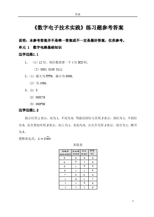
《数字电子技术实践》练习题参考答案说明:本参考答案并不是唯一答案或不一定是最好答案,仅供参考。
单元 1 数字电路基础知识 边学边练1.11、 (1)12位,每位数需要一个4位BCD 码。
(2)0001 0100 01112、(1)最大为FFFH ;最小为000H 。
(2)为4096。
3、(1) 5(2) 000C7H (3) 000F9H 边学边练1.2指示灯用L 表示,亮为1,不亮为0;驾驶员到位与否用D 表示,到位为1,不到位为0;安全带扣环用B 表示,扣上为1,未扣为0;点火开关用S 表示,闭合为1,断开为0。
逻辑表达式:S B D L真值表综合练习1、 C B A D B A C B A F ⋅⋅+⋅⋅+⋅⋅=2、DC BD A H D C B A D C B A D C B A D C B A G DC B AD C A B A F DC B A E ⋅⋅+⋅=⋅⋅⋅+⋅⋅⋅+⋅⋅⋅+⋅⋅⋅=⋅⋅⋅+⋅⋅+⋅=⋅⋅⋅=3、设逻辑变量A 、B 、C 、D 分别表示占有40%、30%、20%、10%股份的四个股东,各变量取值为1表示该股东投赞成票;F 表示表决结果,F =1表示表决通过。
F =AB +AC +BCD4、设A 、B 开关接至上方为1,接至下方为0;F 灯亮为1,灯灭为0。
F =A ⊙B5、设10kW 、15kW 、25kW 三台用电设备分别为A 、B 、C ,设15kW 和25kW 两台发电机组分别为Y 和Z ,且均用“0”表示不工作,用“1”表示工作。
CAB Z B A B A Y ⋅=⋅=6、 真值表逻辑函数式为:F =A +BD +BC7、输入为余3码,用A 、B 、C 、D 表示,输出为8421BCD 码,用Y 0、Y 1、Y 2、Y 3表示。
DC A B A Y C BD C B D B Y DC Y DY ⋅⋅+⋅=⋅+⋅⋅+⋅=⊕==32108、设红、绿、黄灯分别用A 、B 、C 表示,灯亮时为1,灯灭时为0;输出用F 表示,灯正常工作时为0,灯出现故障时为1。
- 1、下载文档前请自行甄别文档内容的完整性,平台不提供额外的编辑、内容补充、找答案等附加服务。
- 2、"仅部分预览"的文档,不可在线预览部分如存在完整性等问题,可反馈申请退款(可完整预览的文档不适用该条件!)。
- 3、如文档侵犯您的权益,请联系客服反馈,我们会尽快为您处理(人工客服工作时间:9:00-18:30)。
一、TTL测试
1.主要参数有哪些?测试参数的意义何在?
2.怎样测量与非门输出的高低电平?高低电平的取值范围?
3.测量Iil或Iolm时电流档不能用,怎么办?
4.在扇出系数测试电路中电位器和220欧电阻有什么用?为什么要使Uo=0.4V,此系数计算结果若为23.9,取多少?
二、组合逻辑电路
1、组合逻辑电路与时序逻辑电路的区别有哪些/?
2、设计组合逻辑电路的步骤。
3、设计半加器、全加器、比较器、点灯控制等逻辑电路。
三、译码器
1、什么是译码器?本实验用的74LS38和CC4511有什么区别?
2、怎样用138和74LS20设计全加器?步骤?
3、怎么用138设计反码器?
4、描述数码管种类、结构?
5、设计编码到译码显示的电路显示2014。
四、选择器
1、介绍四选一和八选一选择器的逻辑功能。
2、怎样用选择器实现逻辑函数或功能电路?
3、设计全加器或三人表决器。
五、触发器
1、画出用与非门构成基本QS触发器电路图。
2、叙述J-K触发器功能,填功能表。
3、描述T,T’触发器,CP-SQ脉冲关系。
六、计数器
1、怎样用D触发器构成四位数的二进制异步加法器、?讲解其工作原理,注意哪些事项?
2、讲述用74LS192构成二位十进制计数器电路。
3、用192构成任意进制计数器,讲解原理。
七、抢答器
1.讲述抢答器工作原理
2.锁存电路怎样锁存,主持人怎样控制清零和宣布抢答开始?
3.此实验原理电路存在哪些缺点和不足,怎样改进?
4.抢答器灵敏度与哪些因素有关?怎样分析影响。
八、数电常识
1、TTL逻辑门引脚规则。
2、TTL电源的范围
3、怎样使用集成块
4、数字电路故障原因通常有哪些?
5、边沿怎样产生的?能否用逻辑开关产生?
6、脉冲信号与函数波信号的区别?
7、TTL逻辑门输入端悬空相当于什么电平?
8、怎样由与非门变非门?
9、本学期数字电路接触了哪些集成块?
10、TTL集成电路使用规则?
数电实验答案
一、TTL测试:
1、主要参数有:(1)导通电源电流Iccl与截止电源电流Icch,它们的大小标志着与非门在静态情况下的功耗大小;
(2)低电平输入电流Iil与高电平输入电流Iih,它的大小关系到前级门的灌电流负载能力;
(3)扇出系数No,它的大小是指门电路能驱动同类门的个数;
(4)电压传输特性,通过电压传输特性可知道与非门的一些重要参数,如输出高电平,输出低电平,关门电平,开门电平,阀值电平及抗干扰容限等;
(5)平均传输延迟时间tpd,衡量电路开关速度。
2、通过逐点测试法测出电压传输特性读出与非门输出的高低电平,输出高电平大于等于2.4V,输出低电平小于等于0.4V。
3、通过测电压间接测电流
4、限流作用,因为输出低电平小于等于0.4V,23
二、组合逻辑电路:(P194)
1、时序逻辑电路具有记忆功能。
时序电路的特点是:输出不仅取决于当时的输入值,而且还与电路过去的状态有关,组合逻辑电路在逻辑功能上的特点是任意时刻的输出仅仅取决于该时刻的输入,与电路原来的状态无关。
2、(1)根据设计任务的要求,建立输入输出变量,并列真值表
(2)用逻辑代数或卡诺图化简法求出简化的逻辑表达式,并按实际选用逻辑门的类型,修改逻辑表达式
(3)根据逻辑表达式画出逻辑图
(4)用实验来验证设计的正确性
3、根据组合电路设计方法,首先列出半加器的真值表,见表
三、译码器:
1、译码器是将二进制翻译成输出端不同状态的元件;
74LS138有3个输入端(000~111)8种状态组合,8个输出端Y0`Y7只有一个输出端有效(低电平有效)
CC4511有4个输入端(0000~1111)16种组合状态,输出端7个高电平有效,有足够的电压4V可以驱动二极管发光,当二进制编码超过十进制的9时不能显示处于消隐状态,有防伪码功能。
2、
3、把使能端S作为数据输入,二进制编码所对应的输出端是反向关系。
4、
5、
四、数据选择器:(P205)
1、
当G=1时,电路不工作,无论输入什么,都输出为0
五、触发器1、
2、
3、
六、计数器:
七、抢答器:
八、数电常识:
1、左下角为1,逆时针排列。
2、5V左右,左右波动幅值的10%,4.5-5.5V.
3、在使用新的集成块时,需用力压使原来的八字形接近梯形;不能单手拔出,易弯使之损坏。
4、连接线内部断裂,接触不良;接线错误;设备问题
5、高低电平变化瞬间产生边沿,逻辑开关不能产生边沿现象(产生抖动)
低电平
6、
7、高电平
8、将与非门所有的输入端连接起来
9、3-8线译码器74LS38 七线译码驱动器CC4511
四选一数据选择器74LS153 八选一数据选择器74LS151
JK触发器74LS112 D触发器74LS74
十进制可逆计数器74LS192
抢答器74LS175
与非门74LS00 74LS10 74LS20
与门74LS08
或门74LS32 74LS86
或非门74LS02
10、接插集成块时,要认清定位标记,不得插反。