香港理工大学CAD-CAE Training Centre的全套教程 Tut05-perfume
香港理工大学课程
香港理工大学课程课程申请限期2009 年9 月入学Accountancy - BBA(Hons)5 Jun 09会计学(荣誉)工商管理学士学位Accounting and Finance - BBA(Hons)5 Jun 09会计及金融(荣誉)工商管理学士学位Applied Biology with Biotechnology - BSc(Hons)5 Jun 09应用生物兼生物科技(荣誉)理学士学位Biomedical Engineering - BSc(Hons)5 Jun 09生物医学工程(荣誉)理学士学位Building Engineering and Management - BSc(Hons)5 Jun 09建筑工程及管理学(荣誉)理学士学位Building Services Engineering - BEng(Hons)5 Jun 09屋宇设备工程学(荣誉)工学士学位Business Administration and Engineering - BBA(Hons) & BEng(Hons) (double5 Jun 09 degree)工商管理及工程学双学位课程Chemical Technology - BSc(Hons)5 Jun 09化学科技(荣誉)理学士学位Chinese and Bilingual Studies - BA(Hons)5 Jun 09中文及双语(荣誉)文学士学位Civil Engineering - BEng(Hons)5 Jun 09土木工程学(荣誉)工学士学位Computing - BSc(Hons) Scheme5 Jun 09电子计算(荣誉)理学士学位组合课程Computing and Management - BSc(Hons) & BBA(Hons) (double degree)5 Jun 09电子计算及管理学双学位(尚待批核)Design - BA(Hons)5 Jun 09设计学(荣誉)文学士学位Electrical Engineering - BEng(Hons)5 Jun 09电机工程学(荣誉)工学士学位Electronic and Information Engineering - BEng(Hons)5 Jun 09电子及资讯工程学(荣誉)工学士学位Engineering - BEng5 Jun 09 工学士学位Engineering Physics - BSc(Hons)5 Jun 09 工程物理学(荣誉)理学士学位English Studies for the Professions - BA(Hons)5 Jun 09 专业英文(荣誉)文学士学位Enterprise Engineering with Management - BSc(Hons)5 Jun 09 企业工程兼管理(荣誉)理学士学位Environment and Sustainable Development - BSc(Hons)5 Jun 09 环境与可持续发展(荣誉)理学士学位(尚待批核)Fashion and Textiles - BA(Hons) Scheme5 Jun 09 服装及纺织(荣誉)文学士学位组合课程Financial Services - BBA(Hons)5 Jun 09 金融服务(荣誉)工商管理学士学位Geomatics - BSc(Hons)5 Jun 09 测绘及地理资讯学(荣誉)理学士学位Global Supply Chain Management - BBA(Hons)5 Jun 09 全球供应链管理(荣誉)工商管理学士学位Hotel Management - BSc(Hons)5 Jun 09 酒店业管理(荣誉)理学士学位Industrial and Systems Engineering - BEng(Hons)5 Jun 09 工业及系统工程学(荣誉)工学士学位International Shipping and Transport Logistics - BBA(Hons)5 Jun 09 国际航运及物流管理(荣誉)工商管理学士学位Internet and Multimedia Technologies - BSc(Hons)5 Jun 09 互联网及多媒体科技(荣誉)理学士学位Investment Science - BSc(Hons)5 Jun 09 投资科学(荣誉)理学士学位Logistics Engineering and Management - BSc(Hons)5 Jun 09 物流工程及管理(荣誉)理学士学位Management - BBA(Hons)5 Jun 09 管理学(荣誉)工商管理学士学位Marketing - BBA(Hons)5 Jun 09 市场学(荣誉)工商管理学士学位Mechanical Engineering - BEng(Hons)5 Jun 09 机械工程学(荣誉)工学士学位Medical Laboratory Science - BSc(Hons)5 Jun 09 医疗化验科学(荣誉)理学士学位Mental Health Nursing - BSc(Hons)5 Jun 09 精神健康护理学(荣誉)理学士学位(尚待批核)Nursing - BSc(Hons)5 Jun 09 护理学(荣誉)理学士学位Optometry - BSc(Hons)5 Jun 09 眼科视光学(荣誉)理学士学位Physiotherapy - BSc(Hons)5 Jun 09 物理治疗学(荣誉)理学士学位Product Analysis and Engineering Design - BEng(Hons)5 Jun 09 产品分析及工程设计学(荣誉)工学士学位Product Engineering with Marketing - BEng(Hons)5 Jun 09 产品工程兼市场学(荣誉)工学士学位Property Management - BSc(Hons)5 Jun 09 物业管理学(荣誉)理学士学位Radiography - BSc(Hons)5 Jun 09 放射学(荣誉)理学士学位Social Policy and Administration - BA(Hons)5 Jun 09 社会政策及行政(荣誉)文学士学位Social Work - BA(Hons)5 Jun 09 社会工作(荣誉)文学士学位Surveying - BSc(Hons)5 Jun 09 测量学(荣誉)理学士学位Tourism Management - BSc(Hons)5 Jun 09 旅游业管理(荣誉)理学士学位Transportation Systems Engineering - BEng(Hons)运输系统工程学(荣誉)工学士学位(尚待批核)。
CAD/CAM技术全套教案 完整版授课电子教案 整本书电子讲义 教学讲义.docx

CAD/CAM技术全套教案完整版授课电子教案整本书电子讲义教学讲义().docx1、教案第1~2课时教学内容项目一认识CAD/CAM技术项目分析随着人们生活水平的提高,消费者的价值观正在发生结构性改变,呈现多样化和独特化特征,用户对产品质量,产品更新换代速度,产品从设计、制造和投放市场的周期都提出了越来越高的要求,为了适应这种改变,企业产品也向着多品种、小批量方向进展。
CAD/CAM技术是近30年来快速进展,并得到广泛应用的设计和制造自动化应用技术,它从根本上转变了过去从设计到产品的整个生产过程中的技术管理和工作方式,给设计和制造领域带来了深刻变革。
其进展与应用程度已经成为一个国家科技进步和工业现代2、化水平的重要标志之一。
教学过程课程导入一、组织教学〔2分钟〕整顿纪律、清点人数,稳定学生心情。
二、导入新课〔5分钟〕1.本课题的学习目的2.本课题学习及把握的主要内容3.本课题参阅的材料4.对本课题作业的要求相关学问一、认识数控加工1.数控加工过程2.数控机床组成〔1〕机床本体〔2〕CNC装置〔3〕输入/输出设备〔4〕伺服单元〔5〕驱动装置〔6〕可编程掌握器〔7〕测量装置3.数控加工主要特点〔1〕工序集中〔2〕自动化〔3〕柔性化高〔4〕能力强二、熟识CAD/CAM技术功能及应用1.CAD/CAM系统基本功能〔1〕图形3、显示功能〔2〕输入/输出功能〔3〕存储功能〔4〕交互功能〔人机接口〕2.CAD/CAM系统的主要任务〔1〕几何建模〔2〕计算分析〔3〕工程绘图〔4〕结构分析〔5〕优化设计〔6〕计算机帮助工艺过程设计〔CAPP〕〔7〕自动编程〔8〕模拟仿真〔9〕工程数据管理和信息传输与交换3.CAD/CAM的应用〔1〕CAD/CAM技术应用的必要性和迫切性〔2〕CAD/CAM技术的应用4.CAD/CAM技术基本概念〔1〕CAD 〔2〕CAPP〔3〕CAM〔4〕CAD/CAM集成系统〔5〕CAE三、了解CAD/CAM 技术进展历程1.CAD4、技术的进展〔1〕形成阶段〔2〕进展阶段〔3〕成熟阶段〔4〕集成阶段2.CAD技术的进展3.CAD/CAM一体化〔集成〕技术四、了解CAD/CAM技术在我国现状及进展趋势1.CAD/CAM技术在国内的应用现状〔1〕起步晚、市场份额小〔2〕应用范围窄、层次浅〔3〕功能单一、经济效益不突出2.CAD/CAM技术的进展趋势〔1〕CAD/CAM技术应与多媒体技术更好的结合〔2〕CAD/CAM系统应具有高度的开放性〔3〕CAD/CAM系统应具有高度的开放性〔4〕CAD/CAM系统应具备更强的智能性3.CAD/CAM技术在企业中的5、应用前景五、了解常用CAD/CAM软件1.国产软件〔1〕中望3D〔2〕SINOVATION2.国外CAD/CAM软件〔1〕UGNX〔2〕Pro/ENGINEER 〔3〕CATIA〔4〕MasterCAM系统复习思索见教材本项目最终的思索题第3~4课时教学内容项目二绘制轴套类零件工程图项目分析CAXA 数控车是北京数码大方科技股份有限公司在全新的数控加工平台上开发的数控车床加工编程和二维图形设计软件。
《AutoCAD》培训教学大纲

《计算机辅助设计AutoCAD》培训教学大纲培训对象:从事或将从事建筑、机械等方面设计的相关工作人员或计算机辅助设计的制图爱好者。
培训学时:72学时培训教材:《AutoCAD2002职业技能培训教程》(劳动和社会保障部全国计算机信息高新技术考试中心)考核方式:参加全国计算机信息高新技术考试。
一、课程的内容要求:学员通过该课程的学习,使学生掌握AutoCAD2005的基本使用,能够绘制简单的工程图及机械设计图纸。
二、教学方式学生上机独立操作,理论实操同时进行,重在实践操作。
二、教学内容第一单元基本绘图和编辑命令的使用。
重点:对与AutoCAD基本绘图和编辑命令的熟练程度。
1、AutoCAD 2002绘图工具的基本应用:能够利用绘图工具绘制直线、辅助线、圆和圆弧、椭圆和椭圆弧、多边形、多段线等图形。
2、AutoCAD 2002绘图编辑命令的应用:能够使用各种图形编辑命令,如移动、复制、旋转、修剪、阵列、镜像等命令编辑图形。
第二单元块的创建与使用。
重点:熟练创建、管理和使用块。
1、创建块和管理块文件:能够创建普通块及带属性的块,熟悉AutoCAD设计中心的使用。
2、插入块:正确插入带属性或不带属性的块,能够使用AutoCAD设计中心将图块库中的块插入到图形中。
第三单元平面精确绘图与尺寸标注重点:综合运用捕捉、极轴追踪、对象捕捉、对象追踪和坐标系,以及各种编辑命令来精确绘制图形。
1、设置绘图环境:建立合适的图限、捕捉及栅格,并按要求为不同的绘制对象设置图层。
2、精确绘图:使用对象捕捉、极轴追踪、对象追踪辅助定位,利用绘图工具和图形编辑命令按图形尺寸精确绘图。
3、尺寸标注:设置合适的尺寸标注样式,正确标注尺寸。
第四单元三维绘图与尺寸标注重点:会使用AutoCAD绘制三维图形,标注三维图形的尺寸,以及输出三维图形的多视图。
其中,绘制机械图形时的重点如下:1、设置绘图环境:建立合适的图限、捕捉及栅格,并按要求为不同的绘制对象设置图层。
CAD制图培训教材(共-36张)

绘 直 线
命令行: Line(L) 菜 单: [绘图]→[直线(L)] 工具栏: [绘图]→[直线] 命令选项 角度(A): 指直线与UCS的X轴的夹角 长度(L): 指两点之间的距离 跟踪(F): 跟踪最近画过的线或弧终点的切线方向,以便沿着这个方向继续画线 闭合(C): 将第一条直线段的起点和最后一条直线段的终点连接起来,形成一个封闭区域 撤销(U): 撤消最近绘制的一条直线段。重新输入U,点击【回车键】,则重新指定新的终点
图形绘制
编辑对象
区域填充
绘图工具
图层线型
绘制文字
尺寸标注
阵 列
命令行: Array(AR) 菜 单: [修改]→[阵列(A)] 工具栏: [修改]→[阵列] 复制选定对象的副本,并按指定的方式排列,输入命令后,对话框如下:
复 制
命令行: Copy(CP&CO) 菜 单: [修改]→[复制选择(Y)] 工具栏: [修改]→[复制对象] 复制当前选取的对象,作用同Ctrl+C
绘 圆
命令行: Circle(C) 菜单: [绘图]→[圆(C)] 工具栏: [绘图]→[圆] 命令选项 两点(2P): 通过指定圆直径上的两个点绘制圆 三点(3P): 通过指定圆周上的三个点来绘制圆 T(切点、切点、半径): 通过指定相切的两个对象和半径来绘制圆 弧线(A): 将选定的弧线转化为圆 多次(M): 选择“多次”选项,将连续绘制多个相同设置的圆 常输入C后,点击鼠标左键,选择输入半径来绘圆
绘图工具
图层线型
绘制文字
尺寸标注
绘 射 线
命令行: Ray 菜 单: [绘图]→[射线(R)] 命令选项 等分(B): 垂直于已知对象或平分已知对象绘制等分射线 水平(H): 平行于当前UCS 的X 轴绘制水平射线 竖直(V): 平行于当前UCS 的Y 轴绘制垂直射线 角度(A): 指定角度绘制带有角度的射线 偏移(P): 以指定距离将选取的对象偏移并复制,使对象副本与原对象平行 主要用于绘制时进行比对和平移等,使用较少
CAD2024入门级教程(全套98节课)

它具有强大的绘图、编辑、分析和输出功能,能够 帮助用户高效地完成各种设计任务。
03
CAD2024支持多种文件格式,具有良好的兼容性和 扩展性,可以满足不同用户的需求。
界面布局与功能区域
菜单栏
包含文件、编辑、视图、格式 、工具等菜单项,用于执行各 种命令。
绘图区
用于显示和编辑图形的主要区 域。
标题栏
显示软件名称和当前文件名称 。
工具栏
提供常用命令的快捷方式,方 便用户快速操作。
状态栏
显示当前光标位置、绘图模式 等信息。
基本操作与设置
01
启动与退出
介绍如何启动和退出CAD2024软件 。
系统设置
介绍如何设置绘图单位、精度、背 景颜色等参数。
03
02
文件操作
讲解如何新建、打开、保存和关闭 文件。
尺寸修改与调整
阐述如何对已有的尺寸标注进行修改和调整 ,包括修改尺寸数值、调整尺寸位置和方向 等操作。
选择集与夹点编辑功能
选择集构建
介绍在CAD中构建选择集的多种方法,如单选、框选、交叉选择等 ,以及如何利用选择过滤器快速筛选目标对象。
夹点编辑功能
详细讲解CAD的夹点编辑功能,包括拉伸、移动、旋转等操作,以 及如何利用夹点实现快速编辑和修改图形对象。
详细讲解如何设置布局参数,如纸张大小、 边距等,并介绍如何管理不同视图。
图层管理与显示控制
探讨图层在布局中的应用,以及如何控制图 层的显示与隐藏。
打印参数配置和输出设备选择
打印参数详解
深入解析打印参数,包括打印范围、比例、 线宽等,确保输出效果符合预期。
输出设备选择与配置
介绍如何选择适合的打印设备,并讲解设备 的配置方法。
CAA入门培训
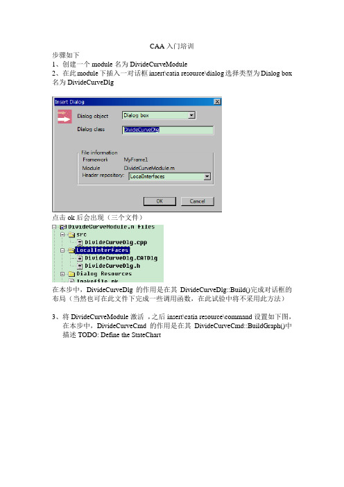
CAA入门培训步骤如下1、创建一个module名为DivideCurveModule2、在此module下插入一对话框insert\catia resource\dialog选择类型为Dialog box 名为DivideCurveDlg点击ok后会出现(三个文件)在本步中,DivideCurveDlg的作用是在其DivideCurveDlg::Build()完成对话框的布局(当然也可在此文件下完成一些调用函数,在此试验中将不采用此方法)3、将DivideCurveModule激活,之后insert\catia resource\command设置如下图,在本步中,DivideCurveCmd的作用是在其DivideCurveCmd::BuildGraph()中描述TODO: Define the StateChart4、插入Addin。
激活MyFrame1新建一个module名为DivideCurveAddinModule,在此module下insert\component,设置如下(名为DivideCurveAddin接口类型CATIPrtWksAddin(个人认为即在part中的Addin))(需要注意的是第二个图将下面的选项去掉)5、创建工具条在DivideCurveAddin.h中添加两个Public函数声明:void CreateCommands();CATCmdContainer * CreateToolbars();在DivideCurveAddin.cpp中添加下面代码//下面为添加内容//CATApplicationFrame#include "CATCommandHeader.h"//下面用到了MacDeclareHeader#include "CATCreateWorkshop.h"// 下面用到了NewAccess等#include "CATCmdContainer.h"// 下面用到了CATCmdContainerMacDeclareHeader(DivideCurveCmdHeader);//定义一个标签类DivideCurveCmdHeader//-------------------------------------------------------------------------//CreateToolbars//-------------------------------------------------------------------------CA TCmdContainer * DivideCurveAddin:: CreateToolbars (){//To create a toolbar. Then use the AddToolbarView macro to declare the new toolbar. CA TCmdWorkshopNewAccess(CATCmdContainer,pCAAAfrOperationTlb,CAAAfrOperationTlb);AddToolbarView(pCAAAfrOperationTlb,1,Right); // visible toolbar// To create a starter. Then to attach a command header to this starter use the SetAccessCommand macroNewAccess(CATCmdStarter,pCAAMfrDivideCurveStr,CAAMfrDivideCurveStr);SetAccessCommand(pCAAMfrDivideCurveStr,"CAAMfrDivideCurveHeader");SetAccessChild(pCAAAfrOperationTlb,pCAAMfrDivideCurveStr);return pCAAAfrOperationTlb ;}//-------------------------------------------------------------------------//CreateCommands//-------------------------------------------------------------------------void DivideCurveAddin:: CreateCommands (){new DivideCurveCmdHeader ("CAAMfrDivideCurveHeader","DivideCurveModule","DivideCurveCmd",(void *)NULL);//参照命令标签ID的命名}在imakefile中添加LINK_WITH = $(WIZARD_LINK_MODULES)\CATApplicationFrame此时即可编译,可能会有错误,仔细排查如# mkmk-WARNING: MyFrame1\DivideCurveModule.m -> Module [CATMathStream.m], which is define as an alias, was automatically added in LINK_WITH.即需要在DivideCurveModule.m下的imakefile中添加LINK_WITH = $(WIZARD_LINK_MODULES)\CA TMathStream另外,有时即使加入LINK_WITH,也会提醒## start step: DataUpdate at 07/14/2010-16:02:43#mkmk-WARNING:DivideCurveFrame\DivideCurveAddinModule.m -> Module [CA TConstraintModelerUI.m], automatically added in LINK_WITH, is used although it is in framework [D:\CATIA\B13\.\ConstraintModelerUI] which is not a direct prerequisite.# mkmk-ERROR:DivideCurveFrame\DivideCurveAddinModule.m -> Module [CA TConstraintModelerUI.m] in LINK_WITH is ignored since it is in framework [D:\CA TIA\B13\.\ConstraintModelerUI] which is not a direct prerequisite.这是需要LINK_WITH = $(WIZARD_LINK_MODULES) \CATConstraintModelerUI在Identitycard.h中加入:AddPrereqComponent("ConstraintModelerUI",Protected);运行结果如下或6、上面点击后没有响应,下面要做的即点击后弹出一对话框与实现此功能只要在void DivideCurveCmd::BuildGraph()中添加以下代码即可(当然首先把其中的代码删掉、构造函数中代理_Indication(NULL)删掉、.h中的CATIndicationAgent * _Indication;删掉,总之将自动生成的有关代理_Indication全部删掉)在函数void DivideCurveCmd::BuildGraph()实现以下功能(1)创建一对话框(2)描述state chart。
CADCAM学习指导教程
CAD/CAM学习指导教程(二)刘振江装备制造工程分院数控教研室2010年3月8日四、实体造型实例【例4-1】 绘制如图4-1所示的实体。
图4-1 支撑座实体【操作步骤】(1)绘制底座草图①按 XOY 面作为视图平面和作图平面。
②按③单击“曲线生成栏”工具条中的“矩形”按钮 ,在左侧的立即菜单中选取“中心_长_宽”方式,设置长度为200、宽度为100。
拾取坐标原点作为矩形的中心点,单击鼠标右键结束命令,完成后的图形如图4-2所示。
图4-2 绘制矩形图 ④单击“曲线生成栏”工具条中的“整圆”按钮 ,在左侧的立即菜单中选择“圆心_半径”方式。
拾取圆心点(坐标原点),再拾取矩形的一个角点作为圆的圆周上一点,单击鼠标右键结束命 令,完成后的图形如图4-3所示。
⑤单击“线面编辑栏”工具条中的“曲线裁剪”按钮 ,在左侧的立即菜单中选择快速裁剪和正常裁剪,拾取需要裁剪的地 方,裁剪完成后的图形如图4-4所示。
4-3 绘制整圆图4-4 修剪图形 图4-5 删除多余线条⑥单击“线面编辑栏”工具条中的“删除”按钮,删除两边的直线,完成后的图形如图4-5所示。
⑦按(2)生成底座单击“特征生成栏”工具条中的“拉伸增料”按钮,在弹出的“拉伸增料”对话框中设置类型为固定深度,设置深度为20,在拉伸对象中拾取刚刚绘制的草图,选择“拉伸为”中的实体特征,单击“确定”按钮,如图4-6所示。
生成后的实体如图4-7所示。
图4-6 “拉伸增料”对话框图4-7 生成底座(3)生成通槽①选择实体上表面作为绘图表面,按F2键,激活草图绘制模式。
②单击“曲线生成栏”工具条中的“相关线”按钮,在左侧的立即菜单中选择实体边界,拾取上表面边界(两个圆弧,两条直线),生成实体边界。
③单击“曲线生成栏”工具条中的“等距线”按钮,在左侧的立即菜单中设置等距的距离为10,拾取上表面的直线,此时系统提示选方向,在所选图形的内部单击鼠标左键,完成两条直线的生成,如图4-8所示。
CAE培训学习教程
模态分析 ——用于计算结构的固 有
频率和模态。
谱分析 ——是模态分析的扩展, 用
于计算由于随机振动引起的结构
位
第23页/共45页
一、 CAE与FEM
谐波分析 —— 确定线性结构对随 时
间按正弦曲线变化的载荷的响应.
瞬态分析 —— 确定结构对随时间 任
意变化的载荷的响应. 可以考虑 与静
有限元模型
第4页/共45页
一、 CAE与FEM
载荷 约束
节点: 空间中的坐标位置,具有一定自由度和 存在相互物理作用。
单元: 一组节点自由度间相互作用的数值、矩阵 描述(称为刚度或系数矩阵)。单元有线、 面或实体以及二维或三维的单元等种类。
有限元模型由一些简单形状的单元组成,单元之间通过节点连 接,并承受一定载荷和约束。
一、 CAE与FEM
CAE
FEM
BEM
SEA
MB
第2页/共45页
一、 CAE与FEM
2、FEM概念
Finite Element Method, 即有限单元法。是对物理现象 (几何及载荷工况)的模拟,是对真实情况的数值近似。通 定义 过划分单元,求解有限个数值来近似模拟真实环境的无限个 未知量。
历史典故
弹性部件 杆、梁狭长件
薄壳部件 所有分析对象
流体单元
空气、水
… …
第13页/共45页
一、 CAE与FEM
: 单元选择准则
准则
• 在结构分析中,结构的应力状态决定单元类型的选择。 • 选择维数最低的单元去获得预期的结果 (尽量做到能选择点而不
选择线,能选择线而不选择平面,能选择平面而不选择壳,能 选择壳而不选择三维实体). • 对于复杂结构,应当考虑建立两个或者更多的不同复杂程度的 模型。你可以建立简单模型,对结构承载状态或采用不同分析 选项作实验性探讨。 • 在许多情况下,相同的网格划分,采用更高阶类型的单元可以 得到更好的计算结果,但计算时间会增加。
香港理工大学CAD-CAE Training Centre的培训教程-L6-Digital Mockup
CATIA V5 Digital Mockup (DMU) Version 5 Release 16DMU FittingDMU KinematicsDMU FittingS imulate part motions for assembly and maintainability issuesA.DMU Simulation : Key tools for DMU FittingB.DMU Check : Measure Interference, distance, detect Clash while movingC.Manipulation : Manipulate model or Compass while creating a trackD.Recorder : Record or modify the trackE.Player:Play the trackA CDBEToolbarsOpen an Assembly Document Create a TrackRepeat creating tracks for other components Create a Sequence of TracksAnalyze the results and modify the design if necessaryGeneral ProcessDetect Clashes automatically during the part movement:-Three modes are available:(1)On(default mode), which deactivates clash detection(2)Off, which highlights in the geometry area products incollision while playing a simulation(3)Stop, which stops the simulation when the first clash isdetected.Measure distances AFTER a simulation:--Click “Distance”icon-Select two components-Click “Apply”to get the minimum distanceMeasure distances DURING a simulation:--After “Distance.1”is created, double-click “Sequence.1”on the tree-Select the Tab Page “Edit Analysis”-Put “Distance.1”on the list called “Analyses in Sequence”-Set it ActiveOn/ Off/ Stop(1) File Open:-•File/Open/Excavator_a.CATProduct(2) Change workbench to DMU Fitting:-•If the current workbench is not “DMU Fitting”, select “Start/Digital Mockup/ DMU fitting”onthe top menu to change. (otherwise, it needn’tchange)(3) Make the 1st Film:-•Click “Track”icon•Select Upper_Assm(Upper_Assm.1) on tree •(The Compass will be snapped onto the assembly and it will turn GREEN)(3) Cont’:-•Drag the upper assembly out by Compass •Then Click “Record(Insert)”icon to record the new position•Drag the assembly to another position •Click “Record(Insert)”icon again•Click ok complete(4) Repeat Step 3 to make the remainingFilms for the below components:-•Bucket•Front_Arm•Back_Arm•Arm_Support•Cabinet•Engine•Exhaust(5) Create a Play Sequence of the films:-•Click “Edit Sequence”icon•Select Track.1 under the list of “Action in session”•Click•Select Track.2, then•…Repeat the steps until all Tracks are inserted(6) Play the Sequence of films:-•Click “Simulation Player”icon•Select Sequence.1•(The Player is activated on top of the screen)•Click “Parameters”icon•Enter 5s as Sampling Step (Run the simulation faster)•Click(6) Cont’:-•Click “Change Loop Mode ”icon to run the simulation continuously •Click “Stop”icon to stop•Click “Simulation Player ”icon again to exit(7) Reset the positions:-•Click “Reset Position ”icon•(all components will be back to their original positions)(8) Hide all Track Lines on screen:-•Right-Click “Tracks”on the tree •Select “Hide/Show”Change Loop ModeStop(9) Refine Environment Settings (optional):-•To improve the resolution, select“Tools/options…/General/Display/Performances/3D Accuracy/Fixed”on the top menu andchange it to 0.01(smallest value)•Change the shading mode to “Shading withMaterial”•Select “View/Render Style/Perspective”on the menu•Select “View/ Lighting…”and then select “Two Lights”•To Hide Compass, Deselect “View/ Compass”on the top menu•To Hide Tree, Deselect “View/ Specifications”on the top menu(10) Export Simulation into AVI format•Click “Tools/Simulation/Generate Video”onthe top menu•Select Sequence.1 on tree•Select “VFW Codec”as default•Click “Setup”button and select “CinepakCodec by Radius”as Compressor•Click “File name…”to define the destinationof the exported file and the file name•Click ok to complete(Remark: During the conversion, we can manipulatethe geometry by mouse)END of Exercise 1DMU KinematicsS imulate the mechanism of an assemblyA.DMU Kinematics : Key tools for DMU KinematicsB.Simulation : Make Simulation with commandsC.Kinematics Joints : Create Joints between componentsD.Kinematics Update : Restore or Update positions of componentsE.DMU Generic Animation:Record or Export Simulation into other formatDEOpen an Assembly DocumentDelete all Constraints & Create Joints manually -Or-Browse the Mechanism with CommandsCreate a SimulationAnalyze the results and modify the design if necessaryGeneral ProcessScissor Jack-Create Kinematic Joints-Simulate the mechanism with command-Study the mechanism behavior (Displacement and Speed) (1)File/Open/Scissorjack_a.CATProductUpperArm (x2) ScrewBaseLowerArm (x2)MidJointMid Nut(2) Change workbench to DMU kinematics:-•If the current workbench is not “DMUkinematics”, select “Start/Digital Mockup/DMU kinematics”on the top menu to change.(otherwise, it needn’t change)(3) Delete all Constraints:-•Right-Click on “Constraints”on the product tree and then select “Delete”•(We are going to create kinematic jointsmanually. Once a joint is created between twoparts, the corresponding constraints will bemade automatically between them. To preventredundancy, we need to delete all theconstraints, which were made on the“Assembly Design”workbench, before creatingjoints.)(4) Fix “Base”in place:-•Select “Fixed Part”icon•Click “New Mechanism”icon on the pop-upwindow•Click ok to accept the default name•Select “Base”(by clicking “Base”on tree or clicking on the geometry directly)•(A Fix Constraint is created automatically, and at the same time, a fixed part is defined inMechanism.1)(5) Create a Revolute joint between RightLower Arm and Base:-•Select “Revolute Joint”icon•Click Axis of LowerArm and then Axis of Base (Put the mouse cursor onto the cylindrical surface toget its axis)•Click Face of LowerArm and then Face of Base •Click ok to completeArm and Base:-•Select “Revolute Joint”icon•Click Axis of LowerArm and then Axis of Base •Click Face of LowerArm and then Face of Base •Click ok to complete(7) Create a Revolute joint between Right•Click Axis of LowerArm and then Axis of UpperArm •Click Face of LowerArm and then Face ofUpperArm•Click ok to completeArm and Left Upper Arm:-•Select “Revolute Joint”icon•Click Axis of LowerArm and then Axis of UpperArm •Click Face of LowerArm and then Face ofUpperArm•Click ok to completeUpper Arm and Top:-•Select “Revolute Joint”icon•Click Axis of UpperArm and then Axis of Top•Click Face of UpperArm and then Face of Top•Click ok to completeUpper Arm and Top:-•Select “Revolute Joint”icon•Click Axis of UpperArm and then Axis of Top •Click Face of UpperArm and then Face of Top•Click ok to completeUpper Arm and Mid-Nut:-•Select “Revolute Joint”icon•Click Axis of UpperArm and then Axis of MidNut •Click Face of UpperArm and then Face of MidNut•Click ok to complete(12) Create a Revolute joint between RightUpper Arm and Mid-Joint:-•Select “Revolute Joint”icon•Click Axis of UpperArm and then Axis of Midjoint •Click Face of UpperArm and then Face of MidJoint •Click ok to complete(13) Create a Revolute joint between Mid-Jointand Screw:-•Drag the Screw out of the hole by Compass •Show xy-plane, yz-plane & zx plane of Mid-Joint •Select “Revolute Joint”icon•Click Axis of Mid-Joint and then Axis of Screw •Click zx Plane of Mid-Joint and then Face of Screw •Enter 10mm as Offset•Click ok to completeSelect this planar face(14) Create a Screw joint between Mid-Nut andScrew:-•Drag the Screw out of the hole by Compass again so that we can see the screw hole•Select “Screw Joint”icon•Click Axis of MidNut and then Axis of Screw •Select “angle driven”option•Enter 1as Pitch•Click ok to complete(15) Create a Gear joint between Right LowerArm and Left Lower Arm:-•Select “Gear Joint”icon•Select Revolute.1 and then Revolute.2•Select Opposite as Rotation Directions•Click ok to complete(16) Create a Gear joint between Right UpperArm and Left Upper Arm:-•Select “Gear Joint ”icon •Select Revolute.5 and then Revolute.6•Select Opposite as Rotation Directions •Click ok to complete(Finally, a window pops up, saying that the mechanismcan be simulated)Gear.2Gear.1screwRevolute.4Revolute.7Revolute.6Revolute.5Revolute.9Revolute.8(17) Hide all Constraints:-•Right-Click on “Constraints”on the product tree and then select “Hide/Show”(18) Simulate the Mechanism:-•Select “Simulation with Commands”icon •Click “…”button next to Command.1•Enter -30000 as Lowest Value•Enter 30000 as Highest Value•Click ok to confirm•Select “Immediate”Simulation•Put the mouse cursor onto the screw (double-arrow appears)•Press and Hold the Right Button to rotate the screw (The whole mechanism moves)(19) Get the Smallest Height of Scissor Jack:-•Select “Activate Sensors ”option (another menupops-up)•Select the third button “Stop when Clash”•Select “On Request”Simulation•Select 40 as Number of steps•Adjust Command.1 to -30000 (lowest value)•Click “Play”icon•(The mechanism moves until the clash occurs;When Command.1 is ~21000, it stops)•Select “Close”on both menus(20) Reset Command.1 to Zero:-•Double-Click Command.1 on tree•Click “Reset to Zero ”button•Click ok to complete•(Now when Command.1=0 deg, the scissor jack isthe shortest)It is now fully contracted(21) Define the relation between Command.1and Time:-•Click “Formula”icon•Click Mechanism.1 on tree•(Two related parameters are sorted out:“Mechanism.1\KINTime”&“Mechanism.1\Commands\Command.1\Angle”)•Select“Mechanism.1\Commands\Command.1\Angle”•Click “Add Formula”button•Enter (Mechanism.1\KINTime /1s)*360*2deg•Click ok•Click ok again•(The formula is now stored under Mechanism.1)(22) Define a Sensor:-•Click “Speed and Acceleration”icon ••face as Point Selection•Select “Main axis”•(Remark: “Main Axis”is the axissystem of the Product, which is alsothe axis system of Base (1stcomponent))•Click ok to complete(23) Run the Simulation withFormula:-•Click “Simulation with Laws”icon(23) Con’t:-•Select “Activate Sensors”•Select “Speed-Acceleration.1\z_vertex”and “Speed-Acceleration.1\z_LinearSpeed”•Click “Stop when Clash”button•Click “…”button•Enter 200s as Maximum time bound •Click ok•(The mechanism moves, but stops at ~130s when clash is detected)(24) Study Results:-•Click “Graphics…”button•We get two curves on the graph:Yellow –Displacement of the Top Face;Green –Speed of the Top Face•Smallest Height = 95mm•Largest Height = 326mm•Range = (326-95) = 231mm•Total Time (from Full contraction to Full Extension) = 133sec (assuming the angularspeed of the screw is 2 rev/sec)(25) Restore original positions:-•Click “Reset Positions”button。
CAE培训教程
CAE培训教程CAE (Computer-Aided Engineering) 培训教程引言:在当今快速发展的科技领域中,计算机辅助工程(CAE) 已成为提高产品设计和分析效率的重要工具。
CAE 引入了一系列的软件和模拟技术,可以帮助工程师们进行复杂的设计和分析任务。
本文档将介绍CAE 培训教程的重要性以及如何选择和使用相应的培训资源。
同时,我们还会深入探讨几个流行的CAE 软件供应商和他们的培训课程。
第一部分:CAE 培训教程的重要性1.1 提高工程师技能:CAE 培训教程通过教授各种软件的使用和工程原理,可以提高工程师们的技能和知识水平。
这将使他们能够更加高效地进行产品设计和分析,并且从中获得更准确和可靠的结果。
1.2提高生产力和效率:CAE 培训教程将提供如何使用CAE 软件的详细指导。
这将有助于提高工程师们的工作效率,并减少错误和重复工作。
此外,通过模拟和分析,可以在设计早期发现潜在的问题,从而节省时间和费用。
1.3 投资回报率:培训工程师们使用CAE 软件是一个长期投资。
准确的设计和分析可以减少产品开发周期并提高产品质量。
这将为企业带来较高的投资回报率。
第二部分:选择适合的CAE 培训教程 2.1 考虑个人需求:在选择CAE 培训教程之前,工程师们需要先考虑自己的需求和目标。
他们可以问自己以下问题:- 我需要掌握哪些CAE软件?- 我想学习哪些特定的工程原理和技术?- 我的时间和预算允许我参加哪种类型的培训?2.2 培训供应商和资源:CAE 培训教程可以通过多种方式获取,比如在线课程、培训中心、私人培训等。
工程师们可以在以下资源中选择合适的培训供应商:- 软件供应商:大多数CAE 软件供应商都提供相关的培训课程。
他们的培训通常会覆盖软件的基本功能和高级特性,并以应用案例来帮助学生更好地理解。
- 培训中心:一些专门的培训中心也提供了CAE 培训。
这些中心通常会有更深入的教学内容和实践环境,可以提供更综合的学习体验。
- 1、下载文档前请自行甄别文档内容的完整性,平台不提供额外的编辑、内容补充、找答案等附加服务。
- 2、"仅部分预览"的文档,不可在线预览部分如存在完整性等问题,可反馈申请退款(可完整预览的文档不适用该条件!)。
- 3、如文档侵犯您的权益,请联系客服反馈,我们会尽快为您处理(人工客服工作时间:9:00-18:30)。
CATIA V5 Surface-modeling (Tutorial 5-Perfume Bottle)GSD (Surface-modeling)CATIA Surface-modelingTutorial 5A–Import a 2D outline drawing into Catia–Build 3D curves based on the imported drawing–Build the “right wing”of the perfume bottle (byGenerative Shape Design)Tutorial 5B–Continue to build the remaining outer faces–Close all the openings except the bottle mouth–Apply a material texturePlease be reminded that this series of tutorials is designed to demonstrate a design approach with CATIA, rather than the command itself.•Create a new project folder and copy this drawing file (your DVD name):\Model\perfume_outline.dxf)into the folder•Enter CATIA by double-clicking its icon on the desktop •(If the license menu pops up, select ED2and close CATIA.Then reopen again)•By default, an empty “Product”file is created. But now, you don’t need this, just select “File/Close”on the menu bar •Select “File/Open”on the menu bar and select thedrawing (perfume_outline.dxf)•Click “Dimensions”icon;•Click the highest line and then the lowest line on the front view to measure the height;•Check if the displayed dimension is 150.5mm; If not, we need to enlarge or shrink the drawing intothe correct size.•Multi-select all entities on the drawing;•Click “Copy”icon (or “Ctrl C”on keyboard).•Select “File/New”on the menu bar;•Select “Part”as the Type;•Enter “Perfume_bottle”as part name;•Leave the two options “Enable hybrid design”& “Create a geometrical set”unchecked; now anew empty part is created.•(To confirm that Hybrid Design is not activated),select Tools/Options/infrastructure/PartInfrastructure…then confirm that the option“Enable Hybrid Design inside part bodiesand bodies”is NOT SELECTED.•Check if the current workbench has been“Generative Shape Design”. You can see theworkbench icon at the upper right-hand corner.•If the current workbench is “Part Design”for example, select “Start/Shape/GenerativeShape Design”on the menu bar.•Select “Insert/Geometrical Set…”on themenu bar; then click ok to confirm; (Thisgeometrical set is going to store all fivereference views of the perfume bottle).•Click “Sketch”icon and select xy plane;•Click “Paste”icon to paste the drawing onto the xy plane;•Click “Exit”icon to exit the sketcher mode.(Now “Sketch.1”is stored in “GeometricalSet.1”)To split the drawing into five individual views and then position them:-•Duplicate FOUR more “Sketch.1”by copy-and-paste;•Rename them as “Bottom View”, “Section View1”“Section View2”, “Front View”& “RightView”.•Click “Plane”icon;•Select “offset from plane”as type;•Pick “XY plane”as reference;•Enter -200mm as offset value;•Click ok to confirm.•Create an offset plane, -250mm from XY plane;•Create an offset plane, -300mm from XY plane;•Create an offset plane, 200mm from YZ plane;•Create an offset plane, 200mm from ZX plane;•Right-click on “Bottom View”on the tree and select “Top View object/ Change SketchSupport”;•Select “Plane.1”;•Click ok to confirm.•Similarly, right-click “Section View1”and select “Change Sketch Support”;•Select “Plane.2”;•Similarly,•“Section View2” “Plane.3”•“Front View” “Plane.4”•“Right View” “Plane.5”•Double-click “Bottom View ”sketch on the treeto edit;•Select and delete the curves not related to thebottom view;•(After deletion, you can still see curves at thesame position, but they belong to the othersketches “Section View1”& Section View2”.)•Select all elements of the profile and then click“Translate ”icon;•Leave “Duplicate mode”unchecked;••Then Click the origin of the sketch. (Now thebottom view is relocated at the origin);•Click “Exit ”to complete.12originSimilarly, we can modify “Section View1”…•Double-click “Section View1”sketch on thetree to edit;•Select and delete the curves not related to this view;•Select all elements and then click “Translate”icon;•Leave “Duplicate mode”unchecked;••Then Click the origin of the sketch. (Now the “section view1”is relocated at the origin);•Click “Exit”to complete.2Similarly, we can modify “Section View2”…•Double-click “Section View2”sketch on the tree to edit;•Select and delete the curves not related to this view;•Select all elements and then click “Translate ”icon;•Leave “Duplicate mode”unchecked;••Then Click the origin of the sketch. (Now the “section view2”is relocated at the origin);•Click “Exit ”to complete.Similarly, we can modify “Front View”…•Right-click the “Front View”sketch on the tree andselect “Change Sketch Support”;•Select “Positioned”as Type of sketch positioning;•(Select “Implicit”as both Origin Type & OrientationType);•Click ok to confirm.•Double-click “Front View”sketch on the tree to edit;•Select and delete the curves not related to this view;•Select all elements and then click “Translate”icon;•Leave “Duplicate mode”••Then Click the origin of the sketch. (Now the “FrontView”is relocated at the origin);•Click “Exit”to complete.originSimilarly, we can modify “Right View”…•Right-click the “Right View”sketch on the tree and select “Change Sketch Support”;•Select “Positioned”as Type of sketch positioning;•(Select “Implicit”as both Origin Type & Orientation Type);•Click ok to confirm.•Double-click “Right View”sketch on the tree to edit;•Select and delete the curves not related to this view;•Select all elements and then click “Translate”icon;•Leave “Duplicate mode”••Then Click the origin of the sketch. (Now the “Right View”is relocated at the origin);•Click “Exit”to complete.Wrong orientation•(At this moment, we can see that “Bottom View”, “Section View1”& “Section View2”are at wrong orientation.)•Right-click the “Bottom View”sketch on the tree and select “Change Sketch Support ”;•Select “Positioned ”as Type of sketch positioning;•(Select “Implicit ”as both Origin Type & Orientation Type);•Select “Swap”•Click ok to confirm.•Similarly, “Swap”H-V axis for “Section View1”& “Section View2”respectively.•(Now we have positioned the five views at the correct places. These will be a good reference for us to build the 3D in the middle of the screen.)•(You can click any standard view icon to change viewing direction so that you can compare your working 3D with the reference at a specific viewpoint.)•Hide “Plane1”, “Plane2”, “Plane3”, “Plane4”& “Plane5”.•Right-click “Geometrical Set.1”on the tree and select “Properties”;•Enter “Reference ”as Feature Name;•Deselect “Pickable ”option (We treat them as the background images only);•Click ok to confirm.•(Optional) Multi-select all sketches, right-click to select “properties”, then change the line color to yellow .Tutorial 5AhideSection view1Section view2To create 3D curves from the reference sketches:-•Select “Insert/Geometrical Set…”on the menu bar (we are going to build a new folder to store new wireframe&surface elements);•Click ok to confirm.•Click “Plane”icon;•Select XY plane;•Click “Front View“icon;•(Select “Offset from Plane”as plane type);•Move the mouse cursor onto the green double arrow•(Offset value should be ~ 6mm)•Click ok to confirm.Tutorial 5ADrag theplane down•Click “Sketch ”icon and select “Plane.6”;•Draw a line as shown, referring to the background reference;•Select the line and click “mirror”icon , then click the y-axis•Click “connect”icon , click the two endpoints to build a connecting curve (check if the tangency direction is correct or not)•(if the tangency direction is wrong, double-click the curve and reverse the direction)•Click “Exit ”icon to complete.Tutorial 5AStop infront of this filletStop here, in front of this sharp cornerlineConnecting Line(mirrored)correctwrong•Click “Sketch ”icon and select “YZ plane ”;•Draw a line as shown, referring to the background reference;•Rotate the view a little bit (by the middle button & the right button of your mouse) to have an isometric view;•the icon (constraints defined in a dialog box) •Select “Coincidence”and ok;•Click “Normal View”icon and adjust the line to match the background reference as much as possible.•Click “Exit ”icon to complete.Tutorial 5ADraw a little bit longer beyond the spline curveAdjust the line to match the background reference•Select “Sketch.7”on tree, then press “Ctrl C”on the keyboard to copy;•Press “Ctrl V”to paste by 6 TIMES(6 moreidentical sketches are created on tree, i.e. “sketch.8”to “13”.•Double-click “Sketch.8”;•Adjust the line to match the background reference •Click exit to complete•Similarly, edit “Sketch9”, “Sketch10”, “Sketch11”, “Sketch12”& “Sketch13”tomatch the reference.Copy and paste to make 6 moreidentical sketchesSketch13Sketch12Sketch11Sketch10Sketch9Sketch8Sketch7 Result•Rotate the view a little bit (by the middle button & the right button of your mouse) to have anisometric view;•the icon (constraints defined in a dialogbox)•Click “Normal View”icon and adjust the spline tomatch the background reference as much aspossible.•Click “Exit”icon to complete.•Click “Sketch ”icon and select “ZX Plane ”;•Draw a spline (3 points) as shown, referring to the background reference;•Rotate the view a little bit;•icon (constraints defined in a dialog box) •Select “Coincidence”and ok;•Select the spline and click “mirror”icon , then click the y-axis;•Click “connect”icon , click the two endpoints to build a connecting curve; (check if the tangency direction is correct or not)•(if the tangency direction is wrong, double-click the curve and reverse the direction)•Double-click “connect”curve, adjust the tensions to match the reference (e.g. tension =2);•Click “Exit ”icon to complete.Tutorial 5AStop infront of this Spline ConnectingcurveSpline•Select “Sketch.15”(the previous sketch) on tree, then press “Ctrl C ”on the keyboard to copy•Press “Ctrl V ”to paste 7 TIMES (7 more identical sketches will be created on tree, i.e. “sketch.16”to “22”)•Double-click “Sketch.16”;•Adjust the curves to match the background reference;•Click exit to complete.Similarly, edit “Sketch17”, “Sketch18”,“Sketch19”, “Sketch20”,“Sketch21”& “Sketch22”to match the referenceCopy and paste to make 7 moreidentical sketchesSketch22Sketch21Sketch20Sketch19Sketch18Sketch17Sketch16Sketch15ResultTo Create a “Combine”Curve:-•Click “Combine”icon;•Select “Sketch.7”& “Sketch.15”;•Click ok to confirm.•(The new curve can fit the shape on both front view and right view)•Repeat the steps for the below combinations:•Hide Sketch 7 to Sketch22Sketch22Sketch21Sketch20Sketch19Sketch18Sketch17Sketch16Sketch15Sketch14Sketch13Sketch12Sketch11Sketch10Sketch9Sketch8Sketch7Sketch8 –Sketch16Sketch9 –Sketch17Sketch10 –Sketch18Sketch11 –Sketch19Sketch12 –Sketch20Sketch13 –Sketch21Sketch14 –Sketch22Result•Click “Sketch”icon and select “YZ Plane”;•Rotate the view a little bit (by the middle button & the right button of your mouse) to have anisometric view;•Multi-select all combined curves & “Sketch.6”on the tree;•Click “Intersect 3D elements”icon•Click “Construction/Standard element”icon•Click on an empty space to deselect the points;•Click “Construction/Standard element”icon again to deactivate the command;•Draw a Spline to connect all the intersection points;•(When the mouse cursor is placed at anintersection point, a BLUE solid circle can be seennear the cursor that helps you click on the pointexactly)Combine8 Combine7 Combine6 Combine5 Combine4 Combine3 Combine2 Combine1 Sketch.6•Click “Normal View ”icon;•(you should see that the spline doesn’t match the background reference)••Select “Tangency”(a red arrow appears atthe point, showing the tangency direction)•Click ok ;•Draw a centerline starting from the point;•Add “Coincidence”constraint between thecenterline and the red arrow;•(Now Drag the centerline as to change the tangent direction, until the portion near the point can match the reference as much as possible)Tutorial 5AThe spline doesn’t match the backgroundreference, so more controls are neededUse a centreline to change the tangent direction at this pointAdd coincidence constraint between the red arrow (tangent direction) and the centerline•and•Highlight “Curvature Radius”;•Enter a value so that the spline can match the reference;•(Next, we can see the 5thbit lower than the reference.)•Click Exit icon.•Double Click “Sketch.18”to modify;•Push the “connect”curve a little bit upward;•Double Click “Sketch.23”again to see if the problem is improved.•(For this case, we know that Front View is more important than Right View for thisproduct; if we cannot match both views at the same time, we should sacrifice the less important one)Sketch.18drag•Repeat the steps to improve the upperportion of the spline(the dashed portion)•Finally, Click Exit to complete.Draw a centreline, andadd coincidenceconstraint between theline and the arrow;drag the line to adjustthe splineSame method Don’t worry this mismatch, we will remove and correct it laterdragTo create Multi-sections Surfaces:-“Combine.6”, “Combine.5”, “Combine.4”,“Combine.3”,“Combine.2”, “Combine.1”, &“Sketch.6”as Section(The red arrowsshould be pointing to the same direction; ifnot, click on the arrow to change)•Select “Sketch23”as Guide•Click Preview (a warning window will then pop up, saying that the system cannot createthe surface)•(Now, we need to make them separately)“Combine.4”, “Combine.3”“Combine.1”, & “Sketch.6”on the listCont’:-•Click “Preview”(we can see some small sub-surfaces);•Click tab page “Coupling”;•Select “Vertices”as Sections Coupling;•Click ok to complete.•Repeat the previous steps to make 3 more multi-sections surfaces as shown:(Multi-sections Surface.2)Combine6 & Combine7 as SectionsSketch23 as GuideCoupling = Vertices(Multi-sections Surface.3)Combine4 & Combine3 as SectionsSketch23 as GuideCoupling = Vertices(Multi-sections Surface.4)Combine2 & Combine1 as SectionsSketch23 as Guide Coupling=Ratio (default)Coupling=VerticesMulti-sectionsMulti-sectionssurface.2Multi-sectionssurface.3Multi-sectionssurface.4 What is coupling?To create Blend Surfaces:-•Click “Blend”icon;•Select “Combine.7”as First Curve;•Select “Multi-sections surface.1”as First Support;•Select “Combine.6”as Second Curve;•Select “Multi-sections surface.2”as Second Support;•On tab page “Basic”, select “None”for both First and Second tangent borders; (because the firstcurve and second curve are touching each other)•On tab page “Coupling/Spline”, select “Vertices”;•Click “Front View”icon;•On tab page, adjust tensions to match the reference;(e.g First tension~1.4; Second tension~1.1)•Click ok to complete.Con’t:-•Repeat the previous steps to make 2 more blend surfaces as shown:(Blend.2)Combine5 as First CurveMulti-sections Surface.2 as First SupportCombine4 as Second CurveMulti-sections Surface.3 as Second SupportCoupling = VerticesFirst Tension ~ 1.1Second Tension ~ 1.2(Blend.3)Combine3 as First CurveMulti-sections Surface.3 as First SupportCombine2 as Second CurveMulti-sections Surface.4 as Second SupportCoupling = VerticesFirst Tension ~ 1.0Second Tension ~ 1.2Blend.1Blend.2Blend.3To join Surfaces as One:-•Click “Join ”icon;•Select all Surfaces;•Click ok to complete.Hide All “Combine”Curves To Fine Tune the Surface:-•Click “Shading ”icon;•If the Joined Surface is not smooth•••Pull these edges dragdragdragBADGOODTo Create a Plane:-•Click “Plane”icon;•Select XY Plane;•Click “Front View”icon;•Drag the offset plane upward (drag the text “Offset”next to the plane to increasethe distance; drag the text “Move”nearthe surface)•(Remark: dragging “Move”will not change the offset value; a plane is indefinitely bigand the text “Move”is just a symbol)•Click ok to complete.•Click “Split”icon;•Select the Joined Surface as “Element to cut”;•Select the previous offset plane as “Cutting element”;•(click “other side”if the result is not the bigger portion)•Click ok.To Create a point on curve:-•Click “Point”icon;•Click on the curve “Sketch6”•Click ok to complete.To Split the Curve by the point:-•Click “Split”icon;•Select Sketch6 as “Element to cut”;•Select the previous point “point1”as “Cutting element”;•Highlight “Keep both sides”;•Click ok.To Create a Boundary curve:-•Click “Boundary”icon;•as propagation type;••Click ok to complete.resultpoint1Split3Split2To Create a Blend Surface:-•Click “Blend ”icon;•Select “Boundary.1”as First Curve;•Select “Split.1”as First Support;•Select “Split.2”as Second Curve;•Select “Tangent”as First continuity;•Click ok to complete.Split.1Split.2Boundary.1referenceProblem on the blend surfaceWe don’t want to see that all points are overlapping each other in the 3d Bended Too MuchTo Split the Curve by the point:-•Click “Points and Planes Repetition ”icon;•Enter 6 as Instance(s);•Deselect “Create in a new body”;•Click on the curve “Split.2”, then click ok.To Modify the Blend Surface:-•Double-click the Blend surface;•Select the tab page “Coupling/Spine”;••Click ok to complete.•(Remark: the surface can be modified by the late-coming feature (the 6 points), without reordering the part tree; this is an advantage of using the non-hybrid mode)Split.2resultThe spacing becomesCont’:-•Double-click the point “point.1”;•Reduce the Length to ~4mm;•Click ok to complete.•Double-click the plane “plane.7”;•Drag the plane upward so that the blend is as close as the reference;•(Offset~23mm)•Click ok to complete.Point.1dragHide all Points (1 to 7) , Split.2 & Boundary.1To Create a Symmetric Surface:-•Click “Symmetry”icon;•Select “Blend.4”as Element;•Select “YZ plane”as Reference;•Click ok.To Join surfaces as One:-•Click “Join”icon;•Select all Surfaces;•Click ok to complete.Blend.4•Click “Boundary”icon;•Select “Tangent Continuity”as Propagation type;••Click ok to complete.To Split a line by another line:-•Select “Split.3”as “element to cut”;•Select “Boundary.2”as “Cutting element”;•Click ok.Boundary.2To create a Multi-sections Surface:-•Click “Multi-sections surface ”icon;•Select “Boundary.2”as Section, then select “Join.2”as support;•Select “Split.4”as another Section;•Select “Sketch23”as Guide ;•Click Preview (a warning window will pop up, saying that the system fails to make the surface)•Select Section1 on the list, right-click then select “Remove Tangent”;•Coupling = Ratio (default);•Click ok to complete.Hide Boundary.2 & Split.4Split.4FAIL tomakeA sharp edge can be found hereHide “Reference”To create Sketches:-•Click “Sketch ”icon and select “YZ Plane ”;•Draw a Spline as shown•Click “Exit ”icon to complete.•Click on the empty space to deselect the active sketch•Click “Sketch ”icon again and select “YZ Plane ”;•Draw a Spline as shown•Click “Exit ”icon to complete.sketch24sketch25To Split a surface by a curve:-•Click “Extrude”icon ;•Select “Sketch24”;•Drag “Limit1”& Limit2”to increase thelength until it is long enough to cut thenearby surface (e.g. >23mm)•Click ok.•Select “Sketch25”;•Drag “Limit1”& Limit2”to increase thelength until it is long enough to cut thenearby surface (e.g. >23mm)•Click ok.•Click “Split”icon;•Select “Multi-sections Surface.5”as“element to cut”;•Select “Extrude.1”as cutting element;•Click ok.Multi-sectionsCont’:-•Click “Split ”icon again;•Select “Join.2”as “element to cut”;•Select “Extrude.2”as cutting element;•Click ok.Hide “Sketch24”, “Sketch25”, “Extrude1”& “Extrude2”To Create Boundary Curves:-•Click “Boundary ”icon;•••Click ok.•Again, Click “Boundary ”icon;••Click ok.Tutorial 5AJoin.2Extrude.2To create a Blend Surface:-•Click “Blend ”icon;•Select “Boundary3”as First Curve;•Select “Split6”as First Support;•Select “Boundary4”as Second Curve;•Select “Split5”as Second Support;•On tab page “Basic”, select “Curvature”for first and second continuity;•Select “Trim First Support ”& “Trim Second Support ”(the result will group all surfaces together)•On tab page “Coupling/Spline”, select “Ratio”;•Click ok to complete.Hide Plane.7 & Sketch23Hide Boundary3 & Boundary4resultsketch23plane7Split.5To Rename a Surface:-•Right-click the Surface “Blend.5”;•Select “Properties”;•Enter “Right_Wing”as Feature Name;•Click ok.To Show a Geometrical Set:-•Right-click “Reference”on the tree;•Select “Hide/Show”;•Click ok.Switch back to “Shading with Edge”File/Save…. Bottle_a.CATPARTWe continue to build the remaining portion ofthe outer skin of the perfume bottle….•Reopen the file “Bottle.CATPART”(if it is closed) ;•Ensure that the current workbench is “Generative Shape Design”;•Click “Front View”icon to check the front view;•Click “Right View”icon to check the right view;•Click “Top View”icon to check the top view;(Remark: the surface should match Front View andRight View)FrontRightTop•Click “Sketch”icon and select “Plane.6”;•Draw a line as shown, referring to thebackground reference;•Create “Symmetry”constraint between two end points (first select endpoints then x-axis, clickicon “constraint in dialog box”)•Click “Exit”icon to complete.•Click “Sketch”icon again and select “XZ plane”;•Draw a spline(4 points) as shown, referring to the background reference;•Select “sketch26”, then click icon “Intersect 3D elements”;•Change the intersection point into “construction element”;•Add “coincidence”•Click “Exit”icon to complete.To create a Plane (Plane8):-•Click “Plane ”icon;•Select xy plane ;•Click “Front View “icon;•(Select “Offset from Plane”as plane type);•Move the mouse cursor onto the double arrow “Offset”,•(Offset value should be ~ 54mm)•Click ok to confirm.To create a Sketch:-•Click “Sketch ”icon again and select “Plane8”;•Draw an arc as shown, referring to the background reference;•Create “Symmetry”constraint between two end points ;•Select “sketch27”, then click icon “Intersect 3D elements”;•Change the intersection point into “construction element”•Add “coincidence”constraint between the intersection point and the arc;Tutorial 5BDrag the plane upStop infront of this filletTo create a Plane (Plane9):-•Click “Plane ”icon;•Select xy plane ;•Click “Front View “icon;••(Offset value should be ~ 105.5mm)•Click ok to confirm.To Create a Sketch:-•Click “Sketch ”icon again and select “Plane9”;•Draw an arc as shown, referring to the background reference;•Create “Symmetry”constraint between two end points; •Select “sketch27”, then click icon “Intersect 3D elements”;•Change the intersection point into “construction element”;•Add “coincidence”constraint between the intersection point and the arc;Tutorial 5BDrag the plane upStop infront of this。