漏电M54123三菱
CSC54123LP

电学特性
额定值
8 250 30 -250 250 30 -250
5 200 -20 ~ +80 -55 ~ +125
单位 mA
mA
mA
mA mW ℃ ℃
(环境温度 Ta = -20℃~+80℃,另有注明除外)
符号
IS1
VT
ITD1
ITD2
IO
VSC “ON”
ISC “ON” IOSL VIC
VS “OFF”
功能描述
漏电保护器专用电路用于漏电保护器的信号放大部分,由差分放大器、闩锁电路和稳压电路组成。 零电流互感器(ZCT)检测漏电,其次级输出作为差分放大器的输入,差分放大器与一个外接电容 相结合,将信号放大,并连接到闩锁电路的输入端。在输入电压达到规定值前,闩锁电路输出一直 保持低电平;当漏电电流大于规定值,输出变高,触发与闩锁电路相连的可控硅。
25 25
最小
4 -30 17 -100 -75 0.7
200 4.3 0.5 3
典型 400 6.1
最大 单位 580 µA
9 mVrms -12 µA
37
µA
µA
1.4
V
5
µA
µA
6.7
V
V
4
ms
富力电子 专业推广 www.fulisemi.com CSC54123L/P 漏电保护器专用电路
产品说明书 2
引脚描述
序号
1 2 3 4 5 6 7 8
引脚名称
VR IN GND OD SC NR OS VS
引脚说明
参考电压 输入 地
差分放大器输出 闩锁输入
噪声抑制端 输出 电源
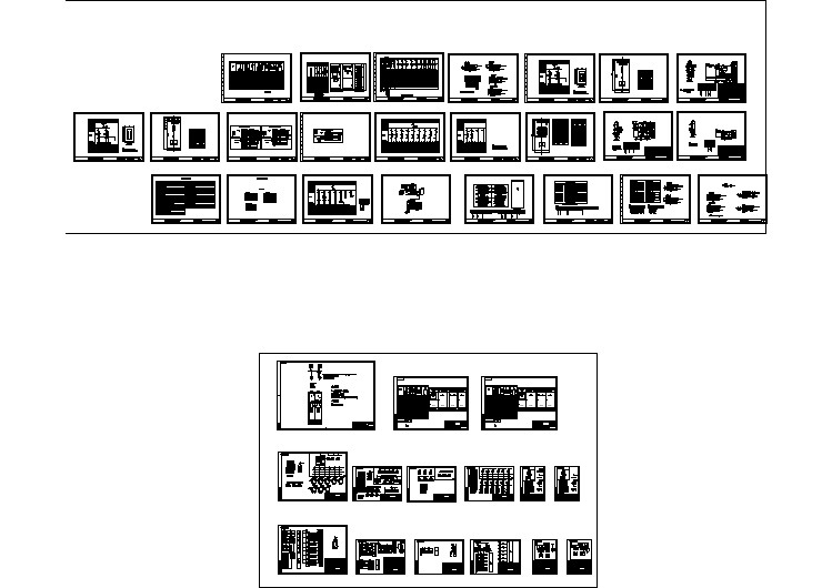
变压器出线柜控制原理图(直流操作)

西门子3AQ型断路器“N2泄漏”故障的定位及处理

西门子3AQ型断路器“N2泄漏”故障的定位及处理邱生苏州供电公司,苏州215004The Orientation and Treatment to The “Loss of nitrogen” Failure of Siemens 3AQ Circuit-BreakerQIU ShengSuzhou Electric Power Company, Suzhou 215128, China摘要:西门子3AQ型断路器在电力系统中有大量采用。
由于采用液压操作机构,“氮气泄漏”是其最常见的故障信号。
为了尽量降低在事故处理中的停电次数以提高供电可靠性,正确的分析及处理故障尤为重要。
文章从物理定位和电气定位两个方面对故障进行分析,给出两个方面的故障处理方法,最后通过三个实际发生的故障实例的处理过程进行了方法验证。
关键词: 3AQ型断路器;故障;物理定位;电气定位Abstract: The 3AQ circuit-breaker is widely used in electric power system. The breaker has a hydraulic operating mechanism, so the signal of “Loss of nitrogen”is the most ordinary failure. In order to raise the power supply reliability, how to correctly analyze and deal with the failure to reduce the outage frequency is very important. This paper analyzes the failure from the electric orientation and physical orientation, gives the treatment methods in above two aspects, finally the treatment methods are verified by three practical fault diagnoses.Key words:the 3AQ circuit-breaker;failure;physical orientation;electric orientation0前言西门子3AQ型断路器是采用SF6气体作为绝缘和灭弧介质的压气式高压断路器,使用固定在断路器本体上的液压操作机构[1]。
三菱工控网
70 N/A 5613 7298
NF630-HEP
300-630 可调
70 N/A 7394 9449
NF800-HEP
400-800 可调
70 N/A 8747 11370
注:RT-热磁可调脱扣器 RE-电子脱扣器
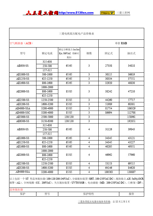
三菱电机低压配电产品价格表
漏电断路器(ELCB)
型号
额定电流(A)
经济型 标准型
NV30-CS NV63-CW NV125-CW NV250-CW NV400-CP NV630-CP NV32-SW NV63-SW NV125-SW NV250-SW
3极
156 320 569 1130 2908 4334 6901 333 350 701 1100 3456 1453 1597 3650 1669
4极
N/A N/A N/A N/A N/A N/A N/A N/A 456 987 1459 4494 1891 2077 4744 2179
三菱各类低压电器市场参考价格,总 12 页之第 4 页
535
3363
3363
4170
报价 56400 10860
220 2630 1620 3480 434 7280 4040CL-T
三菱各类低压电器市场参考价格,总 12 页之第 3 页
1,180 1,180
SBC(短接 b 接点) HP(提升吊钩)
CL-D
45 2409 3441 4473 45 N/A 5243 6814
NF630-SP NF630-SEP NF800-SEP NF1000-SS NF1250-SS
500.600.630. 300-630 可调 400-800 可调 500-1000 可调 600-1250 可调
某大型的泵站高低压及自动参考图
德力西电气 CDB9小型断路器产品样本2019年第5版 产品说明书

产品简介概述产品简介概述系列介绍德力西电气生产的低压断路器产品在国内具有广泛的影响CDB9系列低压终端电气产品,代表了当今国内低压终端配电的最高水平CDB9系列低压终端电气产品,可以广泛应用于工业,民用住宅,商业建筑等领域,对所在电路进行短路保护,过载保护,漏电保护;同时还能起到隔离及控制作用产品外观介绍左视图绿色;表示触头断开 状态位置红色:表示触头闭合 安装孔,用于安装 电气附件正视图右视图热塑外壳强抗冲击性 可回收 有弹性 自熄性 脱扣曲线和额定电流 分断能力和限流等级触头位置状态手柄指示"I-ON"表示触头闭合状态位置 "O-OFF"表示触头断开状态位置 紧固螺钉安装孔,用于 安装漏电模块 安装孔,用于 安装漏电模块拔线指示拔线指示顶视图工作频率额定电压符合标准认证标志12In±20%产品简介产品简介额定电流 1,2,4,6,10,16,20,25,32,40,50,63A 额定工作电压 230/400V AC 极数 1/2/3/4P 最大工作电压 440 V AC 分断能力 6 kA / 10kA 冲击耐受电压 4 kV 限流等级 3隔离功能 切实分断指示快速闭合 保证冲击性负载的可靠工作,延长断路器的电气寿命机械寿命 20000次 电气寿命 10000次环境: 使用环境温度: -30°C 至 +70°C抗湿热性: 2类 (温度55°C 时,相对湿度95%)参考重量 (克)重量121242363484接线 隧道式接线端子可采用上进线下出线方式或下进线上出线方式且无需降容 端子接线面积2及以下导线安装 模块化结构,可方便地安装在DIN 标准导轨上 可垂直、水平或背部安装,特性不受影响 额定扭矩 附件 OF 辅助触头,SD 报警触头,MX+OF 分励脱扣器,过、欠压脱扣器符合标准 IEC/EN 60898-1,GB10963.1 符合认证 CCC 、KEMA 、CE 、CB 、RoSH脱扣特性B 型曲线保护短路电流较小的负载(如电源、长电缆等)脱扣特性: 瞬时脱扣范围 (3~5) In C 型曲线保护常规负载和配电线缆脱扣特性: 瞬时脱扣范围 (5~10) In D 型曲线保护起动电流大的冲击性负荷脱扣特性: 瞬时脱扣范围 (10~14) In短路保护过载保护 控制隔离CDB9断路器适用于工业、民用建筑、能源及基础设施等领域低压终端配电。
深海电子控制有限公司541保护扩展 报警器模块说明书

D E E P S E A E L E C T R O N I C S P L C541P r o t ec ti o n E x p a n s i o n/ A n n u nc i a t o rThe Model 541 Protection Expansion/Annunciator is designed to be used as either a protection expansion module, an annunciator, or a combination of both. The inputs are fully configurable by the user to suit the application. The module features a number of facilities enabling it to be used as a stand alone module or part of a complex control system. It is particularly suited to providing input expansion to the DSE 500 series control modules.The Safety On timer can be selected to be either internal from the Fuel On input being active, or externally fed from another device such as the 520 Automatic Start module.An A larm Reset input is provided to enable the alarms to be cleared. This can be configured to be fed from either plant negative or plant positive DC. This gives maximum flexibility to the module, and allows for interfacing with an output relay on a 520 to enable the 520 module control switch to be the master alarm clear control.The module also features plant DC supply monitoring alarms and can provide indication of a high or low supply voltage. This feature can be disabled if not required.Alterations to the system are made by using a PC and the 808 interface. This also provides the operator with real time diagnostic facilities to monitor the operation of the system.Relay outputs are provided for by way of six configurable outputs. Normally, four relays are configured as Warning, Shutdown, Electrical Trip and Common Alarm outputs. The remaining two relays are configured to signal starting and delayed alarms active. However the relay functions are configurable to activate on a range of functions, conditions or alarms. Outputs of relays 1&2 are at negative plant supply to give compatibility with the inputs to other 500 series modules. Relays 3 to 6 are volt free.The module can be fitted to the 157 relay expansion module to provide a further eight fully configurable volt free relay outputs.Configurable inputs are available for Fuel, Safety on, Reset and Lamp test. This allows the module to function with normally open or normally closed switches. Additionally ten fully configurable auxiliary inputs are provided to give protection expansion or annunciation. These can be selected to be indication, warning, shutdown or electrical trip inputs either immediate, on start-up or held off during safety on delay.Uncommitted LED’s allow annunciation with configurable colour selection – each LED provides choice of Red, Green or Amber. Standard indication or warnings are displayed as ’steady’ illuminations, and Shutdowns or Electrical Trips are displayed as ‘flashing’.The 500 series modules have been designed for front panel mounting . The module is fitted into the cut-out with the fixing clips removed. These are then fitted from the rear. Connection is via locking plug and socket connectors.D E S C R I P T I O N S P E C I F I C A T I O NDC Supply:8 to 35 V Continuous.Cranking Dropouts:Able to survive 0 V for 50 mS, providing supply was at least 10 V before dropout and supply recovers to 5V. This is achieved without the need for internal batteries.Max. Operating Current:340 mA at 12 V. 240 mA at 24 V.Max. Standby Current:15 mA at 12 V. 15 mA at 24 V.DC Alarm Voltage Range: Minimum Low Volts trip 0V Maximum High Volts trip 40V Time delay 0sec – 60minutesAuxiliary Relay Outputs: 5 Amp DC at supply voltage.Dimensions:72 x144 x 118.5mmWeight: 0.5KgOperating Temperature Range: -25 to +55°CIssue 3 VH 13/11/01C A S ED I ME N S I O N ST Y P I C A L C O N N E C T I O N SD e e p S e aE l e c t r o n i c s p l cHighfield House, Hunmanby Industrial Estate, North Yorkshire, YO14 0PH, England Tel:+44(0)1723890099Fax:+44(0)************************************144.0mm7.5mm=Reset Input configurable to be switched to +Ve Plant DC or。
热电保护开关

/item.htm?spm=a230r.1.14.94.0hdxJx&id=17088545870 /item.htm?id=24901432472&ali_refid=a3_420434_1006:1105532664:6:ABB%CB%DC%BF%C7:31597dcb7811cb64 /item.htm?spm=a230r.1.14.287.0hdxJx&id=15084347749 /item.htm?spm=2013.1.w31-18411579990.4.ZM5nMq&id=20553228354 /item.htm?spm=2013.1.0.118.cq8vzb&scm=1007.77.4.0&id=13028285022&pvid=f1fc40e2-b55d-4871-a0f4-7 /item.htm?spm=a230r.1.14.104.bhvnaT&id=23990772492&_u=g1ij920n1001 /item.htm?spm=2013.1.0.118.1hW3wb&scm=1007.77.3.0&id=13911252655&pvid=d25b02da-73d4-43d9-8e4e-a /item.htm?spm=a230r.1.14.111.bhvnaT&id=17910813625&_u=g1ij920n559f /item.htm?spm=a230r.1.14.10.bhvnaT&id=13911288520&_u=g1ij920nb26c /item.htm?spm=2013.1.0.122.vVOsQ5&scm=1007.77.4.0&id=13309011663&pvid=565084af-5b18-45cf-86f9-0
- 1、下载文档前请自行甄别文档内容的完整性,平台不提供额外的编辑、内容补充、找答案等附加服务。
- 2、"仅部分预览"的文档,不可在线预览部分如存在完整性等问题,可反馈申请退款(可完整预览的文档不适用该条件!)。
- 3、如文档侵犯您的权益,请联系客服反馈,我们会尽快为您处理(人工客服工作时间:9:00-18:30)。
IN terminal current
Between IN-GND
Between VR-IN (Note 1)
ISC
SC terminal current
Pd
Power dissipation
Topr
Operating temperature
Tstg
Storage temperature
8
mA
250
VR and VI is maximum, and output OS is high-level, it is considered as a good one. Note 3: When standard value of voltage VSC “ON” is minimum, and output OS is low-level, or when standard value of voltage VSC “ON” is maximum, and output OS
is high-level, it is considered as a good one. Note 4: Supply current 2 is necessary to keep high in output OS. Note 5: After applying 30mV between VR and VI and shorting between them, it is considered as a good one if standard value of IGT flows out of output OS. Note 6: After supply voltage applies 12V and output OS is high-level, it is considered as a good one in the standard value of supply voltage and in the low-level
as 100V and 200V. q High mounting density by SIL package with 8 pins q Wide temperature range (Ta = -20 – +80°C)
APPLICATION
High speed earth leakage circuit breaker
Limits Unit
Min. Typ. Max.
12
V
1
µF
1
µF
ELECTRICAL CHARACTERISTICS (Ta = -20 – 80°C unless otherwise noted)
Symbol
Parameter
Test conditions
Tempera- Test ture (°C) circuit
LATCH
Output OS ← 7
VS
8
REG
Outline 8P5
BLOCK DIAGRAM
VS 8
AMP
7 OS output
Reference voltage generator Latch circuit
GND 3
1
VR Reference
voltage
2
IN Input
4
OD Differential amplifier
PIN CONFIGURATION (TOP VIEW)
Reference voltage VR → 1
Input IN → 2
GND
3 AMP
Differential amplifier output OD ← 4
Latch input SC → 5 Terminal for noise absorption NR → 6
VSC “ON” ISC “ON” IOSL VIC
SC “ON” voltage (Note 3) SC input current Output low-level current Input clamp voltage
IS1 = 580µA
-20
5
VSC = 1.4V VOS = 0.8V
IS1 = 530µA
Limits Min. Typ.∗ Max.
Unit
-20
1
580
IS1
Supply current
VS = 12V, VR-VI = 30mV
25
1
80
1
400 530 µA 480
VT
Trip voltage
VS = 16V, VR-VI (Note 2)
-20 – +80
2
4
6.1
9
mVrms
Latch circuit is off-state supply voltage (Note 6)
25
13
0.5
V
TON
Operating time (Note 7)
VS = 16V, VR-VI = 0.3V
25
14
2பைடு நூலகம்
4
ms
Note ∗: Typical values are at Ta = 25°C. Note 2: When standard value of voltage (60Hz) between VR and VI is minimum, and output OS is low-level, or when standard value of voltage (60Hz) between
FEATURES
q Suitable for JIS C 8371 q Good temperature characteristics of input sensitivity current q High input sensitivity (VT = 6.1mV Typ.) q Low external component count q High noise and surge-proof q Low power dissipation (Pd = 5mW Typ.) and may be used both
MITSUBISHI <CONTROL / DRIVER IC>
M54123L
EARTH LEAKAGE CURRENT DETECTOR
BIAS
DESCRIPTION
The M54123L is a semiconductor integrated circuit with amplifier for a high-speed earth leakage circuit breaker.
Symbol
Parameter
Conditions
Ratings
Unit
IS
Supply current
Between VR-IN (Note 1)
IVR
VR pin current
Between VR-GND
Between IN-VR (Note 1)
Between IN-VR (Note 1)
IIN
Remarks: GND terminal (pin 3 ) of the circuit is a basis of all the voltages except differential input clamp voltage of DC electrical characteristics, and direction of current is plus (no signal) in flowing into the circuit and is minus (–signal) in flowing out of it. Maximum value and minimum one are shown as absolute value. Please don’t apply voltage whose standard is GND terminal in VR and IN pin.
ITD1
Timed current 1
VS = 16V, VR-VI = 30mV, VOD = 1.2V
25
3
-12
-30
µA
ITD2
Timed current 2
VS = 16V, short circuit between VR and VI, VOD = 0.8V
25
4
17
37
µA
IO
Output current
RECOMMENDED OPERATING CONDITIONS (Ta = -20 – 80°C unless otherwise noted)
Symbol
VS CVS COS
Parameter
Supply voltage when latch circuit is off-state External capacitor between VS and GND External capacitor between OS and GND
25
5
IS1 = 480µA
80
5
VS = 16V
25
6
VS = 12V
25
7
VS = 12V, VOSL = 0.2V
-20 – +80
8
VS = 12V, IIC = 20mA
-20 – +80
9
-200 -100 -75 0.7
200 4.3
µA
1.4
V
5
µA
µA
6.7
V
VIDC
Differential input clamp voltage