lei2000系列变频器说明书
L2000射频导纳物位控制器说明书
选型举例:L2000 - 220VAC / L843 - 150mm - 450mm 上例表示:L2000型射频导纳控制器,供电电源220VAC,为标准探头,探头总长450mm, 保护套长150mm
灵敏度细调
灵敏度粗调
输出状 态指示
杆式标准探头L843
杆式防腐探头L843TS 注:防腐探头必须用法兰安装,法兰尺寸由用户自选,默认标准为DN15PN1.6。 杆式飞灰探头L853
杆式高温探头L864
注: 杆式高温陶瓷探头必须用法兰安装,石棉板隔热密封,法兰尺寸由用户自选, 默认标准为DN15PN1.6。 3
缆式探头L843W
缆式防腐探头L843TW
美国RRINCO公司物位控制器是真正的射频导纳物位控制 器。
仪表特点:
■通用性强: 可应用于各种导电和非导电介质的测量,例如液 体、粘稠物、颗粒、粉末、飞灰。
■可抗粘附: 采用专利的抗粘附电路,可以消除因物料粘附而产 生的虚假信号。
■探头可拆: 控制器与探头之间没有电缆连接,随时可以将控制 器拆除更换维修,不影响进出物料。
或5A,220VAC 延时时间: 0-30秒可调:(开或关) 电源电压: 120/240VAC, 50/60HZ或24VDC 功 率: 3W 外壳标准: 铸铝,标准 环境温度: -40℃~+66℃ 灵 敏 度: 0.5pf~750pf 防 爆: I级,C或D组;II级,E,F或G组。 失电保护: 常开或常闭,现场可切换。 电气接口: 3/4" NPT
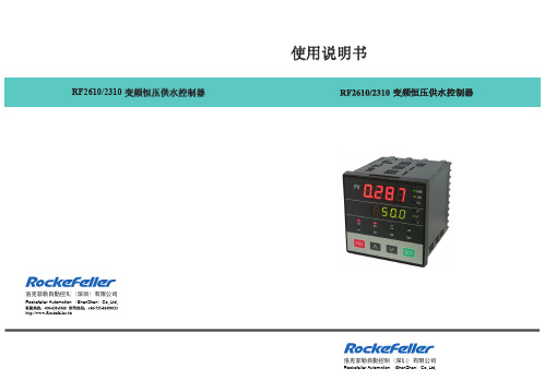
220vac24vdc灵敏度细调灵敏度细调灵敏度粗调灵敏度粗调输出状态指示输出状态指示高低位报警选择高低位报警选择输出延时指示输出延时指示24vdc控制器外壳尺寸探头尺寸单位mm
2000型操作手册

如有其它问题请资询经销商或生产厂家
第五部分:给水控制器使用说明书-TW2000
键盘操作说明:
(注:该使用说明适用于一带一及一用一补(备)等机型)
黑龙江斯福电气有限公司
技术支持电话:0451-82666766
斯福变频给水控制柜操作指南目录
一、 二、 三、 四、 五、 六、
功能简介 柜体各器件名称简介 快速操作指南 常见故障及处理 2000 型控制器说明书 随机技术性文件
斯福给水控制柜功能简介
以设定压力,给厂家及用户都带来了极大的方便 z 具有小流量停机功能(即休眠功能),在节能方
面有特殊要求的场合能给您带来方便。 z 设定压力和实际压力为三位数码显示,所以提高
了对 1.6Mpa,2.5Mpa 远传压力表的显示精度及控 制精度。在高层供水及特殊场合,能给您带来方 便。 z 电源为开关电源和线性电源两种,开关电源抗干扰能力特别强,电压范围 宽,特别适用农村电网。 z 报警齐全,具有变频器故障,远传表断线及短路故障或欠压超时和水位报 警指示。 z 密码控制定时停机,在特殊问题的处理上能给您带来方便。 z 可编程三段时控起停(三起三停),分时段变压(六段压力值)(T 选项) z 箱体采用静电喷涂工艺,无眩光,防腐能力强 z 面板指示灯一应俱全,操作简单 z 可选落地式柜体和壁挂式箱体
该图为落地式柜体
第二部分:柜体各器件名称简介
柜体由以下主要器件组成:
2-1:面板器件布置及名称:
1、 显示仪表(壁挂式柜体无此配件,可选) 2、 给水控制器(简易型无此配件) 3、 转换开关 4、 带灯按钮 5、 指示灯 6、 门锁
RF2000说明书
3 控制器的接线……………………………………………………4 3.1 接线图……………………………………………………………………………4 3.2 实物端子排布图…………………………………………………………………4 … 3.3 控制器的端子接线说明…………………………………………………………5
16 VRC 控制器模拟电压输出,控制变 频器频率 VRCMAX=5V 或 10V
17 GND
18 EMG 接变频器的滑行停止控制端
19 RUN 接变频器的运行控制端
20 CM 公共端(端子 18,19 使用)
端子名称 说
明
21 B4 4 号泵变频泵控制接点
22 D4 4 号泵工频泵控制接点
23 B5 5 号泵变频泵控制接点
S1 36
第二压力/消防巡检
GND 37
信号公共端
485A 38
RS-485通迅 + 端
485B 39
RS-485通迅 - 端
3.2 实物端子排布图
1
21
31
11
1
AC 220V
B4 21
31 R/S 11 +5V
2
22
32
12
2
D4 22
32 GND 12 PI
3
23
33
13
COM 3
B5 23
33 ALM 13 GND
Rockefeller Automation (ShenZhen)Co.,Ltd.
目录
1 前言……………………………………………………………1 1.1 主要功能特点……………………………………………………………………1 1.2 技术指标…………………………………………………………………………2
电子论文-华蓝科技HL2000系列变频器使用手册
变频器型号规格 电缆线截面积(mm) 变频器型号规格 电缆线截面积(mm)
HL2000-00D5-TD 1.5
HL2000-11D0-T 10
HL2000-00D7-TD 2.5
HL2000-15D0-T 10
本手册仅用于学习,请勿用于其它非法途径!不经同意请勿转载!
编者:敖卫兵
邮箱:aoweibing9908@
危险
12..
确认端子外罩安装好了之后,方可闭合输入电源,通电中,请勿拆卸外罩。有触电的危险。 若变频器设定了停电再启动功能,请勿靠近机械设备,因来电时变频器会突然再启动。有受伤的危险。
3. 请接入紧急停止开关(停止键盘运行设定时有效)。有受伤的危险。
注意
1. 制动电阻两端的高压放电会使温度升高,请勿触摸制动电阻。有触电和烧伤的危险。
23..
运行前,请再一次确认电机及机械的使用允许范围等事项,有受伤的危险。 运行中,请勿检查信号。会损坏设备。
4. 请勿随意改变变频器的设定。该系列变频器在出厂时已进行了适当的设定,会引起设备的损坏。
●保养、检查
危险
1. 请勿触摸变频器的接线端子,端子有高电压。有触电的危险。
23..
通电前,请务必安装好端子外罩,拆卸外罩时,一定要断开电源。 切断主回路电源,确认 CHARGE 发光二极管熄灭后,方可进行保养、检查。电解电容上有残余电压
邮箱:aoweibing9908@
端子功能说明 当STPST端R断与开C,OM当断ST开R时与,C电O机M停闭止合;时ST,P电端机闭正合转时启,动ST;P 一与下CO立M即闭闭合合一,下电立机即停松止开运,行电机正转启动;STP 端断开 当STPST端R断与开C,OM当断ST开R时与,C电O机M停闭止合;时ST,P电端机闭反合转时启,动ST;P 一与下CO立M即闭闭合合一,下电立机即停松止开运,行电机反转启动;STP 端断开 电当机ST停P止端运断行开,电机启动;只要启动 STR 一下马上闭合, JOG 与 COM 闭合时,断开电机停止 当 EXT 与 COM 闭合时,变频器显示外部故障报警代码, 同时电机将停止运行。 故障时 RST 与 COM 闭合系统复位 出厂设定为第一步(详见参“32-35”)
变频器说明书大全
红邦控制技术4.ABB变频器说明书ACS400ACS500ACS5105.AB变频器说明书1336PLUS II PowerFlex 4PowerFlex 406.AC Tech变频器说明书MC1000QC SCF7.BERGES变频器说明书ACM-D2/S2/S3ACM-COMPACT8.BONFIGLIOLI邦飞利变频器说明书ACT200/400ACU200/400VCB4009.CT变频器说明书Command er GP Unidrive SP Command er SE 10.Drivecon变频器说明书XS XT XR 11.EATON伊顿变频器说明书SVX9000SPX9000MVX900012.KEB科比变频器说明书F4-S F4-F F5-M 13.LG变频器说明书iS3iH3iG514、LUST路斯特变频器说明书CDD3000CDE/CDB3000CDS400015.Moeller金钟-默勒变频器说明书DV6-340DF5116.NORD诺德变频器说明书SK300ESK400ESK5xxE17.PDRIVE变频器说明书18.PE变频器说明书SD100SD250SD45019.RICH利佳/艾瑞克变频器说明书EI-MINIEI-450EI-450M20.SEW变频器说明书MOVITRAC -31C MOVIDRIV E-60B/61B MOVITRAC -0721.SIEI西威变频器说明书ARTDriveL ARTDriveG-EV22.TMT变频器说明书PLUS VTC E 23.VACON瓦控变频器说明书NX NXS NXL 24.WEG变频器说明书CTW-04CFW-08CFW-0925.阿尔法ALPHA变频器说明书ALPHA2000G ALPHA2800ALPHA330026.艾默生(原华为)变频器说明书EV1000EV2000EV300027.爱得利变频器说明书APXG3ASASN28.爱迪生Adsen变频器说明书ADS-A29.安邦信AMBITION变频器说明书G9/P9V11G1130.安川YASKAWA变频器说明书G5G7E731.安普(AMPLE)变频器说明书AMP100032.百德福BEDFORD变频器说明书B500B80133.斑科Bantek变频器说明书BLDC34.宝德电气BODE变频器说明书BEM100BEM20035.葆德BALDOR变频器说明书10111236.贝西B&C变频器说明书BC-1000BC-2000BC-2300MX-eco/pro/multi-eco/multi-pro-1MX-eco/pro/m eco/multi-pro-237.传动之星(STAR@DRIVE)变频器说明书SD-5L-G/P/YSD-5L-S SD-7L38.创杰变频器说明书ACT-V6G/P/ZACT-M739.春日(KASUGA)变频器说明书KVFC40.丹佛斯(Danfoss)变频器说明书FC51FC100FC20041.德弗(DOVOL)变频器说明书DV300DV600ST50042.德莱尔变频器说明书DVA DVM DVS43.德力西变频器说明书CDI900044.德瑞斯(DIRISE)变频器说明书DRS1000-M DRS2000DRS280045.东达变频器说明书TDS-F8TDS-V846.东洋(TOYO)变频器说明书VF61R VF6447.东元(TECO)变频器/伺服说明书7300EV7300CV7200MA48.东芝(TOSHIBA)变频器说明书VF-nC1VF-S9VF-S1149.方禾(FangH)变频器说明书TE280F66-B F66-C50.飞兆变频器说明书FG51.佛朗克(FRANCK)变频器说明书FRS2000FRB600052.佛斯特(FIRST)变频器说明书FST-500FST-550FST-60053.富凌(FULING)变频器说明书DZB60J DZB70B DZB200M54.富士(FUJI)变频器说明书FRN-G11S FRN-P11S E1S55.高士达(GOLDSTAR)变频器GS200L56.哥伦(GRET)变频器说明书GD-V557.格立特(GREAT)变频器说明书VF10VF11VF1558.海利普变频器说明书HOLIP-A/F/H/MHOLIP-C HOLIP-P59合康亿盛高压变频器说明书HIVERT通用HIVERT矢量60.泓筌变频器说明书HC1-A HC1-M61.鸿宝(HOSSONI)变频器说明书HB-G9/P9HB280-G HB280-P62.华科(HUANIC)变频器说明书HI3G/F HI9G/F63.华蓝(HLinverter)变频器说明书HL200064.汇川(INOVANCE)(默纳克NICE)变频器说明书MD300MD300A MD32065.汇菱(HUILING)变频器说明书H300066.基创变频器说明书E35067.吉纳变频器说明书MSC-3MFI-Case00/CaseA/CaseB68.加能变频器说明书ACmaster-H7IPC-MD IPC-DR69.佳川(JiaChuan)变频器说明书BP60JCRQ70.佳灵变频器说明书JB6C-T971.金肯(JINKEN)变频器说明书JK-G/P72.九德松益变频器说明书CT-200073.开拓变频器说明书KT-A6G/P74.凯迪华能变频器说明书CD200075.康沃(博世力士乐)变频器说明书S1G2G376.科陆变频器说明书CL1700CL2700CL370077.科姆龙变频器说明书KV1900KV200078.库马克变频器说明书CMK-30079.酷马(QMA)变频器说明书Q7000Q900080.乐邦变频器说明书LB60G LB90G81.乐星产电变频器说明书Starvert82.雷诺尔变频器说明书JJR1000JJR2000JJR500083.力普变频器说明书LP10084.菱科(LINGKE)变频器说明书LK600-G/P/ZSLK80085.隆兴变频器说明书LS200A LS600LS80086.路斯特(LUST)驱动器说明书AD系列CDD系列87.伦茨(Lenze)变频器说明书8200/82108220/8240823088.麦孚变频器说明书VFD-F540VCD100089.麦格米特变频器说明书MV300MV60090.美之源(MZY)变频器说明书MZY-M/Y/Z/T/L91.蒙德(MODROL)变频器说明书IMS-GF IMS-GL2IMS-GL392.米高变频器说明书Micovert2003Micovert34 0N93.明电舍(MEIDEN)变频器说明书VT230S VT230SE VT240S94.南方安华变频器说明书A100E100S10095.能士(NSA)变频器说明书NSA20NSA8096.宁茂(赫力)变频器说明书RM597.欧陆变频器/直流调速器说明书512C590+590P98.欧姆龙(OMRON)变频器说明书3G3JV3G3EV3G3FV99.欧瑞(HFinverter)(原惠丰)变频器说明书F2000-G F3000F1000-G100.派克汉尼汾(parker)变频器说明书AC650AC650V AC690+ 101.派尼尔(Pioneer)变频器说明书VF2100VF3000VF5000 102.普传(POWTRAN)变频器说明书PI97G PI7000/7100PI7500103.群倍(QUNBEI)变频器说明书QLP5000104.日搏变频器说明书RB600RB3000RB5000 105.日锋(RiFeng)变频器说明书RF200RF9000106.日虹变频器说明书CHRH-A CHRH-C CHRH-D 107.日立(HITACHI)变频器说明书SJ100L100SJ200 108.日普(RIPOW)变频器说明书RP3200109.日拓变频器说明书HL3000110.日业(SUNYE)变频器说明书SY3200111.荣信电力电子变频器说明书HVC112.瑞恩(RELIANCE)变频器说明书PSC4000/5000/DDS5000PSC7000VZ3000113.赛普(SAPPHIRE)变频器说明书SAP500G SAP300114.赛普变频器说明书SAP900G SAP300V115.三晶变频器说明书SAJ8000116.三肯(SANKEN)变频器说明书SAMCO-i SAMCO-vm05SAMCO-e117.三菱(MITSUBISHI)变频器说明书A500E500F500 118.三木(MIKI)变频器说明书V6119.三品(SANPIN)变频器说明书SKJ SPRQ-333120.三碁(SANCH)(三川)变频器说明书SA SE121.三星(SAMSUNG)变频器说明书MOSCON-E7MOSCON-F7MOSCON-F500122.森兰(SENLAN)变频器说明书SB50SB60/61SB61Z 123.山宇变频器说明书SY6000SJR2124.珊星变频器说明书F5000F6000125.深川变频器说明书SVF2000SVF3000126.神源(SYRUNS)变频器说明书SY4000SY5000127.施耐德变频器说明书ATV38ATV58-1ATV58-2 128.时代变频器说明书TVF1000TVF3000TVF5000 129.时运捷变频器说明书SuperBona-iF/iPDB-2100130.士林变频器说明书SH系列SS系列SB系列131.世通(EACON)变频器说明书EC1000EC3000EC5000 132.收获(Seoho)变频器说明书SOHO-VD SOHO-SMS133.思达(SD)变频器说明书JPSD3000-G/P/V/H134.斯德博(STOBER)变频器说明书FAS4000FDS4000MDS5000 135.四方变频器说明书C300C320E320 136.松下(PANASONIC)变频器说明书VF0VF0C VF-8Z 137.台安(TAIAN)变频器说明书E2N2V2138.台达(DELTA)变频器说明书VFD-A VFD-B VFD-F 139.台凌(TAILING)变频器说明书TL80TL100TL100H 140.腾龙变频器说明书VG3000-G/H141.天正变频器说明书TVFS9TVFG9/P9TVFG11 142.万谷(WANGU)变频器说明书VF2000143.威尔凯变频器说明书WKF WKS WKR5000 144.威科达变频器说明书V6145.威灵(WELLING)变频器说明书WELLING-G/P/F146.微能变频器说明书WIN-VB WIN-9G WIN-9F 147.韦尔变频器说明书AC30G/P/W/H148.伟创(VEICH)变频器说明书AC20AC32AC60 149.沃森(VicRuns)变频器说明书VSI9000150.西驰变频器说明书CFC1000CFC4000151.西尔康变频器说明书H3000152.西林变频器说明书EH600A EH600M EH600W 153.西门子(SIEMENS)变频器说明书MM410MM420MM430154.现代(HYUNDAI)变频器说明书N50N100N300 155.晓磊(CHXL)变频器说明书LEI2000LEI2005LEI3000 156.信捷(XINJE)变频器说明书V5/F5157.星河(XINHE)变频器说明书SD-5L158.亚泰(YT)变频器说明书YTD-G160.阳冈电子变频器说明书G1/H1/P1E1S1 161.依尔通(Emotron)变频器说明书FDU VFX VSA 162.依托(ESTAR)变频器说明书EG/EF163.亿森变频器说明书参数表164.易能变频器说明书EDS700EDS2860165.易驱变频器说明书ED2003ED2800ED3000 166.意科(IECCO)变频器说明书SINUS-N167.英泰(Invertek DRIVES)变频器说明书OptidrivePlus 3GV OptidrivePlus3GVCompactOptidriveVTC168.英威腾(INVT)变频器说明书CHV100CHV190CHF100 169.鹰垦(INK)变频器说明书SLX170.优利康变频器说明书YD3000YD5000171.尤尼康(UNICON)(原北京兰海)变频器说明书低速大扭矩无码盘有码盘172.誉强(YUQIANG)变频器说明书YQ3000-M YQ3000-A YQ3000-G 173.远川(YCDZ)变频器说明书YC-G YC-P174.正频(JPS)变频器说明书PDS PDA/H/E175.正泰(CHINT)变频器说明书NI01176.正弦(SINEE)变频器说明书SINE300SINE303SINE307 177.正阳(Zhengyang)变频器说明书ZY29/31/98ZY-812178.中源(ZYDL)变频器说明书ZY-G800ZY-G800E ZY-A900 179.中远变频器说明书MF6MF5/20MF30 180.珠峰变频器说明书DLT-G11/P11/Z181.住友(SUMITOMO)变频器说明书HF320SF320HF430 182.紫日(CHZIRI)变频器说明书ZVF7ZVF9ZVF9V 183.南海华腾(V-T)变频器说明书V5-H E5-P V6-HACS600ACS800ACS1000PowerFlex 400PowerFlex 70PowerFlex 700SE1SW1SYN10S/T SPL200/400VF5100HG VF51RG VFDBVF61CVF61VF64VFK1/VFN 1GVX9000F5-M/S iS5iHSK530E SK700E SK750ESD700EI-500EI-550EI-600EI-700EI-7001EI-8001EI Super NMOVIRET-315/328/355/380/3150IP55 PLUS IP55 E CFW-10CFW-11EV3100EV3500TD900TD1000TD2000TD3000TD3100MSE11Z9/Z11F7J7V7PC3P5/PC514ro/multi-co/multi-pro-2FC300VLT2000VLT2800VLT2900VLT3000VLT5000 HL2000DV1000DRS30007200GA7300PA7200GSVF-A5VF-A7VF-AS1DZB300BF1S FRN-FVR-E11SMini/C1SHB280-ZMD330ME280NICE3000IPC-RF9300Vector690+590C3G3HV3G3MV3G3RVF1500-GPI7600/78PI766000SJ300SJ300-EL L200L300P VZ7000MF/MS ES/ET/EF IHF/IPF SHF/SPFS500A700E700F700D700 SB70SB100SB200BT40ATV61ATV68-1ATV68-2ATV68-3SDS4000E350E380E520H320M1X M2XVF100DV700/707SV300N310S310EV300VFD-G VFD-M VFD-S VFD-VWIN-9I WIN-9LAC61-Z AC62-LEH600ZMM4406RA706SE70J300TOPVERT TOPVERT TOPVERTVSC CDX CDU MSF ED300S ED3100Optidrive E OptidriveE1OptidriveE2OptidriveMEMA 4XSINE308SINE309 ZY-P800ZVF11VFN2TD3200TD3300。
江苏力普LP-A2000变频器调试说明

江苏力普LP-A2000变频器简单调试
说明:之前在网上找江苏力普LP-A2000变频器电子版说明书,没有找到,之后找到一本江苏力普LP-A2000变频器说明书,经过整理,将资料传至网络,希望能帮到像我一样需要变频器说明书朋友,此文档不是变频器说明书的全部内容,但是基本包含了变频器调试时所需的信息。
一、变频器运行配线图及端子说明
二、BOP面板操作
【图】BOP面板按键说明
【图】BOP面板按键说明
【图】BOP面板状态指示灯说明
【图】变频器状态参数显示切换
【图】变频器状态参数代码说明
三、变频器参数
四、故障代码
21 / 21。
SSI RI2000说明书

P R E L I M I N A R YO P E R A T I O N A N D S E R V I C E M A N U A LF O R T H ER E F R A C T I V E I N D E X D E T E C T O RR I2000Schambeck SFD GmbHRhöndorfer Strasse 51 · D – 53604 Bad Honnef, Germany Telephone: +49 (0) 2224 9239 0 · Telefax: +49 (0) 2224 9239 20Version 2.0 (FirmWare V4.0)Printed: 13/12/2005 File: RI2000 english.docLast modified: BJOERNT ABLE OF C ONTENTSTABLE OF CONTENTS 1 1CONTACT ADDRESS 4 2PRECAUTION AND WARNINGS 5 3ELECTRICAL WARNINGS 5 4GENERAL WARNINGS 6 5SPECIFICATIONS 8 6PHYSICAL SPECIFICATIONS 9 7GUARANTEE CONDITIONS 10 8PARTS INCLUDED IN THE DELIVERY 11 9FRONT PANEL AND KEYBOARD 12 9.1T HE DISPLAY12 9.2T HE A UTO Z ERO B UTTON 13 9.3T HE P URGE B UTTON 13 9.4T HE B UTTON P OL +/- 13 9.5T HE B UTTONS A RROW L EFT (◄) AND A RROW R IGHT (►) 13 9.6T HE B UTTONS A RROW U P (▲) AND A RROW D OWN (▼) 13 9.7T HE M ENU B UTTON 14 9.8T HE E NTER B UTTON 14 9.9T HE IN PORT14 9.10T HE OUT PORT 14 10THE BACK SIDE OF THE RI2000 15 10.1O UTPUT-C ONNECTORS 15 10.1.1T HE I NTEGRATOR S IGNAL O UTPUT 15 10.1.2T HE R ECORDER S IGNAL O UTPUT 15 10.1.3T HE D IGITAL O UTPUT 15 10.2I NPUT-C ONNECTORS 16 10.2.1T HE E XTERNAL S TART S IGNAL 16 10.2.2T HE E XTERNAL A UTO Z ERO S IGNAL 16 10.2.3T HE E XTERNAL P URGE S IGNAL 16 10.3T HE RS232P ORT 16 10.4M ASS S CREW 17 10.5O PTICAL A DJUST 17 10.6D RAIN1710.7M AINS A DAPTOR 17 10.8F USES1711INSTALLATION OF THE RI2000 1811.1C ONNECTING THE DETECTOR TO THE CHROMATOGRAPHY SYSTEM 18 11.2C ONNECTION TO AN A NALOG D ATA S YSTEM 19 11.3C ONNECTION TO A D IGITAL D ATA S YSTEM (PC) 1912PRINCIPLE OF DETECTION 2012.1T HE O PTICAL S YSTEM OF THE RI2000 2013FLOW PATHS IN THE RI2000 2113.1M EASURING M ODE 21 13.2P URGE M ODE 22 14OPERATING THE RI2000 DETECTOR 23 14.1O VERVIEW F IRMWARE V ERSION 3.2C 23 14.2T HE I NITIALIZATION S TAGE 24 14.3T HE N ORMAL M EASURING M ODE (N ORM M ODE) 25 14.4T EMPERATURE S ETTINGS 27 14.5S ETTING S IGNAL S MOOTHING 29 14.6S ETTING R ECORDER R ANGE –S IGNAL A MPLIFICATION 30 14.7S ETTING R ECORDER O FFSET AND R ECORDER E XTENT 31 14.7.1R ECORDER E XTENT 31 14.7.2R ECORDER O FFSET 31 14.8M ARKERS33 14.9S ETTINGS FOR S ERIAL P ORT (RS232) 34 14.10M ENU S TRUCTURE IN N ORMAL M EASURING M ODE (N ORM M ODE) 3515THE SERVICE MODE 3615.1F IRMWARE I NFORMATION 37 15.2V IEW F INE M ODE 38 15.3A DJUSTING D IGITAL –A NALOG –C ONVERTERS 40 15.4C ALIBRATING THE RI2000 41 15.4.1H OW TO CALIBRATE (42)15.5S ERV M ODE O VERVIEW 45 15.6S ERIAL C OMMUNICATION 46 16MAINTENANCE OF THE RI2000 47 16.1I DENTIFYING H ARD- AND S OFTWARE 47 16.2E RROR M ESSAGES 48 16.2.1M ALFUNCTION OF THE T EMPERATURE S ENSOR 48 16.2.2M ALFUNCTION OF THE A NALOG D IGITAL C ONVERTER 49 16.2.3I NTENSITY A LARM 4916.2.4S IGNAL O UT OF R ANGE 50 16.2.5R ESET C ONFIGURATION 51 16.3A DJUSTING THE OPTICAL SYSTEM 53 16.4L AMP E XCHANGE AND A DJUSTMENT OF THE L AMP 55 16.5C HECKING S UM- AND D IFFERENCE V OLTAGES 59 16.6C HECK AND R EPLACEMENT OF THE V ALVE 62 16.7C HECKING AND C LEANING THE F LOW C ELL 64 16.8T HE H EATING C IRCUIT OF THE RI2000 6717VOLTAGE TEST POINTS 6818SPARE PARTS 6919TEST POINTS FOR LAMP VOLTAGE (FOR SERIAL NUMBER 0312XXX) 7020TEST POINTS FOR LAMP VOLTAGE (FOR SERIAL NUMBER 0401XXX) 7121VOLTAGE TEST POINTS (OVERVIEW) FOR 0312XXX SERIES 7222VOLTAGE TEST POINTS (OVERVIEW) FOR 0401XXX SERIES 73DECLARATION OF CONFORMITY 741 C ONTACT A DDRESSIn case of problems with your RI2000 refractive index detector please contact your local distributor or Schambeck SFD GmbH.Schambeck SFD GmbHRhöndorfer Strasse 51D – 53604 Bad HonnefGermanyTelephone: +49 (0) 2224 9239 0Telefax: +49 (0) 2224 9239 20Email: mailto@2 P RECAUTION A ND W ARNINGSThe manufacturer is not reliable for any damage, harm or financial loss caused directly or indirectly by the use of this instrument if the instrument is handled without the observation of this manual or handling with carelessness.■NOTEPlease read this manual carefully before working with the RI2000 refractive index detector. In case of any question please do not hesitate to contact you local distributor or Schambeck SFD GmbH directly.3 E LECTRICAL W ARNINGS•Before opening the housing of the instrument make sure the detector is switched off and disconnected from power supply.•The voltage selected at the fuse on the backside of the instrument has to be set correctly to 110 V or 220 V according to your local power supply.•Before changing the selected voltage the power supply has to be disconnected.• The detector may only be connected to plugs with grounding.•The RI2000 may only be operated in connection with other devices which fit to the safety requirements.4 G ENERAL W ARNINGS•To prevent damages of the RI2000 all capillaries and cables have to be checked for damages and leakages.•For the disposal of inflammable and/or toxic solvents a plan for waste management has to be created. Such solvents may not get into the drain.•The RI2000 refractive index detector is built to operate at temperatures between 10 °C and 35 °C.•To reach a reliable operation of the detector it is recommended to use filtered samples and solvents only.•The detector may be cleaned with appropriate cleaning agents only.•Make sure that no liquid gets inside the detector. Liquid inside the housing may cause electrical short circuits which may result in the damage of the instrument.•To prevent electrical shocks make sure that the detector is disconnected from power supply when the housing is opened to perform service work inside.•To disconnect the instrument from power supply simply unplug the power cable.•Electronic circuit boards and electronic components are sensitive to electrostatical charges.•For some maintenance operation it is required to open the instrument’s housing. Make sure that the instrument is disconnected from power supply before removing the housing. It it is necessary to remove the housing during operation make sure not to touch electrical parts inside the detector.•In case of the use of dangerous solvents pay attention to safety instructions regarding this solvent.•Solvents should be degassed before use with a refractive index detector.•After use of salt containing solvents (such as buffers) the detector should be purged with distilled water.•Make sure that the 6 bar (0.6 MPa) pressure limit of the flow cell is not exceeded.•Make sure that the 2 bar (0.2 MPa) pressure limit of the valve is not exceeded.•During operation the housing of the detector should be closed.•Do not use the detector in ambience of aggressive gases, very high humidity, strong vibrations and strong changes in the ambience’s temperature.5 S PECIFICATIONSType of detection: Refractive IndexEffective range for refractive index: 1.00 – 1.75 RIUEffective range: ± 1000 µRIUOptical null balance: In the whole effective range byadjusting the mirrorSignal null balance: In the whole effective range by usingthe AutoZero functionMaterials which contact the mobile phase: Stainless steel, glass, PTFE Maximum pH-range: 2.3 – 9.5Temperature control for optical bench: 7°C above ambient temperature,35 °C up to 55 °C in 1 °C steps Analog signal output: Recorder / integratorNoise (analog signal): ± 7 nRIU (± 7 µV)Noise (digital output): ± 3 nRIU (± 3 µV)Drift: < 1 µRIU/h (< 1mV/h)Integrator output: ± 1.2 V (fix)Recorder output: ± 1.2 V (adjustable)Recorder range: 8 steps selectable in the region from1/8 to 16/1Recorder offset: Selectable: 0 mV, 10 mV, 100 mV Signal range (recorder): Selectable: 10 mV, 100 mV, 1000 mV Recorder marker: Marker function ON/OFFFlow cell: Glass cell (quartz) with two chambers Volume: 9 µLAngel: 45 °Max. Pressure: 6 bar (0.6 MPa)Max. Flow rate: 0.1 – 3.0 mL/minValve: 3/2 path valve, 12 VMax. Pressure: 2 bar (0.2 MPa)Volumes: Sample entry → sample cell: 24 µLSample entry → sample cell →reference cell → sample exit: 1500 µLinterface: RS232, bidirectional Communication: DigitalDigital input: TTL (Purge, AutoZero,Start/Marker)Digital output: TTL (Intensity alarm)6 P HYSICAL SPECIFICATIONSDimensions: 220 mm * 165 mm * 350 mm (W * H * D)kgWeight: 12Voltages: Mains adaptor with voltage selectorV120–100V240220–Frequency: 50 or 60 HzPower consumption: max. 50 WTemperature range: 10 °C to 50 °C7 G UARANTEE CONDITIONSThe term of guarantee depends on you local law. Beside this Schambeck SFD GmbH affords guarantee for at least 12 months beginning after purchase of the RI2000 refractive index detector.All instruments are tested and certified by Schambeck SFD GmbH quality control. Only defects which result from faulty manufacture or material defects are covered by the guarantee. In case of a defect the original sales slip will be needed to make use of the guarantee. Repair works covered by the guarantee may only be performed by Schambeck SFD GmbH or licensed distributors.The following cases are not covered by the guarantee:•Improper use (e. g. capacity overload, use of not approved tools) of the RI2000 detector•Parts which are liable to aging or abrasion like lamps, valves, heater cartridges or flow cells•Damages caused by use of force or not approved tools• Damages which result from improper use due to non-observance of the operation manual, the use under abnormal conditions or improper maintenance•Defects resulting from the use of third-party parts which are not approved by Schambeck SFD GmbH•Instruments which are modified after purchasing by the customer• Normal abrasion•Fully or partial disassembled refractive index detectors8 P ARTS INCLUDED IN THE DELIVERYQuantity Description1 EA Refractive Index Detector RI20001 EA Stainless steel capillary, 0.25 mm inner diameter, 1.59 mm outerdiameter (for sample entry)1 EA Stainless steel capillary, 1.00 mm inner diameter, 1.59 mm outerdiameter (for sample exit)1 EA PTFE tube, 1.59 mm inner diameter, 2.80 mm outer diameterexit)(forsample2 EA Screw connection (for sample entry and sample exit)cable1 EA Power2 EA Fuses (0.5 A, slow)2 m Signal cable, 2-wired1 EA Hex-wrench (for adjustment of the mirror, ∅ 2.5 mm)1 EA Operation & Service Manual9 F RONT P ANEL AND K EYBOARD9.1 T HE DISPLAYThe RI2000 refractive index detector is equipped with a liquid crystal display to show the current detector signal as well as system parameters. This display contains four lines with 20 characters each.Line 1 shows the current temperature of the optical bench (in °C).Line 2shows the optical balance (in %%).Line 3shows the current detector signal (in mV).The value shown here is identical to the digital output signaland to the analog signal which can be recorded at theoutput.recorderLine 4This line shows the status of the RI2000 detector. Every fewseconds the displayed parameter changes. By this you canget a complete overview of all parameters in a short time.9.2 T HE A UTO Z ERO B UTTONBy pressing the AutoZero button the detector signal is internally set to Zero. To return to the formel (unmodified) signal, press the AutoZero button for approx. three seconds.9.3 T HE P URGE B UTTONTo flush the reference chamber of the flow cell with mobile phase press the PURGE button once. If the purge mode is activated a red LED will light up. Press the PURGE button once again to deactivate the purge mode. Now the mobile phase will flow only through the sample chamber of the flow cell.9.4 T HE B UTTON P OL +/-By pressing this button the polarity of the detector signal will be changed. A negative signal like e. g. – 5mV will be transformed into a positive signal + 5 mV when the polarity mode is activated. A red LED will light up when this mode is activated.9.5 T HE B UTTONS A RROW L EFT (◄) AND A RROW R IGHT (►)The arrow buttons have several functions. If only one button is pressed you can change the settings of one parameter to smaller (◄) or bigger (►) values. If both buttons are pressed together for about three seconds the detector will be set to the service mode. This mode is used for detector diagnostics and maintenance purposes.9.6 T HE B UTTONS A RROW U P (▲) AND A RROW D OWN (▼)If different options for one parameter are available you can select the desired option by using these arrow buttons. ArrowUp(▲) will switch to higher values and ArrowDown (▼) to smaller values. If the marker function is activated you can send a marker signal to the recorder output by pressing the ArrowUp(▲) button (see chapter 14.8).9.7 T HE M ENU B UTTONBy pressing this button you can select a special sub menu or discard changes you performed on a parameter.9.8 T HE E NTER B UTTONPress the ENTER button to open the selected sub menu and to accept changes you performed on a parameter.9.9 T HE IN PORTThis is the entrance for the mobile phase coming from the column. Connect the capillary coming from the column to this port using screw connectors.9.10 T HE OUT PORTThis is the exit of the mobile phase. Connect you waste bottle to this port using the PTFE tube.■NOTEUse only capillaries with an inner diameter of 1 mm for the exit of the mobile phase. By this blockage can be prevented. Make also sure that the pressure limits for the flow cell (6 bar, 0.6 MPa) and the valve (2 bar, 0.2 MPa) are not exceeded. If the refractive index detector is used in combination with other detectors, make sure the refractive index detector is the last detector in the row.10 T HE B ACK S IDE OF THE RI200010.1 O UTPUT-C ONNECTORSThe RI2000 refractive index detector has two analog and one digital signal output.10.1.1 T HE I NTEGRATOR S IGNAL O UTPUTIf you want to record your data using an analog integrator device, connect the integrator using the shielded signal cable to the integrator output (Int. Out). Make sure that the polarity (+/-) is correct.10.1.2 T HE R ECORDER S IGNAL O UTPUTTo record data using an analog recorder, connect the device using the shielded signal cable to the recorder output (Rec. Out). Make sure that the polarity (+/-) is correct.10.1.3 T HE D IGITAL O UTPUTThe RI2000 gives a TTL pulse in case of an intensity alarm. This pulse is given to the digital output (Dig. Out). If you want to record the digital detector signal you need to use the RS232 serial connector.10.2 I NPUT-C ONNECTORSThe RI2000 refractive index detector has three digital (TTL) inputs. These can be used to control the system externally.10.2.1 T HE E XTERNAL S TART S IGNALUse the digital input connector (Dig.) to connect an external start signal (e. g. generated by an autosampler or a manual injector) to the instrument.10.2.2 T HE E XTERNAL A UTO Z ERO S IGNALUse this input connector (AutoZero) to connect an external AutoZero signal to the instrument.10.2.3 T HE E XTERNAL P URGE S IGNALUsing this connector (Purge) you can use an external signal to activate the detector’s purge mode. Using this input the purge mode can be activated for example by using the relais option of your data interface.■NOTEAll TTL signals handled by the RI2000 detector use a TTL level which is based on instrument’s ground potential.10.3 T HE RS232P ORTThe RS232 port can be used to acquire the detector’s signal using a personal computer as well as to control the instrument using the computer. To communicate with the detector using a computer you need to use a certain protocol which is explained in chapter 15.6of this manual.10.4 M ASS S CREWUse the mass screw to connect the shielding of the analog signal cable to the detector’s chassis. This will result in a smoother detector signal. If you are using an external data interface for data acquisition make sure the interface ground and the detector’s ground are on the same potential to reduce noise in the detector signal.10.5 O PTICAL A DJUSTThe two black caps on the back side of the detector cover holes in the detector’s housing. If needed the optical system of the detector can be adjusted using the hex-wrench which came with the instrument. To adjust the mirror, remove these caps and turn the adjustment screws carefully.10.6 D RAINIn case of a leakage inside the housing mobile phase can leave the housing using the tube. You might connect an additional waste tube to this exit.10.7 M AINS A DAPTORUse the power cable which was delivered with the detector to connect the instrument to the power supply. Make sure that the correct voltage is selected before connecting to the mains. To high voltage will damage the instrument.10.8 F USESNext to the mains plug you can find the instrument’s fuses. The type of this fuse depends on the voltage the instrument is operated.220 V: 2 x 500 mA, slow110 V: 2 x 1000 mA, slowInside the housing is an additional internal fuse (1 x 500 mA, slow).11 I NSTALLATION OF THE RI200011.1 C ONNECTING THE DETECTOR TO THE CHROMATOGRAPHY SYSTEMConnect the INLET on the front of the detector to the capillary which comes from the column of you chromatography system. To attach the column to the detector use a 1/16” stainless steel capillary with 0.25 mm inner diameter.Connect the 1/16” stainless steel capillary with 1 mm internal diameter to the PTFE tube and the OUTLET port of the instrument. Use the screw connections to fix the capillaries to the INLET and OUTLET port.Place the free end of the PTFE tube in a bottle for solvent waste. The droplets leaving the tube should run along the bottles wall and not fall down. The waste bottle and the refractive index detector should be positioned at the same high level.If you need a solvent mixture to perform your analytical separation it is recommended to mix the different components manually before using the solvent. The use of a gradient pump to generate a solvent mixture is not possible as the mixture generated by the gradient pump is not consistent. Small changes in the solvent compositions will result in unstable detector signals.It is also recommended to degas the solvents before use with a refractive index detector as this will result in a more stable detector signal.■NOTEBefore dispatch of the instrument the flow cell was purged first with ethanol followed by air. However there are still some rests of ethanol in the flow cell. For transportation or long time storage of the instrument the procedure of purging with ethanol and air is recommended.■NOTEThe flow cell is built of specialized optical glass which is sensitive to pressure. The maximum pressure for the flow cell is 6 bar(0.6 MPa). If you want to use several detectors is series make sure that the refractive detector is the last one in the row to prevent damages of the flow cell due to high pressure.11.2 C ONNECTION TO AN A NALOG D ATA S YSTEMUse a small screwdriver to connect the signal cable to one of the two pin connectors which are delivered with your instrument. Connect the signal cable either to re integrator output (Int. Out) or to the recorder output (Rec. Out) of the detector if you want to use an analog integrator or recorder as well as an analog data system to collect data. Make sure that the polarity (+/-) of the connection is correct.■NOTEThe signal coming from the integrator output (Int. Out) is a voltage between -1 V and 1 V. In case of a signal gain of 1 set in the detector parameters the signal at the recorder output (Rec. Out) is the same.If you need a very high sensitivity it is recommended to use the recorder output (Rec. Out) as you can use the instrument’s internal signal amplifier which might amplify the detector signal up to 16 times.11.3 C ONNECTION TO A D IGITAL D ATA S YSTEM (PC)The RS232 port on the back side of the RI2000 refractive index detector can be used for data acquisition as well as instrument control. Using the RS232 port for external instrument control you might activate / deactivate the purge mode, send an external start / marker signal and AutoZero signal.To communicate with the RI2000 detector using the serial interface you will need a special software package which utilizes a special communication protocol. Details of this protocol you will find in chapter 15.6 of this manual.There is a software package available which allows the data acquisition with the RI2000 detector. The data can be saved in user defined file formats for later data treatment using chromatography software packages like PeakSimple or APEX.12 P RINCIPLE OF D ETECTIONThe RI2000 refractive index detector acts as a differential refractometer which measures the deflection of a light beam as a result of different refractive indices of solutions in the reference and the sample chamber of the flow cell.The beam of a tungsten lamp passes a convex lens and two slip apertures (called slit 1 and slit 2) before reaching a second convex lens. After this the light passes the flow cell which is diagonally separated into two chambers (sample and reference chamber). Behind the flow cell a mirror is placed which reflects the beam through the flow cell, the second convex lens and the second slit aperture (slit 2) toward a light sensor.The light sensor is placed under the light source and consists of two photo diodes. The both diodes generate a current which is proportional to the light intensity reaching the sensor’s surface.12.1 T HE O PTICAL S YSTEM OF THE RI200013 F LOW P ATHS IN THE RI200013.1 M EASURING M ODEIf the purge mode is disabled (red LED is off) the valve is switched that way that the mobile phase does not pass the reference chamber of the flow cell. The mobile phase comes from the column and enters the optical system through the INLET port and a heat exchanger to ensure that the measurement is performed at constant temperatures as the refractive index is highly dependent on the temperature. The temperature for the optical bench can be selected in the range from 35 °C to 55 °C. After passing the heat exchanger the mobile phase reaches the sample chamber of the flow cell. Leaving the flow cell the mobile phase flow again passes the heat exchanger going towards a T-connector which is connected with the purge valve. After passing the valve the liquid leaves the detector passing the OUTLET port.The following figure illustrated the flow path in measuring mode.13.2 P URGE M ODEThe purge mode is used to flush the reference chamber or the flow cell with fresh mobile phase (solvent). If the purge mode is activated the red LED will light up. The mobile phase now passes the reference chamber of the flow cell.After leaving the column the phase enters the detector passing the INLET port. After this the mobile phase enters the optical bench passing the heat exchanger going towards the flow cell. Now the stream enters the sample chamber of the flow cell. Leaving the flow cell, passing the heat exchanger again the liquid reaches the T-connector and after this it reaches the flow cell. Now the reference chamber is flushed by mobile phase. Leaving the flow cell the liquid is guided through the OUTLET port out of the detector.The purge mode should be activated regularly to ensure that the reference chamber contains mobile phase (solvent) which is similar to the mobile phase passing the sample chamber.After purging the detector for a certain time you can start your measurement after deactivation of the purge mode by pressing the PURGE button once again.The following figure illustrates the liquid stream in purge mode.The purge mode should be activated until a stable baseline is reached. After switching back to the measuring mode it might be necessary to wait once more until the baseline becomes stable.14 O PERATING THE RI2000D ETECTOR 14.1 O VERVIEW F IRMWARE V ERSION 3.2C14.2 T HE I NITIALIZATION S TAGEThe RI2000 refractive index detector does not consume any energy when it is switched off. The mains switch can be found on the back side of the instrument. After switching on the detector starts to initialize the internal micro controller and a testing procedure starts to check several system parameters. During this test the logo is shown in the display, the LEDs will light up for a short time and an acoustical signal will occur. The initialization procedure will be finished after approx. six seconds and the detector will switch automatically to the normal measuring mode (NormMode).If you want to check the functionality of the internal keypad you can perform two different tests while the logo is shown:1. Shortly press one of the buttons on the keypad. The detector will switch tonormal measuring mode (NormMode) without waiting.2. Press and hold one of the buttons. In this case the detector will not proceed tonormal measuring mode. Instead of this it will show the logo until another button is pressed.14.3 T HE N ORMAL M EASURING M ODE (N ORM M ODE)After performing the internal test procedure the detector will switch automatically to the normal measuring mode (NormMode). Now internally several tasks are running:• Data acquisition• Data processing• Data output•Internal instrument controlThe display will show the following information:Line 1shows the current temperature of the optical bench in [°C].Line 2shows the optical balance between the two photo diodes of the light sensor in [%%] which corresponds with the relative position of the light beam on thesurface of the light sensor.Line 3shows the current detector signal or error messages (in case of intensity alarms). The shown signal corresponds with the signal which can be measured at the integrator output (IntOut). In the normal measuring mode(NormMode) the signal is displayed with one decimal.Line 4is the status line and shows the current status of different detector parameters. Several parameters are shown. Every few seconds the displaywill change that you will have a complete overview of all parameters in ashort time.The following parameters are shown:• SetHeating,°C Temperature controlsmoothing,internally•SigSMOOTH SignalsettingsoutputRecorder•RecRANGE•RecOFFSET, mV Signal offset for recorder output• RecMARKER Marker settings•ComRS232 Settings for serial RS232 portAnother function of the status line is the input of new parameter settings by the user. The symbol represents the four ARROW keys (◄►▼▲), ↵ stands for the ENTER button.Using the menu button you can choose between several sub-menus which are accessed when pressing the ENTER key after selection. To adjust the settings for the desired parameters use the ARROW buttons. To accept new settings press the ENTER button. To discard new settings and keep the old value press the MENU button.14.4 T EMPERATURE S ETTINGSSince the refractive index is highly depending on the temperature the temperature of the optical bench of the RI2000 refractive index detector can be controlled by the micro controller. To set the desired temperature press the MENU button until the following status line is displayed.Temp: _____28.5 °COptBal: _____13.4 %%SIGNAL: _____31.7 mV:SetHeating,°C OFFCurrently the temperature control is switched OFF. The optical bench is operated at ambient temperature plus additional 7 °C caused by internal heating resulting from different electronic components which heat up when operated. As a result of this the temperature can be controlled in a range from 35 °C up to 55 °C only. To change the temperature setpoint press the ArrowUp (▲) to switch to higher temperatures or use the ArrowDown button (▼) to select a lower temperature. If you set the temperature control to OFF the optical bench is operated at ambient temperature plus 7 °C. Pressing the ENTER button accepts the new setting. In the normal measuring mode an asterisk (*) in the left top corner of the display indicates the activity of temperature control.* Temp: _____35.0 °COptBal: _____13.4 %%SIGNAL: _____31.7 mV:SetHeating,°C +35The temperature sensor is constantly controlled by the internal firmware of the instrument. It is not possible to activate the heating when one of the following reasons occurs:。
变频器说明书大全

红邦控制技术4.ABB变频器说明书ACS400ACS500ACS5105.AB变频器说明书1336PLUS II PowerFlex 4PowerFlex 406.AC Tech变频器说明书MC1000QC SCF7.BERGES变频器说明书ACM-D2/S2/S3ACM-COMPACT8.BONFIGLIOLI邦飞利变频器说明书ACT200/400ACU200/400VCB4009.CT变频器说明书Command er GP Unidrive SP Command er SE 10.Drivecon变频器说明书XS XT XR 11.EATON伊顿变频器说明书SVX9000SPX9000MVX900012.KEB科比变频器说明书F4-S F4-F F5-M 13.LG变频器说明书iS3iH3iG514、LUST路斯特变频器说明书CDD3000CDE/CDB3000CDS400015.Moeller金钟-默勒变频器说明书DV6-340DF5116.NORD诺德变频器说明书SK300ESK400ESK5xxE17.PDRIVE变频器说明书18.PE变频器说明书SD100SD250SD45019.RICH利佳/艾瑞克变频器说明书EI-MINIEI-450EI-450M20.SEW变频器说明书MOVITRAC -31C MOVIDRIV E-60B/61B MOVITRAC -0721.SIEI西威变频器说明书ARTDriveL ARTDriveG-EV22.TMT变频器说明书PLUS VTC E 23.VACON瓦控变频器说明书NX NXS NXL 24.WEG变频器说明书CTW-04CFW-08CFW-0925.阿尔法ALPHA变频器说明书ALPHA2000G ALPHA2800ALPHA330026.艾默生(原华为)变频器说明书EV1000EV2000EV300027.爱得利变频器说明书APXG3ASASN28.爱迪生Adsen变频器说明书ADS-A29.安邦信AMBITION变频器说明书G9/P9V11G1130.安川YASKAWA变频器说明书G5G7E731.安普(AMPLE)变频器说明书AMP100032.百德福BEDFORD变频器说明书B500B80133.斑科Bantek变频器说明书BLDC34.宝德电气BODE变频器说明书BEM100BEM20035.葆德BALDOR变频器说明书10111236.贝西B&C变频器说明书BC-1000BC-2000BC-2300MX-eco/pro/multi-eco/multi-pro-1MX-eco/pro/m eco/multi-pro-237.传动之星(STAR@DRIVE)变频器说明书SD-5L-G/P/YSD-5L-S SD-7L38.创杰变频器说明书ACT-V6G/P/ZACT-M739.春日(KASUGA)变频器说明书KVFC40.丹佛斯(Danfoss)变频器说明书FC51FC100FC20041.德弗(DOVOL)变频器说明书DV300DV600ST50042.德莱尔变频器说明书DVA DVM DVS43.德力西变频器说明书CDI900044.德瑞斯(DIRISE)变频器说明书DRS1000-M DRS2000DRS280045.东达变频器说明书TDS-F8TDS-V846.东洋(TOYO)变频器说明书VF61R VF6447.东元(TECO)变频器/伺服说明书7300EV7300CV7200MA48.东芝(TOSHIBA)变频器说明书VF-nC1VF-S9VF-S1149.方禾(FangH)变频器说明书TE280F66-B F66-C50.飞兆变频器说明书FG51.佛朗克(FRANCK)变频器说明书FRS2000FRB600052.佛斯特(FIRST)变频器说明书FST-500FST-550FST-60053.富凌(FULING)变频器说明书DZB60J DZB70B DZB200M54.富士(FUJI)变频器说明书FRN-G11S FRN-P11S E1S55.高士达(GOLDSTAR)变频器GS200L56.哥伦(GRET)变频器说明书GD-V557.格立特(GREAT)变频器说明书VF10VF11VF1558.海利普变频器说明书HOLIP-A/F/H/MHOLIP-C HOLIP-P59合康亿盛高压变频器说明书HIVERT通用HIVERT矢量60.泓筌变频器说明书HC1-A HC1-M61.鸿宝(HOSSONI)变频器说明书HB-G9/P9HB280-G HB280-P62.华科(HUANIC)变频器说明书HI3G/F HI9G/F63.华蓝(HLinverter)变频器说明书HL200064.汇川(INOVANCE)(默纳克NICE)变频器说明书MD300MD300A MD32065.汇菱(HUILING)变频器说明书H300066.基创变频器说明书E35067.吉纳变频器说明书MSC-3MFI-Case00/CaseA/CaseB68.加能变频器说明书ACmaster-H7IPC-MD IPC-DR69.佳川(JiaChuan)变频器说明书BP60JCRQ70.佳灵变频器说明书JB6C-T971.金肯(JINKEN)变频器说明书JK-G/P72.九德松益变频器说明书CT-200073.开拓变频器说明书KT-A6G/P74.凯迪华能变频器说明书CD200075.康沃(博世力士乐)变频器说明书S1G2G376.科陆变频器说明书CL1700CL2700CL370077.科姆龙变频器说明书KV1900KV200078.库马克变频器说明书CMK-30079.酷马(QMA)变频器说明书Q7000Q900080.乐邦变频器说明书LB60G LB90G81.乐星产电变频器说明书Starvert82.雷诺尔变频器说明书JJR1000JJR2000JJR500083.力普变频器说明书LP10084.菱科(LINGKE)变频器说明书LK600-G/P/ZSLK80085.隆兴变频器说明书LS200A LS600LS80086.路斯特(LUST)驱动器说明书AD系列CDD系列87.伦茨(Lenze)变频器说明书8200/82108220/8240823088.麦孚变频器说明书VFD-F540VCD100089.麦格米特变频器说明书MV300MV60090.美之源(MZY)变频器说明书MZY-M/Y/Z/T/L91.蒙德(MODROL)变频器说明书IMS-GF IMS-GL2IMS-GL392.米高变频器说明书Micovert2003Micovert34 0N93.明电舍(MEIDEN)变频器说明书VT230S VT230SE VT240S94.南方安华变频器说明书A100E100S10095.能士(NSA)变频器说明书NSA20NSA8096.宁茂(赫力)变频器说明书RM597.欧陆变频器/直流调速器说明书512C590+590P98.欧姆龙(OMRON)变频器说明书3G3JV3G3EV3G3FV99.欧瑞(HFinverter)(原惠丰)变频器说明书F2000-G F3000F1000-G100.派克汉尼汾(parker)变频器说明书AC650AC650V AC690+ 101.派尼尔(Pioneer)变频器说明书VF2100VF3000VF5000 102.普传(POWTRAN)变频器说明书PI97G PI7000/7100PI7500103.群倍(QUNBEI)变频器说明书QLP5000104.日搏变频器说明书RB600RB3000RB5000 105.日锋(RiFeng)变频器说明书RF200RF9000106.日虹变频器说明书CHRH-A CHRH-C CHRH-D 107.日立(HITACHI)变频器说明书SJ100L100SJ200 108.日普(RIPOW)变频器说明书RP3200109.日拓变频器说明书HL3000110.日业(SUNYE)变频器说明书SY3200111.荣信电力电子变频器说明书HVC112.瑞恩(RELIANCE)变频器说明书PSC4000/5000/DDS5000PSC7000VZ3000113.赛普(SAPPHIRE)变频器说明书SAP500G SAP300114.赛普变频器说明书SAP900G SAP300V115.三晶变频器说明书SAJ8000116.三肯(SANKEN)变频器说明书SAMCO-i SAMCO-vm05SAMCO-e117.三菱(MITSUBISHI)变频器说明书A500E500F500 118.三木(MIKI)变频器说明书V6119.三品(SANPIN)变频器说明书SKJ SPRQ-333120.三碁(SANCH)(三川)变频器说明书SA SE121.三星(SAMSUNG)变频器说明书MOSCON-E7MOSCON-F7MOSCON-F500122.森兰(SENLAN)变频器说明书SB50SB60/61SB61Z 123.山宇变频器说明书SY6000SJR2124.珊星变频器说明书F5000F6000125.深川变频器说明书SVF2000SVF3000126.神源(SYRUNS)变频器说明书SY4000SY5000127.施耐德变频器说明书ATV38ATV58-1ATV58-2 128.时代变频器说明书TVF1000TVF3000TVF5000 129.时运捷变频器说明书SuperBona-iF/iPDB-2100130.士林变频器说明书SH系列SS系列SB系列131.世通(EACON)变频器说明书EC1000EC3000EC5000 132.收获(Seoho)变频器说明书SOHO-VD SOHO-SMS133.思达(SD)变频器说明书JPSD3000-G/P/V/H134.斯德博(STOBER)变频器说明书FAS4000FDS4000MDS5000 135.四方变频器说明书C300C320E320 136.松下(PANASONIC)变频器说明书VF0VF0C VF-8Z 137.台安(TAIAN)变频器说明书E2N2V2138.台达(DELTA)变频器说明书VFD-A VFD-B VFD-F 139.台凌(TAILING)变频器说明书TL80TL100TL100H 140.腾龙变频器说明书VG3000-G/H141.天正变频器说明书TVFS9TVFG9/P9TVFG11 142.万谷(WANGU)变频器说明书VF2000143.威尔凯变频器说明书WKF WKS WKR5000 144.威科达变频器说明书V6145.威灵(WELLING)变频器说明书WELLING-G/P/F146.微能变频器说明书WIN-VB WIN-9G WIN-9F 147.韦尔变频器说明书AC30G/P/W/H148.伟创(VEICH)变频器说明书AC20AC32AC60 149.沃森(VicRuns)变频器说明书VSI9000150.西驰变频器说明书CFC1000CFC4000151.西尔康变频器说明书H3000152.西林变频器说明书EH600A EH600M EH600W 153.西门子(SIEMENS)变频器说明书MM410MM420MM430154.现代(HYUNDAI)变频器说明书N50N100N300 155.晓磊(CHXL)变频器说明书LEI2000LEI2005LEI3000 156.信捷(XINJE)变频器说明书V5/F5157.星河(XINHE)变频器说明书SD-5L158.亚泰(YT)变频器说明书YTD-G160.阳冈电子变频器说明书G1/H1/P1E1S1 161.依尔通(Emotron)变频器说明书FDU VFX VSA 162.依托(ESTAR)变频器说明书EG/EF163.亿森变频器说明书参数表164.易能变频器说明书EDS700EDS2860165.易驱变频器说明书ED2003ED2800ED3000 166.意科(IECCO)变频器说明书SINUS-N167.英泰(Invertek DRIVES)变频器说明书OptidrivePlus 3GV OptidrivePlus3GVCompactOptidriveVTC168.英威腾(INVT)变频器说明书CHV100CHV190CHF100 169.鹰垦(INK)变频器说明书SLX170.优利康变频器说明书YD3000YD5000171.尤尼康(UNICON)(原北京兰海)变频器说明书低速大扭矩无码盘有码盘172.誉强(YUQIANG)变频器说明书YQ3000-M YQ3000-A YQ3000-G 173.远川(YCDZ)变频器说明书YC-G YC-P174.正频(JPS)变频器说明书PDS PDA/H/E175.正泰(CHINT)变频器说明书NI01176.正弦(SINEE)变频器说明书SINE300SINE303SINE307 177.正阳(Zhengyang)变频器说明书ZY29/31/98ZY-812178.中源(ZYDL)变频器说明书ZY-G800ZY-G800E ZY-A900 179.中远变频器说明书MF6MF5/20MF30 180.珠峰变频器说明书DLT-G11/P11/Z181.住友(SUMITOMO)变频器说明书HF320SF320HF430 182.紫日(CHZIRI)变频器说明书ZVF7ZVF9ZVF9V 183.南海华腾(V-T)变频器说明书V5-H E5-P V6-HACS600ACS800ACS1000PowerFlex 400PowerFlex 70PowerFlex 700SE1SW1SYN10S/T SPL200/400VF5100HG VF51RG VFDBVF61CVF61VF64VFK1/VFN 1GVX9000F5-M/S iS5iHSK530E SK700E SK750ESD700EI-500EI-550EI-600EI-700EI-7001EI-8001EI Super NMOVIRET-315/328/355/380/3150IP55 PLUS IP55 E CFW-10CFW-11EV3100EV3500TD900TD1000TD2000TD3000TD3100MSE11Z9/Z11F7J7V7PC3P5/PC514ro/multi-co/multi-pro-2FC300VLT2000VLT2800VLT2900VLT3000VLT5000 HL2000DV1000DRS30007200GA7300PA7200GSVF-A5VF-A7VF-AS1DZB300BF1S FRN-FVR-E11SMini/C1SHB280-ZMD330ME280NICE3000IPC-RF9300Vector690+590C3G3HV3G3MV3G3RVF1500-GPI7600/78PI766000SJ300SJ300-EL L200L300P VZ7000MF/MS ES/ET/EF IHF/IPF SHF/SPFS500A700E700F700D700 SB70SB100SB200BT40ATV61ATV68-1ATV68-2ATV68-3SDS4000E350E380E520H320M1X M2XVF100DV700/707SV300N310S310EV300VFD-G VFD-M VFD-S VFD-VWIN-9I WIN-9LAC61-Z AC62-LEH600ZMM4406RA706SE70J300TOPVERT TOPVERT TOPVERTVSC CDX CDU MSF ED300S ED3100Optidrive E OptidriveE1OptidriveE2OptidriveMEMA 4XSINE308SINE309 ZY-P800ZVF11VFN2TD3200TD3300。