欧姆龙轻触式开关说明
欧姆龙轻触式开关说明

★ 轻触式开关的基本特性
OF
Force
DF
RF
OF:OperaFtoirncge
动作必要力
RF:ReleFaocrece 回复力
DF:DrFooprce 从OF陷入荷重
PT:Pre-travel 到动作的距离
DF有操作按触感的代用特性、 DF大的话操作按触感也会变大。
PT
Stroke
★ 轻触式开关的弱点
(一般叫流动焊接槽。) 手工焊锡:用烙铁进行焊锡。
焊锡
对象形式 : B3S
基板表面装上开关,进行焊锡。 一般叫回流炉表面实装。 (SMD:SurMfoaucneDtevice) 使用奶油焊锡、用热炉将焊锡溶解后,再进行焊锡。 (一般叫热炉焊锡。) 热炉焊锡的情况下、因开关加热量大,所以要使用耐热性好的 树脂。
★ 轻触式开关的基本构造
①外壳ー ②操作扣 ③垫片 ④密封胶圈 ⑤反转弹簧 ⑥本体 ⑦线框
①外壳 ②操作扣 ③垫片 ④密封胶圈 ⑤反转弹片 ⑥本体 ⑦引线框
主要部品
部品名 ① 外壳
② 操作扣 ③ 垫片 ④ 密封胶圈 ⑤ 反转片
⑥ 本体
⑦ 引线框
主要用途(机能)
将开关覆盖。 组合各部品 将操作力传到反转弹簧。 控制密封胶圈。
★ 轻触式开关的弱点
大荷重操作弱
微型开关的情况下、操作荷重按原样传递到反转弹簧。 为了夹住操作扣和固定接点、荷重加的过大的话, 反转弹片就会变形、特性低下、耐久性也就下降。
反转弹簧变形
反转弹簧折损
★ OMZ生产品(轻触式开关)
形B3F
形B3W
形B3M
形B3HR
形B3S
形B3WN(新商品)
★ 各开关的特征
欧姆龙说明书

1MC-510目录快速测量方法 (2)安全注意事项 (3)商品构成 (6)体温的基本常识 (8)测量方法 (9)电池更换方法 (17)有疑问时 (18)显示出错时 ................20保养与保管 ................22规格 ..........................23咨询 .. (24)产品保证书 (25)保修卡 .......................26非常感谢您购买欧姆龙速测体温宝,为了正确使 ⏹用本产品,请务必在使用之前阅读本产品说明书。
为了安全正确地使用本产品,请阅读并充分理解 ⏹本说明书中的“安全注意事项”。
敬请经常把说明书放在身边以便查阅。
⏹本说明书兼作产品质量保证书,故请妥善保管勿 ⏹丢失。
快速测量方法3说明书中所表示的警告记号和警告图例,其目的 ⏹是为了使您能够安全、正确地使用本产品,并防止对您及他人造成伤害。
警告记号、图例及其含义如下:⏹※ 所谓物品损坏是指有关房屋、家产及家畜、宠物的损害。
安全注意事项45建议• 当您把所测体温告诉医生时,请说明您是用耳式体温计进行测量的。
• 请不要用于人体耳部以外的体温测量。
• 请不要强行碰撞、摔落、踩踏和摇动本体。
•请勿在测量过程中在体温计附近使用移动电话。
• 请勿拆卸、修理和改造本体。
• 本产品不防水。
请注意不要让液体(酒精、水滴、热水等)进入本体内部。
6☆ 探测器保护罩是消耗品,使用完结后请购买新的探测器保护罩。
☆ 探测器保护罩脏污破损时,请更换探测器保护罩,因为表面的脏污和破损会影响测量精度。
78体温的基本常识测量腋下和舌下的体温易受外界温度、汗水和唾液等的影响,所以较之所测的温度偏低,而测量耳温可更好地反映脑部温度,快速测得正确的体温值。
为了正确判断发烧的状态,请了解正常情况下家庭成员的耳温。
耳温和腋下温度分布了解家庭成员正常状态时耳温。
耳温与腋下温度存在差异,通过正常状态时耳部与腋下的「温度差」可以大致比较出发烧时的「温度差」。
Omron B3FS 触摸开关数据手册说明书

B3FSTactile Switch (SMT)Surface-mounting Switches Ideal for High-density Mounting•Tape packing style also available •Allows reflow soldering• 3 actuator heights for design flexibility; Projected plunger versions allow installation of B32-series keytops ■List of ModelsNote:Order in multiples of the minimum order unit. Switches are not sold individually.RoHS CompliantTypePlunger typeHeightOperating force (OF)Plunger colorBagEmbossed taping ModelQuantity per package ModelQuantity per package6 × 6 mm B3FS-1000 models3.1 mm 0.98 N {100 gf}Black B3FS-1000100B3FS-1000P 3,0001.47 N {150 gf}IvoryB3FS-1002B3FS-1002P 2.55 N {260 gf}BlueB3FS-1005B3FS-1005P 4.3 mm0.98 N {100 gf}Black B3FS-1010B3FS-1010P 1,0001.47 N {150 gf}IvoryB3FS-1012B3FS-1012P 2.55 N {260 gf}BlueB3FS-1015B3FS-1015P 7.3 mm0.98 N {100 gf}Black B3FS-1050B3FS-1050P 1.47 N {150 gf}YellowB3FS-1052B3FS-1052P(Flat type)(Flat type)(Projected type)■Ratings/Characteristics■Operating CharacteristicsRatings1 to 50 mA, 5 to 24 VDC (resistive load)Ambient operating temperature -25°C to +70°C at 60%RH max. (with no icing or condensation)Ambient operating humidity 35% to 85% (at +5 to +35°C)Contact form SPST-NOContact resistance 100 m Ω max. (initial value) (rated: 1 mA, 5 VDC)Insulation resistance 100 M Ω min. (at 100 VDC)Dielectric strength 250 VAC, 50/60 Hz for 1 min Bounce time 5 ms max.Vibration resistance Malfunction: 10 to 55 Hz, 1.5-mm double amplitude Shock resistance Destruction: 1,000 m/s 2 {approx. 100G} max. Malfunction: 100 m/s 2 {approx. 10G} max.DurabilityStandard models (0.98 N {100 gf}): 1,000,000 operations min. High-force models (1.47 N {150 gf}): 300,000 operations min. High-force models (2.55 N {260 gf}): 100,000 operations min.Weight B3FS-1000: Approx. 0.2 gB3FS-1000Item0.98 N 1.47 N 2.55 N Operating force (OF)0.98±0.29 N {100±30 gf} 1.47±0.49 N {150±50 gf}2.55±0.69 N {260±70 gf}Releasing force (RF)0.2 N {20 gf} min.0.49 N {50 gf} min.0.49 N {50 gf} min.Pretravel (PT)0.25 +0.2/−0.1 mm■Dimensions (Unit: mm)Note:The numbers used for terminals in the following graphics are indicated in the “Bottom View” diagram below. In this diagram, the Switch is rotated so that the terminals are on the right and left-hand sides, and the OMRON logo appears the right way up.Note:Unless otherwise specified, a tolerance of ±0.4 mm applies to all dimensions. No terminal numbers are indicated on the Switches.■Key Tops B32-series Special Key Tops are available for projected plunger models. Refer to the Datasheet of B32 for details.■PrecautionsBe sure to read the safety precautions common to all Tactile Switches for correct use.。
omron D2F基本开关 说明书

D 2 F
mm
5.8 1.5 3.5 3.15 6.5 5.08 12.8
0.1
0.15
1.5 3.4 0.4 5.8
0.15
3-φ1.2 1.6 1.5
0.05 0.15 0.15
5.08 0.1 12.8 0.15
0.9
3.15
6.5 5.08 12.8
0.1
0.9 0.4 1.25
5.08
0.15
D2F-FL2 D2F-01FL2 0.39N 0.02N 0.55mm 0.5mm
1 4 OP FPFra bibliotekOT MD FP OP
D 2 F
1. 2.
16.5mm 13±2mm
·将导线焊接到端子上时,请先将导体穿过端子孔后再进行操作。 钎焊烙铁的容量应为30W以下,烙铁头温度在300℃左右(最大请 控制在350℃以下),时间在3s之内。焊接不良的情况下使用开关, 可能导致异常发热和烧损。瓦数超过30W且加热超过3s,可能导致 开关特性劣化。 · 印刷基板用端子与基板的连接 使用自动焊接槽时,建议在260℃±5℃5秒以内完成作业。此外, 请注意勿使焊锡或助焊剂溢出基板。 手工焊接时,利用烙铁头温度在350℃以下的烙铁进行作业,作业 时间以3秒内为大致标准。钎焊后1分钟内请勿对其施加外力。此 外,请在离开开关盒一定距离处供应焊锡,避免焊锡和助焊剂流 入开关盒一侧。
D2F-L□ D2F-01L□ 0.78N 0.05N 0.55mm 0.5mm
D2F-FL□ D2F-01FL□ 0.25N 0.02N 0.55mm 0.5mm
*不锈钢摆杆
10mm 6.8±1.5mm
●R形摆杆型(R1.3)
D2F-L3□ D2F-01L3□ D2F-FL3□ D2F-01FL3□
欧姆龙光电开关手册

欧姆龙光电开关手册
接近开关是一种无需与运动部件进行机械直接接触而可以操作的位置开关,当物体接近开关的感应面到动作距离时,不需要机械接触及施加任何压力即可使开关动作,从而驱动直流电器或给计算机(plc)装置提供控制指令。
接近开关是种开关型传感器(即无触点开关),它既有行程开关、微动开关的特性,同时具有传感性能,且动作可靠,性能稳定,频率响应快,应用寿命长,抗干扰能力强等、并具有防水、防震、耐腐蚀等特点。
产品有电感式、电容式、霍尔式、交、直流型。
接近开关又称无触点接近开关,是理想的电子开关量传感器。
当金属检测体接近开关的感应区域,开关就能无接触,无压力、无火花、迅速发出电气指令,准确反应出运动机构的位置和行程,即使用于一般的行程控制,其定位精度、操作频率、使用寿命、安装调整的方便性和对恶劣环境的适用能力,是一般机械式行程开关所不能相比的。
它广泛地应用于机床、冶金、化工、轻纺和印刷等行业。
在自动控制系统中可作为限位、计数、定位控制和自动保护环节等。
欧姆龙光电开关手册。
OMRON 限位开关 说明书
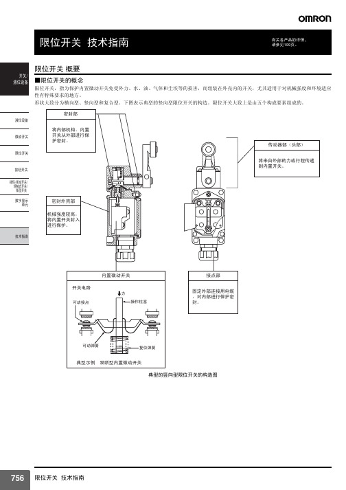
聚酰胺(尼龙)树脂
开关盒 密封橡胶
聚苯硫醚 铝(铸件) 锌(铸件)
丁腈橡胶
硅胶 氟化胶 氯丁二烯橡胶
材料记号 Au AuAg PGS AgPd
Ag
AgNi AgInSn C5210 C1700 C1720 C1700-□M C1720-□M SUS301-CSP SUS304-CSP PF PBTP PETP
接触形式 根据各种用途构成接点的电气输入输出电 路的方式。 树脂固定 (塑封端子) 用导线对端子部分完好配线, 通过充填树 脂使该部分固定, 消除暴露在外的带电部 分, 提高密封性的一种方法。
⚍ ᣛৃࡼ⠛ড䕀ᯊ㾺 ࠄⱘ䞥ሲ䚼ߚˈ䗮䖛 䖭辵㾺ᴹᅲ⦄⬉⇨ 䗮ǃᮁⱘϔ辵䳊ӊDŽ
⚍䯈䱨 ᣛᅮ⚍ৃࡼ⚍ ⱘ䯈䱨ǃ⚍鼠ࡼⱘ䎱 行DŽ
■EN60947-5-1规格用语
对目录中使用的上述规格用语说明如下。
ᓔ݇ ⎆ԡ䆒
⎆ԡ䆒 ᖂࡼᓔ݇ 䰤ԡᓔ݇ ᣝ䪂ᓔ݇ ᢼⷕᢼࡼᓔ݇ 䕏㾺ᓣᓔ݇ 㠍ൟᓔ݇ ᭄ᄫᰒ冫
ऩܗ
ᡔᴃᣛफ
EN60947-5-1 「电气机械控制电路设备」的EN规格。 和IEC60947-5-1的内容相同。 使用范围 开关按用途来分类。 请参考下面的例子。
(1)活塞型 根据密封方法不同,有表中的A型和B型2个种类。 A型是用O型环 或薄膜密封的,由于密封橡胶没有外露,在抵制工作机械的切割碎 屑方面功能较强大,但其反面影响是,有可能会将砂子、切割粉末 等压入活塞的滑动面。B型虽然不会把砂子、切割粉末等压入,且 密封性能优于A型,但由于炽热的切割碎屑飞溅过来,有可能会损 坏橡胶帽。因此,要根据使用场所的不同选用A型或B型。而柱塞 型仍然通过柱塞的往复运动压缩或吸进空气。 为此,如果长时间将柱塞压入,限位开关内的压缩空气逸失,内部 压力将与大气压相同,即使急于让柱塞复位,柱塞却有迟缓复位的 倾向。为了避免发生这种故障,设计时请参见199页。
欧姆龙接近开关说明书
Ẕ⌟⠽ԧⱘ䖍䭓d(mm)
E2K-X8M
䎱 行 10 X嗻 嗼 mm 8
ƶ50 t
X 6
4
2
0
5
10
ഄ䞥ሲ
䴲ഄ䞥ሲ ⦏⩗ 㣃䜮˄ᷥ㛖˅
ϭ⛃䝌˄ᷥ㛖˅
15
20
25
Ẕ⌟⠽ԧⱘ䖍䭓t(mm)
E2K-X15M
䎱 行 25 X嗻 嗼 mm 20
ƶd t=3mm
X
15
10
5
ഄ䞥ሲ
䴲ഄ䞥ሲ
⦏⩗ 㣃䜮˄ᷥ㛖˅ ϭ⛃䝌˄ᷥ㛖˅
1
E2K-C
⦏⩗ 㣃䜮˄ᷥ㛖˅
E2K-X E2K-F
0
5
10
15
20
25
Ẕ⌟⠽ԧⱘ䖍䭓t(mm)
E2K-L
E2KQ-X
E2J
E2K-X8M
䎱 行 10
X嗻 嗼 mm
8
ƶd t=3mm
X
ഄ䞥ሲ
6 䴲ഄ䞥ሲ
4
⦏⩗ 2
㣃䜮˄ᷥ㛖˅
ϭ⛃䝌˄ᷥ㛖˅
0
10 20 30 40 50 60 70
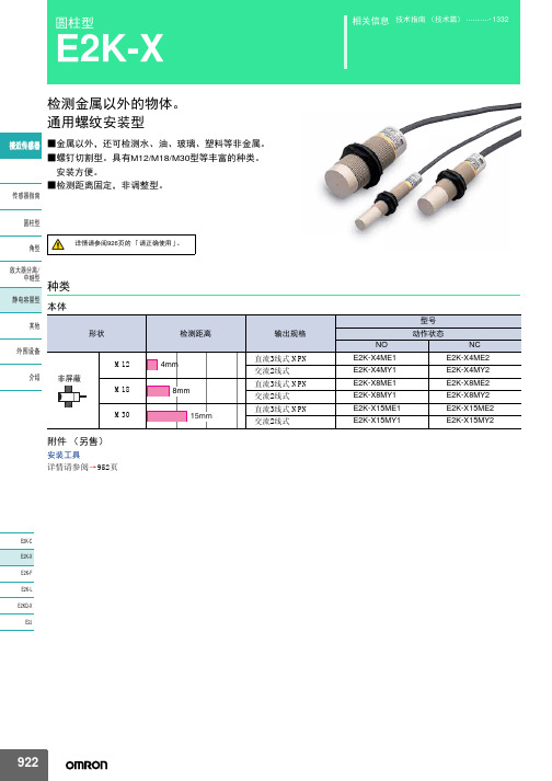
圆柱型
E2K-X
检测金属以外的物体。 通用螺纹安装型
䖥Ӵᛳ఼ ■金属以外,还可检测水、油、玻璃、塑料等非金属。 ■螺钉切割型。具有M12/M18/M30型等丰富的种类。 安装方便。 ■检测距离固定,非调整型。
Ӵᛳ఼ᣛफ
᷅ൟ
详情请参阅926页的 「请正确使用」。
㾦ൟ
ᬒ఼ߚ行
Ё㒻ൟ 种类
䴭⬉ᆍ䞣ൟ 本体
ˆ2. Eൟ˖Ẕ⌟ᰒ冫♃˄㑶˅ Yൟ˖ࡼᰒ冫♃˄㑶˅
䖥Ӵᛳ఼
Ӵᛳ఼ᣛफ ᷅ൟ 㾦ൟ ᬒ఼ߚ行 Ё㒻ൟ 䴭⬉ᆍ䞣ൟ ݊Ҫ ೈ䆒 ҟ㒡
欧米龙 ultra微型基本开关D2QW说明书

Sealed long stroke sliding contact switch with reliable ON/OFF action in severe environmental conditions.•Extra-long stroke. (OT: 2.7 mm)•Clip contacts with highly reliable slide contact mechanism.•Sliding contact allows for quiet operating sound.•High temperature resistance and drip-proof structure for wide range of applications and environmental conditions.•Switch body conforms to IP67•RoHS CompliantOrdering InformationNote:Contact Omron for other terminal or lever configuration and for use in automotive applications. Model Number Legend:Specifications■ CharacteristicsNote:1.Data shown are of initial value.2.For pin plunger models, the above values apply for use at the free position, operating position, and total travel position. For models withlevers, the values apply at the total travel position.■RatingsNote:The resistive load ratings apply under the following test conditions: Ambient T emperature = 20±2°C,Ambient Humidity = 65±5%,Operating frequency = 30 operations/min.■Contact SpecificationsNote:Minimum applicable loads are indicated by N standard refer-ence values. This value represents the failure rate at a 60% (λ60) reliability level (JIS C5003).The equation λ60=0.5 x 10⁻⁶ / operations indicates that a failure rate of 1/2,000,000 operations can be expected at a reliability level of 60%Item SpecificationOperating speed 1 mm to 500 m/sOperating frequency30 operations/minInsulation resistance100 MΩ min. (at 500 V DC)Contact resistance100 mΩ max.Dielectric strength600 V AC, 50/60 Hz for 1 min between terminals of the same polarity1,500 V AC, 50/60 Hz for 1 min between current-carrying metal parts and ground, andbetween each terminal and non-current-carrying metal partsVibration resistance (See note 2)Malfunction: 10 to 55 Hz, 1.5-mm double amplitudeShock resistance (See note 2)Destruction: 1,000 m/s2 max.Malfunction: 300 m/s2 max.Ambient operating temperature–40 to 85 °C (with no icing)Ambient operating humidity95% max. (for 5 to 35°C)Degree of protection IEC IP67 (excluding the terminals on terminal models)Degree of protection against electric shock Class IProof tracking index (PTI)175Life expectancy Mechanical(30 operations/min)500,000 operations min.Electrical(20 operations/min)200,000 operations min. (at 30 V DC 0.1 A) 500,000operations min. (at 14 V DC 10 mA)Weight Approx. 0.7 g (for pin plunger models with terminals) Rated voltage (V)Resistive load30 V DC 14 V DC 0.1 A10 mAItem SpecificationSpecification SlideMaterial Gold platedMinimum applicable load(reference value)1 mA at 5 V DCEngineering Data■Mounting Structure and Reference Positions for Operating CharacteristicsNote:1.All units are in millimeters unless otherwise indicated.■TerminalsTerminal (H)■Contact FormSPST-NODimensions and Operating CharacteristicsNote:1.All units are in millimeters unless otherwise indicated.Mounting Hole Dimensions (Reference)Pin Plunger ModelsCharacteristic Models with posts OF max. 1.5 N {153 gf}OT ref.(2.7 mm)FP max.OPTTP max.9.2 mm 8.4±0.3 mm 5.9 mmSimulated Roller Leaf Lever ModelsD2QW-C073HCharacteristic Models with posts OF max. 1.5 N {153 gf}OT ref.(3.5 mm)FP max.OPTTP max.14.4 mm 12.0±0.5 mm 8.7 mmPrecautionsBe sure to read the precautions and information common to all Snap Action and Detection Switches, contained in the T echnical User’s Guide, “Snap Action Switches, T echnical Information” for correct use.■CautionsDegree of ProtectionIEC Publication 529, degree of protection IP67.Do not use this product in water. Although molded lead wire models satisfy the test conditions for the standard given above, this test is to check the ingress of water into the switch enclosure after submerging the Switch in water for a given time. Satisfying this test condition does not mean that the Switch can be used in water.Do not operate the Switch when it is exposed to water spray, or when water drops adhere to the Switch surface, or during sudden tempera-ture changes, otherwise water may intrude into the interior of the Switch due to a suction effect.Prevent the Switch from coming into contact with oil and chemicals. Otherwise, damage to or deterioration of Switch materials may result.Do not use the Switch in areas where it is exposed to silicon adhesives, oil, or grease, otherwise faulty contact may result due to the generation of silicon oxide.SolderingWhen soldering the lead wire to the terminal, first insert the lead wire conductor through the terminal hole and then conduct soldering. Complete soldering within 3 s using a soldering iron with a capacity of 50 W max. and a tip temperature of 300 °C max.Also, do not apply an external force to the Switch for 1 minute after the completion of soldering.Improper soldering involving an excessively high temperature or excessive soldering time may deteriorate the characteristics of the Switch.When using automatic soldering, solder at at 260 °C max and com-plete soldering with 5 seconds.Side-actuated (Cam/Dog) OperationWhen using a cam or dog to operate the Switch, factors such as the operating speed, operating frequency, push-button indentation, and material and shape of the cam or dog will affect the durability of the Switch. Confirm performance specifications under actual operation conditions before using the Switch in applications.■Correct UseMountingT urn OFF the power supply before mounting or removing the Switch, wiring, or performing maintenance or inspection. Failure to do so may result in electric shock or burning.For M3-screw mounting models, use M3 mounting screws with plane washers or spring washers to securely mount the Switch. Tighten the screws to a torque of 0.29 N·m {3 kgf·cm}. Exceeding the specified torque may result in deterioration of the sealing or damage.For models with posts, secure the posts by thermal caulking or by pressing into an attached device. When pressed into an attached device, provide guides on the opposite ends of the posts to ensure that they do not fall out or rattle.Mount the Switch onto a flat surface. Mounting on an uneven surface may cause deformation of the Switch, resulting in faulty operation or damage.Operating BodyUse an operating body with low frictional resistance and of a shape that will not interfere with the sealing rubber, otherwise the plunger may be damaged or the sealing may deteriorate.HandlingDo not handle the Switch in a way that may cause damage to the sealing rubber.When handling the Switch, ensure that pressure is not applied to the posts in the directions shown in the following diagram. Also, ensure that uneven pressure or pressure in a direction other than the operat-ing direction is not applied to the Actuator as shown in the following diagram. Otherwise, the post, Actuator, or Switch may be damaged, or the service life may be reduced.Wiring Molded Lead Wire ModelsWhen wiring molded lead wire models, ensure that there is no weight on the wire or that there are no sharp bends near the parts where the wire is drawn out. Otherwise, damage to the Switch or deterioration in the sealing may result.Using Micro LoadsEven when using micro load models within the operating range, inrush currents or surges may decrease the life expectancy of the Switch. Therefore, insert a contact protection circuit where neces-sary.MEMOOMRON ON-LINEGlobal - USA - Cat. No. B117-E-01Printed in USAOMRON ELECTRONIC COMPONENTS LLC55 E. Commerce Drive, Suite B Schaumburg, IL 60173847-882-228811/10 Specifications subject to change without noticeAll sales are subject to Omron Electronic Components LLC standard terms and conditions of sale, which can be found at /components/web/webfiles.nsf/sales_terms.html ALL DIMENSIONS SHOWN ARE IN MILLIMETERS.T o convert millimeters into inches, multiply by 0.03937. T o convert grams into ounces, multiply by 0.03527.。
- 1、下载文档前请自行甄别文档内容的完整性,平台不提供额外的编辑、内容补充、找答案等附加服务。
- 2、"仅部分预览"的文档,不可在线预览部分如存在完整性等问题,可反馈申请退款(可完整预览的文档不适用该条件!)。
- 3、如文档侵犯您的权益,请联系客服反馈,我们会尽快为您处理(人工客服工作时间:9:00-18:30)。
用手指按按键传递信号。 手指松开的话信号断开。 因为是手指操作、按触感很重要。
★ 轻触式开关的基本构造
①外壳 ②操作扣 ③垫片 ② ④密封胶圈 ⑤反转弹片 转弹片 ⑥本体 ⑦引线框 ⑥ ⑦ ①外壳ー 外壳ー ②操作扣 ③垫片 ④密封胶圈 ⑤反转弹簧 转弹簧 ⑥本体 ⑦线框 主要部品 各部品有各部品的目的及机能。 各部品有各部品的目的及机能。 为满足这种任 管理是必要的。 为满足这种任务管理是必要的。 本体 引线框 ③ ④ ⑤ 操作扣 垫片 密封胶圈 反转片 ① 部品名 外壳 主要用途(机能) 将开关覆盖。 组合各部品 将操作力传到反转弹簧。 控制密封胶圈。 防止接点部异物侵入。 作为接点传递信号。 确保开关的特性。 确保开关的寿命。 形成接点部。 固定接点及端子部。 作为接点传递信号。 作为端子、在基板上粘付焊锡。
DF有操作按触感的代用特性、
Force
RF
DF大的话操作按触感也会变大。
PT
Stroke
★ 轻触式开关的弱点
防异物性弱
异物 异物
①开关内部异物侵入 ②振动、开关开闭,异物会在接点间移动 ③发生接触不良
B3W、B3WN、B3S 密封性开关根据密封胶圈,防止 异物向接点间侵入。 组立时被侵入就没有意义了。
对象形式 : B3S 基板表面装上开关,进行焊锡。 一般叫回流炉表面实装。 (SMD:Surface Mount Device) 使用奶油焊锡、用热炉将焊锡溶解后,再进行焊锡。 (一般叫热炉焊锡。) 热炉焊锡的情况下、因开关加热量大,所以要使用耐热性好的 树脂。
焊锡
焊锡
★ 形式基准
机种名
①
②
③
④
⑤
工程内的除异物、 产线的清扫 工程内的除异物、生产线的清扫、产品状态(披峰、伤)检查很重要。 的清 品状态 披峰、 检查很重要。 很重要 异物就是・・・成形粉、 异物就是・・・成形粉、紙屑、衣服等的衣纤维、皮屑、灰尘等。 ・・・成形粉 衣服等的衣纤维、皮屑、 纤维
★ 轻触式开关的弱点
大荷重操作弱
微型开关的情况下、操作荷重按原样传递到反转弹簧。 为了夹住操作扣和固定接点、荷重加的过大的话, 反转弹片就会变形、特性低下、耐久性也就下降。
反转弹簧变形
反转弹簧折损
★ OMZ生产品(轻触式开关)
形B3F 形B3W 形B3M
形B3HR
形B3S
形B3WN(新商品)
★ 各开关的特征 开关的特征
形B3F ①构造最标准式轻触式开关 ②台子 ③荷重(OF)有3种 形B3W ①密封式轻触式开关 ②开关的尺寸有6mm和12mm2种 ③荷重(OF)有2种
Cap Cap Coil Spring 确保行程 Case Plunger Spring (Contact) Contact Base Base Lead Fraact
★ 各开关的特征
形B3S ①密封型轻触式开关 ②高密度表面实装的实装轻触式开关 ③接地端子 ④荷重(OF)有2种 形B3WN ①密封防水型轻触式开关 ②压纹胶带
★ 轻触式开关的基本构造
底盖 插入反转弹簧 插入反转弹簧 转弹
端子配列
断面图 断面图
按开关反转弹簧反转的话、蓝色端子和红色端子就通电。 (开关就是ON的状态。)
★ 轻触式开关的基本特性
OF:Operating Force
动作必要力
RF:Releace Force 回复力 DF:Drop DF:Drop Force OF DF 从OF陷入荷重 PT:Pre-travel 到动作的距离
特殊仕样
B 3F B 3W B3HR B 3S B3WN 操作扣状态
操作荷重(OF)
接地端子的有无
开关的形状
根据形式、能判断仕样、形状等。
Cover Plunger Spacer
Cap Push Button Seal Rubber 确保密封性
Seal Rubber 确保密封性 Dome Contact
Plunger
Dome Contact
Base Lead Frame
Base Lead Frame
★ 包装形态
①袋 W-1、B3W-4、B3 对象形式: B3W-1、B3W-4、B3S 象形式:
②胶管
W-1、B3W-4、B3 对象形式 : B3W-1、B3W-4、B3HR
③台子
F-6、B3 对象形式 : B3F-6、B3WN 自动实装用。用实装机进行自动实装基板。 端子变形、胶带偏位的情况下、不能用实装机实装, 也就变成不符合了。
④压纹胶带
对象形式 : B3S 自动实装用。用实装机进行自动实装基板。
Cover Plunger Cover Spacer
Plunger Seal Rubber Dome Contact 确保密封性 Dome Contact Base Base Lead Frame Lead Frame
★ 各开关的特征
形B3M ①长行程密封的轻触式开关 ②旋转弹簧在内部可以确保行程。 形B3HR ①照光密封式轻触式开关 ②非照光、点发光、面发光的3种 ③开关的尺寸有15mm和19mm2种
轻触式开关商品说明 触式开关商品说 开关商品
★ 开关商品群
专用开关 检出开关
轻触式开关
波动开关
拨码开关
各种各样的开关商品群中,OMZ在生产的有轻触式开关、 专用开关、波动开关。 各种各样商品群的形状、使用方法等都不一样。
★ 说起轻触式开关 触式开关・・・ 开关
用途有家电制品、办公机器、手提机器等的操作部(多种多样)
★ 焊锡
F-6、B3W-1、B3W-4、B3HR、B3 对象形式 : B3F-6、B3W-1、B3W-4、B3HR、B3WN 将端子插入孔化基板、在基板里面进行焊锡基板。 一般叫密封孔化。 (THD:Through Hole Device) 焊锡的方法有自动焊锡和手工焊锡。 自动焊锡:涂布松香、自动进行焊锡。 (一般叫流动焊接槽。) 手工焊锡:用烙铁进行焊锡。 焊锡