中星微蓝牙模块中文说明书
KC-01蓝牙模块说明书-VER1.1

KC-01蓝牙模块规格书一.模块功能描述KC-01模块是一个高集成度,低成本,低功耗的蓝牙立体声带通话功能+U盘+TF卡+FM+Line in全功能单芯片模块,符合V4.2+BR+EDR+BLE规范。
1.可播放MP3/WAV;2.蓝牙立体声传输,蓝牙通话;3.支持76-108MHZ FM收音;4.TF/SD卡控制,支持USB功能,可以实现读卡器功能;5.立体声Line-in输入;6.IR遥控;7.两个可控LED、支持外部功放mute功能;8.内部集成电源管理(根据SDK的支持而调整);9、支持U盘控制;10、带高速UART调试及升级接口。
二.模块产品应用该模块主要用于短距离的音乐传输,可以方便地和笔记本电脑,手机,PDA等数码产品的蓝牙设备相连,实现音乐的无线传输,由于集成了FM与MMC卡的播放功能,使本产品具有有极高的性价比。
三.模块产品规格蓝牙版本V4.2+BR+EDR+BLE调制方式PSK 3Mbps,π/4-DQPSK和8DPSK支 持HFP/HSP,OPP,A2DP/AVRCP,PBAP profiles灵敏度(0.1% BER) -85dBm发射功率满足class2 and class3的发射功率要求,可以提供+2dbm的发射功率供电电压DC 3.2V~4.2V耗电电流正常工作电流25mA,播放暂停时12mA信 噪 比>90dB工作温度-20 ~ +50℃尺 寸23mmx13mm x2.05mm四.模块详细尺寸五.模块PIN脚说明PIN脚序号 名称 功能说明1,,24 GND GND2 USBDM USB Negative Data;ISP_DI:3 USBDP USB Positive Data;ISP_DO:PA3 AMUX1L:Simulator Channel 1 Left;Touch10:Touch Input Channel 10;ADC0:ADC Input Channel 0;UART2TXA:Uart2 Data Out(A);ISP_CLK:Wakeup8:Port Interrupt /Wakeup 8; 4PWM0H/ADC0/PA5 UART0TXA:Uart0 Data Out(A);Touch12:Touch Input Channel 12;ADC2:ADC Input Channel 2;IIC_SCL_D:IIC SCL(D);Wakeup9:Port Interrupt /Wakeup 9;5 MIC MIC6 DACR DAC Right Channel7 DACL DAC Left Channel8 VCOMO DAC Reference out9 DACVDD DAC Power10 AGND DAC Ground11 FMIP FMIP12 VDDIO POWER 3.3V13 PB12/SD0CLKGPIO AMUX2R:Simulator Channel2 Right; NFCRX:NFC Data InTouch7:Touch Input Channel 7; ADC11:ADC Input Channel 11;SPI1DOA:SPI1 Data Out(A);SD0CLKB:SD0 Clk(B);14 PB11/SD0CMDGPIO AMUX2L :Simulator Channel2 Left; NFCTX:NFC Data OutTouch6:Touch Input Channel 6; ADC10:ADC Input Channel 10;SPI1CLKA:SPI1 Clk(A);SD0CMDB:SD0 Command(B); Wakeup13:Port Interrupt /Wakeup 13;PB7 GPIO UART0RXB:Uart0 Data In(B); ADC6:ADC Input Channel 6; TMR3:Timer3 Clock Input;15PB10/SD0/DAT/ADC9/PWM3H GPIO UART2RXC:Uart2 Data In(C); Touch5:Touch Input Channel 5; ADC9:ADC Input Channel 9; SPI1_DI A:SPI1 Data In(A);SD0DAT 0B :SD0 Data 0(B); CAP0:Timer0 Capture;16 LDOIN Charge Power 5v 17 VBAT LDO Power18 PR1/ADC12 RTCIO1; ADC12:ADC Input Channel 19PR2/OSC32KORTCIO2; ADC13:ADC Input Channel 13;OSC32KI;20 PR0/OSC32KO/ RTCIO0;OSC32KO21SPI1DOB/SD1CLKA/PC5GPIO ;SD1CLKA :SD1 Clk(A); SPI1DOB :SPI1 Data Out(B); UART2RXD :Uart2 Data In(D) IIC_SDA_B :IIC SDA(B); 22 SPI1CLKB/SD1CMDA/PC4GPIO ;SD1CMDA :SD1 Command(A); SPI1CLKB :SPI1 Clk(B);UART2TXD :Uart2 Data Out(D); IIC_SCL_B :IIC SCL(B); PC2/SD1DAT1A :SD1 Data1(A); UART0TXC :Uart0 Data Out(C); CAP1:Timer1 Capture; 23PWM5L/SPI1DIB/SD1DATA/PC3SD1DAT0A :SD1 Data0(A); SPI 1DI B:SPI 1 Data In(B ); UART0RXC :Uart0 Data In(C)六.应用原理参考七.使用注意事项A.关于无线蓝牙的使用环境,无线信号包括蓝牙应用都受周围环境的影响很大,如树木、金属等障碍物会对无线信号有一定的吸收,从而在实际应用中,数据传输的距离受一定的影响。
LM400蓝牙模块一般性文档说明书

LM400 – Bluetooth Module GeneralThe LM400 is designed to provide Bluetooth 2.0 + EDR function on a small form factor. The Bluetooth function is based on CSR BlueCore4-Ext Bluetooth System, which implements the full speed class 1 Bluetooth operations with full 7 slave piconet support. The interface of LM400 to host system is UART.ContentsLM400 – B LUETOOTH M ODULE G ENERAL______1C ONTENTS________________________________________________1F EATURES_________________________________________________2A PPLICATION______________________________________________2B LOCK DIAGRAM__________________________________________________2E LECTRICAL C HARACTERISTICS______________________________3Absolute Maximum Ratings________________________________________3Recommended Operating Conditions________________________________3General Electrical Specifications____________________________________3R ADIO C HARACTERISTICS – B ASIC D ATA R ATE_________________________4Transmitter, VDD = 3.3 V, Temperature = + 20 °C______________________4Receiver, V DD =3.3 V Temperature = + 20 °C________________________5R ADIO C HARACTERISTICS – E NHANCED D ATA R ATE_____________________6Transmitter, VDD = 3.3 V Temperature = + 20 °C______________________6Receiver, VDD = 3.3 V, Temperature = + 20 °C________________________7H ARDWARE S TRUCTURE_____________________________________8PCB O VERWIEV__________________________________________________8D IMENSIONS_____________________________________________________8PCB___________________________________________________________8PCB Connector__________________________________________________8P IN A SSIGNMENT (PCB C ONNECTOR)__________________________________9R ESET B UTTON___________________________________________________9LED___________________________________________________________9P IN-OUT (MODULE)_______________________________________________10S CHEMATIC______________________________________________11C ONFIGURATION__________________________________________12F ACTORY S ETTINGS______________________________________________12AT C OMMAND S ET_______________________________________________12Features• Bluetooth Ver. 2.0 + EDR certification• Transmit Power up to +18dBm (class1)• Low current consumption:• Hold, Sniff, Park, Deep sleep mode• 3.0V to 3.6V operation• Full Bluetooth Data rate over UART and USB• Support up to 7 ACL l inks and 3 SCO links• Enhanced Data Rate (EDR) compliant for both 2Mbps and 3Mbps modulation modes• Interface: USB, UART & PCM (for voice codec)• SPP, HSP/HFP, HID, DUN firmware are available• Support for 802.1 1 Co Existence• RoHS Compliant• Small outline: 28.3 X 30.0 X2.8 mmApplication• Access point• Domestics and Industrial applications• Personal Digital Assistants (PDA)• Serial Adapter• GPS, PO S, Barcode Reader• Digital camera, Printer& Cellular phone• Cordless handsetBlock diagramElectrical CharacteristicsAbsolute Maximum RatingsStorage Temperature -40 °C +85 °CSupply Voltage (VDD) 2.7 VDC 3.6 VDCSupply Voltage (VCC) 3.0 VDC 3.3 VDCOther Pin Voltage Vss -0.4 VDC VDD +0.4 VDCRecommended Operating ConditionsTemperature -10 °C +70 °CSupply Voltage for UART 3.0 VDC 3.6 VDCSupply Voltage for USB 3.0 VDC 3.6 VDCGeneral Electrical SpecificationsCarrier Frequency 2.402 GHz - 2.480 GHz RF Output Power Measured in 50 Ω15 dBm 16.5 dBm 18 dBm RX sensitivity - -88 dBm -86 dBm Load Impedance No abnormal Oscillation - - 5:1 Input Low Voltage RESET, UART, GPIO, PCM -0.30 VDC - 0.80 VDC Input High Voltage RESET, UART, GPIO, PCM 0.7VDD - VDD+0.3 VDC Output Low Voltage UART, GPIO, PCM - - 0.4 VDC Output High Voltage UART, GPIO, PCM VDD-0.4 - - Average Current Consumption Receive DM1 - 114 mA -Radio Characteristics – Basic Data RateTransmitter, VDD = 3.3 V, Temperature = + 20 °C2.402 15 16.5 18dBm2.441 15 16.5 18 dBm RF transmit power 2.480 15 16.5 18 -6 to +20dBm2.402 - 12 25kHz 2.441 - 10 25kHz Initial carrier frequencytolerance2.480 - 9 25 ± 75 kHz2.402 - 890 1000kHz 2.441 - 870 1000 kHz -20dB bandwidth formodulated carrier2.480 - 820 1000 ≤ 1000kHz 2.402 - ± 10 ± 20kHz 2.441 - ± 10 ± 20 kHz Carrier Frequency Drift(single slot packet DH1)2.480 - ± 10 ± 20 ≤ 25kHz 2.402 - ± 10 ± 20kHz 2.441 - ± 10 ± 20 kHz Carrier Frequency Drift(five slot packet DH5)2.480 - ± 10 ± 20 ≤ 40kHz 2.402 - ± 7 ± 14kHz/50µs 2.441 - ± 7 ± 14 kHz/50µs Drift Rate 2.480 - ± 7 ± 14 ≤ 20kHz/50µs RF power control range16 25 - ≥ 16 dB2.402 145 165 170kHz 2.441 145 165 170kHz f1avg“Maximum Modulation ” 2.480 145 165 170 140< f1avg < 175 kHz2.402 115 150 -kHz 2.441 115 150 -kHz f2maz“Minimum Modulation ” 2.480 115 150 ->115 kHz Adjacent channel transmit power F = F 0 ± 2MHz - -35 -20 ≤ -20 dBm Adjacent channel transmit power F = F 0 ± 3MHz - -45 -40 ≤ -40 dBm Adjacent channel transmit power F > F 0 + 3MHz - -50 -40 ≤ -40 dBm Adjacent channel transmit power F < F 0 - 3MHz - -50 -40 ≤ -40dBmReceiver, V DD =3.3 V Temperature = + 20 °C2.402 - -88 -86dBm 2.441 - -88 -86dBm Sensitivity at 0.1% BER(Single slot packets)2.480 - -88 -86 ≤ -70 dBm2.402 - -88 -86dBm 2.441 - -88 -86 dBm Sensitivity at 0.1% BER(Multi slot packets )2.480 - -88 -86 ≤ -70dBm2.402 - -20 -10dBm 2.441 - -20 -10 dBm Maximum received signal levelat 0.1% BER2.480 - -20 -10≥ -20dBm C/I co-channel - 6 11 < 11 dB - 6 11 ≤ 11 dBm Adjacent channel selectivity C/I F = F 0 + 1 MHz - -4 - ≤ 0 dBm Adjacent channel selectivity C/I F = F 0 - 1 MHz - -4 - ≤ 0 dBm Adjacent channel selectivity C/I F = F 0 + 2 MHz - -38 - ≤ -30 dBm Adjacent channel selectivity C/I F = F 0 - 2 MHz - -23 - ≤ -20 dBm Adjacent channel selectivity C/I F > =F 0 + 3 MHz - -45 - ≤ -40 dBm Adjacent channel selectivity C/I F <= F 0 - 5 MHz - -44 - ≤ -40 dBm Adjacent channel selectivity C/I F =F image - -22 - ≤ -9 dBm F 0 = 2441 MHzMaximum level of intermodulation interference (n = 5)- -30 - ≥ -39 dBmRadio Characteristics – Enhanced Data RateTransmitter, VDD = 3.3 V Temperature = + 20 °C2.402 - 6 -dBm2.441 - 6 -dBm Maximum RF transmit power 12.480 - 7 --6 to +20 dBm Relative transmit power - -1.6 - -4 to +1dB π /4 DQ PSKMaximum carrier frequency stability w 0 - 2 - ≤ ±10 for all blocks kHz π /4 DQ PSKMaximum carrier frequency stability w i - 6 - ≤ ±75 for all packets kHz π /4 DQ PSKMaximum carrier frequency stability | w 0 + w i | - 8 - ≤ ±75 for all blocks kHz 8 DPSKMaximum carrier frequency stability w 0 - 2 - ≤ ±10 for all blocks kHz 8 DPSKMaximum carrier frequency stability w i - 6 -≤ ±75 for all packets kHz 8 DPSKMaximum carrier frequency stability | w 0 + w i |- 8 -≤ ±75 for all blocks kHz RMS DVEM - 7 - ≤ 20 dBm 99% DEVM - 13 - ≤ 30 dBm π /4 DQ PSKModulation Accuracy Peak DEVM - 19 - ≤ 35 dBm RMS DVEM - 7 - ≤ 13 dBm 99% DEVM - 13 - ≤ 20 dBm 8 DPSKModulation AccuracyPeak DEVM - 17- ≤ 25 dBm F> F 0 +3 MHz -<-50 - ≤ -40 dBm F< F 0 -3 MHz -<-50 - ≤ -40 dBm F= F 0 -3 MHz --46 - ≤ -40 dBm F= F 0 -2 MHz --34 -≤ -20 dBm F= F 0-1 MHz - -35-≤ -26 dBm F= F 0+1 MHz - -35-≤ -26 dBm F= F 0+2 MHz --31 - ≤ -20 dBm In-band spurious emissionsF= F 0+3 MHz--33 - ≤ -40 dBm EDR Differential Phase Encoding- No Errors-≥ 99%1Note :Measurement made using a POWER_TABLE entery of TX_PRE 80, INT PA63, EXT PA255. This ensures that the Bluetooth requirements for ACP and those defined by the FCC and ETSI are satisfied over the operating temperature range of -5°C to + 45°C. Although the design is capable of generating in excess of + 18dBm, regulatory compliance over the full temperature range of -5°C to + 45°C will not be satisfied if the transmit power approaches this value.Receiver, VDD = 3.3 V, Temperature = + 20 °Cπ /4 DQ PSK- -87 - dBm Sensitivity at 0.1% BER 8 DPSK - -78 -≤ -70dBmπ /4 DQ PSK- -8 - dBm Maximum received signal level 8 DPSK - -10 -≥ -20dBm π /4 DQ PSK - 10 - ≤ +13dBm C/I co-channel at 0.1% BER8 DPSK - 19 - ≤ +21dBm π /4 DQ PSK - -10 - ≤ 0dB Adjacent channel selectivity C/I F = F 0 + 1 MHz 8 DPSK - -5 - ≤ +5dB π /4 DQ PSK - -11 - ≤ 0dB Adjacent channel selectivity C/I F = F 0 - 1 MHz 8 DPSK - -5 - ≤ +5dB π /4 DQ PSK - -40 - ≤ -30dB Adjacent channel selectivity C/I F = F 0 + 2 MHz 8 DPSK - -40 - ≤ -25dB π /4 DQ PSK - -23 - ≤ -20dB Adjacent channel selectivity C/I F = F 0 - 2 MHz 8 DPSK - -20 - ≤ -13dB π /4 DQ PSK - -45 - ≤ -40dB Adjacent channel selectivity C/I F > =F 0 + 3 MHz 8 DPSK - -45 - ≤ -33dB π /4 DQ PSK - -45 - ≤ -40dB Adjacent channel selectivity C/I F <= F 0 - 5 MHz 8 DPSK - -45 - ≤ -33 dB F 0 = 2405, 2441, 2477 MHzπ /4 DQ PSK - -20 - ≤ -7dB Adjacent channel selectivity C/I F =F image 8 DPSK - -15 - ≤ 0dBHardware StructurePCB Overwiev DimensionsPCBUnit: mmPCB ConnectorUnit: mmPin Assignment (PCB Connector)Direction Description Signal Level1 GND Power Ground Ground2 TXD Output UART Data Out TTL3 RXD Input UART Data Input TTL4 RTS Output UART Ready to Send TTL5 CTS Input UART Clear to Send TTL6 VDD Input DC Input (3.0–3.3 V) Power7 Data led** Input Data Transfer (Active Low) TTLSpecified TTL8 Status* Output Not9 DSR* Input Data Set Ready TTL10 DTR* Output Data Terminal Ready TTL11 RST Input Reset (Active Low) TTL12 GND Power Ground Ground* = Not in use** = Indicates transmitting/receiving data over an established Bluetooth connectionReset ButtonBy pressing the Reset button you can• disconnect and reconnect a wireless connection (short press)• restore the default Baud Rate, 19 200 bps (> 3 s press)LEDThe LED indicates when a Bluetooth connection is established.Pin-out (module)1 GND GND Common ground2 PVCC Power Power Amp. Power Supply (3.3V)3 AIO (0) Bi -directional Programmable I/O terminal , 32KHz sleep clock input4 AIO (1) Bi -directional Programmable I/O terminal5 PIO (0) Bi -directional Programmable I/O terminal , RX Enable6 PIO (1) Bi -directional Programmable I/O terminal , TX Enable7 PIO (2) Bi -directional Programmable I/O terminal , USB_PULL_UP , CLK_REQ_OUT8 PIO (3) Bi -directional Programmable I/O terminal , USB_WAK E_UP , CLK_REQ_IN9 PIO (4) Bi -directional Programmable I/O terminal , USB_O N , BT_Priority/Ch_Clk output for co-existence signalling10 GND GND Common ground11 PIO (5) Bi -directional Programmable I/O terminal , USB_DETAC H , BT_Active output for co-existence signalling12 PIO (6) Bi -directional Programmable I/O terminal , CLK_REQ ,WLAN_Active/Ch_Data input for for co-existence signalling13 PIO (7) Bi -directional Programmable I/O terminal14 PIO (8) Bi -directional Programmable I/O terminal15 PIO (9) Bi -directional Programmable I/O terminal16 RESET CMOS input Reset input of module, Active low reset17 VCC Power Module power supply input18 GND GND Common ground19 GND GND Common ground20 USB_DP Bi-directional USB data plus21 USB_DN Bi-directional USB data minus22 PCM_SYNC Bi-directional Synchronous data sync23 PCM_IN CMOS input Synchronous data input24 PCM_OUT CMOS output Synchronous data output25 PCM_C LK Bi -directional Synchronous data clock26 UART_RX CMOS input UART data input27 UART_TX CMOS output UART data output28 UART_RTS CMOS output UART request to send (active low)29 GND GND Common ground30 UART_CTS CMOS input UART clear to send (active low)31 SPI_MOSI CMOS input Serial Peripheral Interface data input32 SPI_CSB CMOS input Chip select for Synchronous Serial Interface (active low)33 SPI_CLK CMOS input Serial Peripheral Interface clock34 SPI_MISO CMOS output Serial Peripheral Interface data output35 PIO (11) Bi-directional Programmable I/O terminal36 PIO (10) Bi-directional Programmable I/O terminal37 RF_IO Analogue Antenna interface38 GND GND Common groundSchematicConfigurationYou can reprogram the default settings on the module using AT commands (see section below AT Command Set) or the Wireless Bluetooth Configuration Utility firmware (see separate manual).Factory Settings• Baud rate: 19 200 bps• Data bit: 8• Parity: None• Stop bit: 1• Flow control: HW• Others: See section AT Command SetAT Command SetThe following is the AT command set for the module in the command mode (that is, when the module is in the disconnection state).The commands will be preceded by “AT” to be executed. (Ex: To execute the address inquiry, “B?”, use “ATB?”)All the commands and parameters are case insensitive.+++ Escape sequence with guard time. When the device is in Data mode, it can be forced back into Command mode while maintaining the connection to the remote device. The characters should then be sent 1 second apart.A This command is used to establish a connection.Available only when the adapter is in the master role.A Connect the adapter to a specified Bluetooth device. Available only when “ATD=xxxxxxxxxxxx” is executed.A1-A8 Connect the adapter to a Bluetooth device in the neighborhood found through “ATF?”B This command is used to display the Bluetooth address of the local adapter.B? Inquire the Bluetooth address of the local adapter.C This command enable or disable flow control signals (CTS/RTS) of theUART port.C0 Disable flow control.(default) C1Enable flow control.C? Inquiry of current setting.D For security purpose, this command is used to specify a unique remoteBluetooth device to be connected.In the master role, the adapter pairs and connects with the designatedremote slave address.If the adapter is in the slave mode, this command is a filter condition toaccept the inquiry of the master device.D=xxxxxxxxxxxx "xxxx-xx-xxxxxx" is a string of 12 hexadecimal digits.D0 Restore the status in which the adapter can connect with any remote address.D? Inquiry the designated address that can be paired and connected.E This command is used to specify whether the adapter echoes charactersreceived from the UART back to the DTE/DCE.E0 Command characters received from the UART are not echoed back to the DTE/DCE.(default) E1Command characters received from the UART are echoed back to theDTE/DCE.E? Inquire the current setting.F This command is used to search for any Bluetooth device in theneighborhood within one minute. If any device is found, its name andaddress will be listed. The search ends with a message “Inquiry ends. Xxdevice(s) found.”Available only when the adapter is in the master role and manuallyconnected (see command “O”).F? Inquire Bluetooth devices in the neighborhood.H This command can drop the connection either in master or slave role. It isalso used to specify whether the adapter can be discovered or connected byremote devices.H Drop current connection.H0 The adapter enters the undiscoverable mode. If a pair has been made, the original connection can be resumed. But other remote master device cannot discover this adapter. Reboots when set.(default) H1The adapter enters the discoverable mode. Reboots when set.H? Inquire the current setting.I This command is used to inquire the firmware version and other settings.I0 Inquire the version codes.I1 Inquire all current settings.I2 Inquire status on RSSI at Online Command Mode.K This command is used to specify number stop bits of COM port.(default) K0 One stop bit.K1 Two stop bits.K? Inquire the current setting.L This command is used to specify the baud rate of COM port.L0 4800 bpsL1 9600 bps(default) L2 19200 bpsL3 38400 bpsL4 57600 bpsL5 115.2 kbpsL6 230.4 kbpsL? Inquire the current baud rate.M This command is used to specify parity bit setting of COM port.(default) M0 None parity bit.M1 Odd parity.M2 Even parity.M? Inquire the current setting.N This command is used to specify a name for the adapter.You can specify a friendly name using 0 to 9, A to Z, a to z, space and -,which are all valid characters. Note that “space” and “-” are not permittedfirst or last in the name. The default name is “Serial Adaptor”.N=xxxxxx "xxxxxx" is a character string with a maximal length of 16.N? Inquire the name of the local adapter.O This command directs the device to switch from Command mode to Online data mode. It is also used enable/disable auto-connection feature (availableonly when the adapter is in the master role).O Switch from Command mode to Online Data mode.(default) O0 Automatically connect the adapter to a device specified by “ATD”, or any available device if “ATD” is not executed. Reboots when set.O1 Disable auto-connection feature. After it is executed, you need to execute “ATA” to manually connect a remote device. Reboots when set.O? Inquire the current setting.P This command is used to specify a PIN. The default PIN is “1234". Paired adapters should have a same PIN.P=xxxx "xxxx" is a 4–8-digit string.P0 Cancel authentication by PIN.P? Inquire the current PIN.Q The command is used to set if result messages are prompted when ATcommands are executed.The result messages are: OK/ERROR for command execution, orCONNECT/DISCONNECT for connection status.(default) Q0Result messages are prompted.Q1 Result messages are not prompted.Q? Inquire the current setting.This command is used to specify whether the adapter is in the master or Rslave role.If the device role is changed, the adapter will reboot and all pairedaddresses will be cleared.R0 Set the adapter to the master role.(default) R1Set the adapter to the slave role.R? Inquire the current role of the adapter.S This command is used to enable/disable auto-power saving feature ofRS232 driver.S0 Disable RS232 force on (auto power down) mode.(default) S1Enable RS232 force on (auto power down) mode.S? Inquiry of current setting.X Disable/Enable escape sequence (+++).X0 Disable escape sequence.(default) X1Enable escape sequence.X? Inquiry of current setting.Z This command is used to restore the default settings andoriginate a warm start.Z0 Restore the default settings.。
蓝牙模块说明书

EPBMX 蓝牙串口模块使用说明目录:1、产品概述2、电路接口3、主要性能4、模块基本使用说明(电压、协议、尺寸、波特率等说明)5、状态说明(配对状态等、如何放弃记忆的配对地址重新记忆等)6、AT 命令集(用户可修改波特率、用户名等)1、 产品概述EPBMX-COM 蓝牙串口核心模块采用CSR 公司的BlueCore4-External 蓝牙芯片,V2.0协议标准,工业级标准26.9mm x 13 mm x 2.2mm,体积尺寸紧凑,自带高效板载天线,透明串口,可与各种蓝牙适配器、蓝牙手机配对使用,也可主从一对使用。
出厂时默认软件包含AT 命令集,详见第6点说明。
EPBMX 模块外观及管脚图2、电路接口:RS232串行口(TTL 电平)、电源接口、连接状态信号口、主机模块含“放弃原记忆的从机模块地址重新搜寻模块”信号引脚。
3、主要性能:频段:2.40GHz—2.48GHz ,ISM Band蓝牙协议:BlueTooth V2.0协议标准功率等级:Class2(+6dBm )接收灵敏度:-85dBm操作电压:3.3V(极限电压2.7V~4.2V)工作温度: -40℃ 至 +105℃参考功耗:等待搜索时 35 mA连上线时 约8 mA4、模块基本使用说明:1、 采用CSR主流蓝牙芯片,蓝牙V2.0协议标准2、 蓝牙串口核心模块 EPBMX-COM 工作电压:2.7-3.3V。
3、 蓝牙芯片采用向前纠错编码,通信效率更高,自动跳频,抗干扰能力强。
4、 波特率为1200,2400,4800,9600,19200,38400,57600,115200,230400,460800,921600,1382400用户可设置5、 核心模块尺寸大小为:26.9mm x 13 mm x 2.2mm,工作电源3.3V。
6、 工作电流:35mA/8mA7、 休眠电流:不休眠。
8、 用于GPS导航系统,水电煤气抄表系统,工业现场采控系统,蓝牙打印机,蓝牙手机医疗监控,其他无线模块应用场合。
RC-CC1352-XXX 模块说明书

8
DIO-6
GPIO, Sensor Controller, High drive capability
9
DIO-7
GPIO, Sensor Controller, High drive capability
10
DIO-8
GPIO Digital
DIO-9
GPIO Digital
12
DIO-10
(*) If not specified, the default version is with PCB streap antenna
Applications :
Feature :
- Low-Power Wireless Systems
- IEEE 802.15.4g mode switch support
DIO-17/JTAG-TDI 24
DIO-16/JTAG-TD0 23
JTAG-TCKC
JTAG-TMSC
Mechanical dimensions
19.98mm
29.90mm
1.27mm
3.0mm±0.2
Radiocontrolli s.r.l refuses any responsibility for irregular uses of the devices and for any possible lack or inaccuracy of the data and reserves the right to change in whole or in part these information without notice.
Pag. 3 / 6 Rev 1.5
RRCC-C-CCC1113015102-S-XPXI-X434
蓝牙模块使用说明书
蓝牙模块使用说明一、模块简介:1、芯片简介该蓝牙模块采用台湾胜普科技有限公司的BMX-02X模块为核心,它采用CSR BLUEcore4-External芯片并配置8Mbit的软件存储空间,成本低,使用方便。
CSR BlueCore4是英国Cambridge Silicon Radio(CSR)公司日前推出的第四代蓝牙硅芯片。
这种硅芯片用于蓝牙技术推广小组(SIG)推出的增强数据传输率(EDR)蓝牙。
CSR的BlueCore4的数据传输率将比现有的v 1.2蓝牙装置快三倍,并且使蓝牙移动电话或手机的耗电量较低。
蓝牙EDR的最大数据传输率为每秒2.1兆比特,而目前v1.2标准传输率则为每秒721千比特。
传输率的提高意味着对一个特定量的数据来说,EDR无线电的工作将比v1.2无线电快三倍,从而减少耗电量,大大有利于依赖蓄电池的移动设备。
CSR BlueCore4完全能与现有蓝牙v1.1和v1.2装置兼容。
蓝牙EDR用一种相移键控(PSK)调制模式取代标准传输率的Gaussian频移键控(GFSK),实现更高的数据传输率。
CSR BlueCore4正在以两种形式提供——一种用于外部“快闪”存储器,一种用于掩模ROM。
BlueCore4-External以一种8×8mm BGA(球形格栅矩阵)封装提供,是十分灵活的解决方案,能够适应迅速更新的市场。
例如,由于BlueCore是目前可以得到的唯一能够支持蓝牙v1.2规格的所有强制和可选功能的硅芯片,BlueCore4-External为PC应用程序提供了理想的解决方案,使它们得益于以三倍速度的传输率无线传输文件,或者同时操作多个高需求的蓝牙链路。
鉴于蓝牙固件安装在芯片只读存储器上,CSR BlueCore4-ROM 的成本较低,占用面积小得多(在小片尺寸包装中为3.8×4mm,在与BC2-ROM和BC3-ROM引脚兼容的BGA中为6×6mm)。
蓝牙模块应用必读

蓝牙模块应用必读
双击自动滚屏发布者:admin 发布时间:2008-3-12 10:49:48 【字体:大中小】
购买蓝牙模块的用户,使用中请注意以下几点:
1、供电问题:蓝牙模块供电为3.3V,百米蓝牙模块供电采用两级供电,包括VCC和PAVCC,其中PAVCC 是功率扩展电源,使用中一定要两个都供给3.3V。
2、接地问题:模块中有多个GND引脚,使用中应将全部GND接地。
3、PIO引脚指示问题:在模块应用中,有的PIO是蓝牙模块工作状态指示,建议您最少引出一个做为工作状态监测引脚,如PIO5,未建链时输出800ms的脉冲信号,建链后输出200ms的脉冲信号,详细引脚功能定义请参考相应免费蓝牙固件应用说明。
4、音频应用:
音频应用中,如果您的电路板上有别的音频电路,建议将蓝牙模块单独稳压供电,减少干扰噪声。
蓝牙模块的MIC输入与SPK输出采用平衡电路接法,与外围电路连接时需要平衡非平衡转换器件,详细请看最新音频电路参考设计。
5、不用的引脚:模块中可能有许多你不需要的引脚,不用的引脚一律悬空。
6、SPI接口:SPI接口是模块固件升级和参数修改有接口,共4条线,在布设PCB板时,建议引出焊盘,便于今后固件维护。
7、GC-05/06的兼容问题:GC-05是百米蓝牙模块,GC-06是10米蓝牙模块,两者引脚完全兼容,建议您在PCB布板时,按GC-05设计,然后按需要插入GC-05、06都可以,这样在产品应用中更换10米100米不同功率的模块时,更方便。
蓝牙模块使用说明
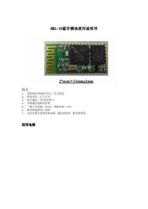
HKL HKL--1010蓝牙模块使用说明书蓝牙模块使用说明书蓝牙模块使用说明书简介1, 采用GSR主频蓝牙芯片,V2.0协议2, 供电电压:2.7-3.3V3, 串口通信,TTL电平串口。
4, 多种通信波特率设置5, 一般工作电流:35mA,休眠电流:1mA6, 配对初始密码:04387, 支持AT指令设置设备名称、通信波特率、配对密码等。
应用电路应用电路AT AT命令集命令集命令集a 提示:如果按出厂的默认波特频率使用,不想修改波特率的下面的内容可不需理会:本AT命令用于主机和从机.成对方式使用时,主机和从机可以不同波特率也能传数据,但主机和主机相连的设备波特率要相同,从机和从机相连的设备也要同波特率.b 设置硬件连接:在发送AT命令之前确保硬件连接如下:把带底版的八PIN接口,第一脚接外接电源(3.3至5V),第六脚接电脑COM1(DB9公头)口的第三脚, 第七脚接电脑COM1口第二脚,第八脚接电脑COM1口第五脚.C 设置方式:初始通讯参数为9600,N,8,1,在配对之前(即配对指示灯闪烁时或PIO3闪动时)发送修改波特率命令使用超级终端或串口调试助手打开电脑COM1口,输入文本"AT"进行手动发送.1 测试通讯发送:AT(返回OK,一秒左右发一次)返回:OK2 改蓝牙串口通讯波特率发送:AT+BAUD1返回:OK1200发送:AT+BAUD2返回:OK2400......1 12002 24003 48004 96005 192006 384007 576008 1152009 230400A 460800B 921600C 1382400不建议用在超过115200的波特率,因为大多系统都没有115200波特率.设置超过115200后用电脑无法使用,要用单片机编程于高于115200才能使用此波特率和重新发AT命令设低波特率,否则无法恢复到低波特率了.用AT命令设好波特率后,下次上电使用不需再设,可以掉电保存波特率.3 改蓝牙名称(2008年2月24日后新增功能)发送:AT+NAMEname返回:OKname参数name:所要设置的当前名称,即蓝牙被搜索到的名称.20个字符以内.例:发送AT+NAMEbill_gates返回OKname这时蓝牙名称改为bill_gates参数可以掉电保存,只需修改一 次.PDA端刷新服务可以看到更改后的蓝牙名称.4 改蓝牙配对密码发送:AT+PIN****返回:OKset p in参数****:所要设置的配对密码,4个字节,此命令可用于从机或主机.从机则是适配器或手机弹出要求输入配对密码窗口时,则手工输入此参数就可以连接从机.主机则是在主蓝牙模块连数码相机时,数码相机是从机,找到相机的配对密码,再设入主蓝牙模块,则主蓝牙模块就可以自动连接相机.例:发送AT+PIN8888返回OKset p in这时蓝牙配对密码改为8888,模块在出厂时的默认配对密码是1234.参数可以掉电保存,只需修改一次.封装图封装图使用方法该模块为蓝牙从设备,可与各类手机、电脑等蓝牙配对使用,下面仅以计算机用蓝牙适配器为例,说明使用方法与步骤:1 安装蓝牙适配器服务程序打开“Bl u es o leil_3.2_V o IP_C h ina_070406”,安装里面的文件"set up",安装完后吧破解文件夹内的两个文件覆盖到安装目录下。
BT-HC05-V1.0蓝牙模块用户手册

通讯中:5~20mA
(根据串口通讯频繁度不同而不同)
模块展示
主
简
从
单
一
易
体
用
名称 VCC GND TXD RXD KEY LED
引脚说明
说明 电源(3.3V~5V)
地 模块串口发送引脚(TTL电平,不能接RS232电平) 模块串口接收引脚(TTL电平,不能接RS232电平) 高电平进入AT状态,低电平或者悬空则进入正常状态。
参数说明
名称 接口说明 波特率 通讯距离 对外接口 工作电压
工作电流
参数 TTL电平,兼容3.3v/5v单片机 4800/9600(默认)/19200/38400/57600 /115200/230400/460800/921600/138240 10m(空旷地) 6pin排针(2.54间距) 3.3V~5V 配对中:30~40mA;
配对成功输出高电平,未成功输出低电平。
与单片机或者串口转USB模块连接方式
1.蓝牙模块与串口转USB模块对接连接方式:
USB
5v 3.3v
USB转TTL TXD RXD
蓝牙模块
GND
VCC
2.蓝牙模块与单片机通讯:
单片机
VCC TXD RXD
GND
LED
KEY
RXD TXD
常用AT指令
使用AT指令之前要进入AT指令模式。 建议进入AT指令模式的方式:上电前将KEY引脚连接到高电平,然后再上电。 进入AT指令后,波特率为38400(8位数据位,1停止位)。
指令1:修改蓝牙模块名字:AT+NAME=<name><回车>
例如:AT+NAME=Beetle<回车> 模块返回:0K
- 1、下载文档前请自行甄别文档内容的完整性,平台不提供额外的编辑、内容补充、找答案等附加服务。
- 2、"仅部分预览"的文档,不可在线预览部分如存在完整性等问题,可反馈申请退款(可完整预览的文档不适用该条件!)。
- 3、如文档侵犯您的权益,请联系客服反馈,我们会尽快为您处理(人工客服工作时间:9:00-18:30)。
℃ ℃
V
6
WS9621NLSC_MODULE
7.封装信息:
8.典型应用电路:
7
WS9621NLSC_MODULE (1)基本应用电路
8
WS9621NLSC_MODULE (2)单功放应用电路
9
WS9621NLSC_MODULE (3)双功放应用电路
9 模块工作流程:
11
10 已知问题列表
(1) (2) (3) (4) 部分手机的播放器由于兼容性的问题,播放音乐时无上一曲下一曲功能. 非正常断电的情况下,Bluetooth Module 不支持自动回连功能. 上电的瞬间音频的输出端有短暂的悬空状态,音箱极有可能会发出一点电流声. 当机内配对列表中存在已配对的设备,自动回连动作可能与手机端配对动作发生 冲突导致偶尔的配对失败现象。
WS9621NLSC_MODULE
Bluetooth Module for WS9621NLSC
Datasheet Version 1.0
版本说明
版本号r V1.0 日期 2012-8-30 创建者 Sun xuefeng 版本说明 初始版本
1
WS9621NLSC_MODULE
2
WS9621NLSC_MODULE
Power Supply Current (With a normal 3.7V battery voltage)
Recommended Operating Conditions
Storage temperature Operating temperature range Supply voltage: VBAT
2. 主要应用:
支持降噪功能的蓝牙立体声耳机 无线立体声音箱
3. 功能要求:
完全支持Bluetooth v3.0 + EDR. . RF性能表现突出。 双麦克输入 最新的音频算法能够改善通话和音乐质量。 3.0-5.5V电池供电,3.0-6.5V适配器或USB供电。 UART端口最高可支持3M调制模式。
3
WS9621NLSC_MODULE
4. 模621NLSC_MODULE
5. 模块管脚说明
管脚编号 1 2 3 4 5 6 7 8 9 10 11 12 13 14 15 16 17 18 19 20 21 22 23 24 25 26 27 28 29 管脚标号 GND VBAT_IN CHGND GND VCHGER GND GND PWR GND SPK_R SPK_L GND MBIAS MICLP MICLN MICRP MICRN GND GPIO0 GPIO1 GPIO2 GPIO3 GPIO5 GPIO6 GPIO7 DVDD33 GPIO9 GPIO8 GPIO4 功能描述 接地端 电池正极接入端 充电地端 接地端 充电接入端(5V) 接地端 接地端 上电复位,高电平(电池电压)表示按键开启 接地端 右声道音频输出 左声道音频输出 接地端 麦克风偏置电压输出,外接2.2uF电容 麦克风左声道输入,正极 麦克风左声道输入,负极 麦克风右声道输入,正极 麦克风右声道输入,负极 接地端 通用输入输出 通用输入输出 通用输入输出 通用输入输出 通用输入输出 通用输入输出 通用输入输出 3.3V输出 通用输入输出 通用输入输出 通用输入输出
5
WS9621NLSC_MODULE
30 31 32 33 34 GND GND RF GND GND 接地端 接地端 RF接口 接地端 接地端
6.电气特性:
RF specifications
Parameters Frequency Range Rx sensitivity Maximum Output Power Output power range Parameters A2DP Active Mode Single HFP Sniff Deep Sleep (off) Mode Mode and Conditions Class 2 Mode and Conditions Min 2402 -3 -30 Min Typ -80 2 Typ 18 410 5.0 Max 2480 -90 4 4 Max Unitz MHz dbm dbm dbm Unitz mA uA uA
1. 产品概述:
本规格书适用于 WS9621NLSC 蓝牙模块。WS9621NLSC 蓝牙模块为本公司自主开发的无线音频 数据传输产品,是基于蓝牙协议的立体声无线传输模块,该模块能够满足高效率、低成本、低功耗和 体积小巧的蓝牙产品设计。同时,该模块方案完全符合 Bluetooth version 3.0+EDR 规范。
(1) 模块上电(电池供电 3.7-4.2V 或者 USB 供电 5V)。 (2) 长按 PWR 键开机,LED1 和 LED2 交替闪烁,说明已经进入可配对状态,可与 蓝牙设备配对连接。 (3) 如果上次配对设配在线,蓝牙模块上电开机进入可配对模式后会自动进行回连。
10
WS9621NLSC_MODULE (4) 将上次配对设备蓝牙关闭,蓝牙模块上电开机进入可配对模式后可与其他设备配 对连接。 (5) 本模块如果已经和蓝牙设备建立连接后,可以传送蓝牙设备的音乐,通过按键控 制音乐的上,下曲,音量加,减,以及暂停,播放等动作,具体按键功能可以通 过软件进行配置。我们可以提供单按键,三按键和五按键等方案。 (6) 如果跟手机蓝牙设备建立了连接,有来电时,通过短按 PWR键来接通和挂断来 电。 (7) 本模块可以外接少许电容接入双麦克,更好的进行降噪处理,使通话质量更佳。