– Scene Geometry – Scene Appearance
实拍与CG合成教程

实拍与CG合成实拍与虚拟的CG制作各有利弊,实拍的素材拥有丰富的细节和真实的质感、光照等信息,但有一些人工难以搭建的场景,演员难以表演的动作等却成了实拍的瓶颈;而CG制作拥有更大的艺术加工空间,更强的可控性,但真实性的缺乏会很容易让观众看出穿帮的地方。
但随着电影电视对高难度视觉冲击的依赖,以及CG制作水平的提高,实拍与CG场景、CG角色和同台演出越来越频繁的出现在我们的视线中,如下图所示:加勒比海盗中实拍的演员表演,对演员的动作表情等进行跟踪,在maya等三维软件中制作最终的怪物模型,进行动画,最后进行合成,替换原始实拍的演员,就呈现出了我们看到的影片镜头。
加勒比海盗中实拍的演员表演,对演员的动作表情等进行跟踪,在maya等三维软件中制作最终的怪物模型,进行动画,最后进行合成,替换原始实拍的演员,就呈现出了我们看到的影片镜头。
以上的影片镜头除了使用了跟踪与合成技术之外,还大量使用了动作捕捉、3S皮肤表现,整体矫色等多种技术,本篇教程重点讨论的是其中的跟踪与合成部分,至于其它方面的技术请读者查看CG98中其它的教程或在网络上查找。
下面看一下本篇教程使用的实例:作者为自己的模型制作台拍摄了一段视频文件,这是其中的一张截图。
教程里会在这段视频中添加入Maya制作的模型,让虚拟的模型就如同真实摆放在桌子上一般。
最终效果截图入下:在开始讲解制作过程前首先需要了解一下什么是跟踪,为什么需要跟踪。
所谓的跟踪是通过分析视频画面中的众多象素点的相对运动在虚拟的三维环境中还原摄像机的运动。
比如我们拍摄时抱着摄像机一步步向前走靠近拍摄物体,这样拍摄出来的镜头在进行跟踪之后,软件会创建一个虚拟的摄像机,它的运动同样也是向前的。
这就是跟踪软件的工作方式。
(至于软件是如何根据像素的相对运动来推算摄像机的运动,请参考《图形图象学》等书籍。
)但跟踪只是一个中间过程,我们最终需要的是让虚拟的角色与拍摄的影片进行互动。
现在我们有了虚拟的摄像机而且运动方式同真实拍摄时一致。
Maya菜单中英文对照,Maya快捷键大全

Maya菜单中英文对照,Maya快捷键大全Maya菜单中英文对照,Maya快捷键Maya2008较常用的快捷键1--显示方式为最粗糙2--显示方式为中等3--显示方式为最好4--显示方式为线框模式5--显示方式为实体模式6--显示方式为纹理模式7--显示方式为灯光模式其中1,2,3只有在NURBS下才能正常显示q--选择工具w--移动工具e--旋转工具r--缩放工具t--操纵器视图操作快捷键Alt+左键--旋转视图(三个正交视图不可用)Alt+中键--平移视图Alt+右键--推拉视图快速敲击空格键--视图切换长按空格键不放--显示所有菜单**MAYA**快捷键大全。
学MAYA的不能错过Enter 完成当前操作~ 终止当前操作Insert 插入工具编辑模式W 移动工具e 旋转工具r 缩放工具操纵杆操作y 非固定排布工具s 设置关键帧i 插入关键帧模式(动画曲线编辑)Shift E 存储旋转通道的关键帧Shift R 存储缩放通道的关键帧Shift W 存储转换通道的关键帧Shift Q 选择工具,(切换到)成分图标菜单Alt q 选择工具,(切换到)多边形选择图标菜单q 选择工具,(切换到)成分图标菜单t 显示操作杆工具= 增大操纵杆显示尺寸- 减少操纵杆显示尺寸窗口和视图设置移动被选对象快捷键功能解释快捷键功能解释Ctrl a 弹出属性编辑窗/显示通道栏a 满屏显示所有物体(在激活的视图)f 满屏显示被选目标Shift F 在所有视图中满屏显示被选目标Shift A 在所有视图中满屏显示所有对象' 设置键盘的中心集中于命令行空格键快速切换单一视图和多视图模式Alt ↑ 向上移动一个象素Alt ↓ 向下移动一个象素Alt ← 向左移动一个象素Alt → 向右移动一个象素Alt '设置键盘中心于数字输入行播放控制选择物体和成分快捷键功能解释快捷键功能解释Alt 。
在时间轴上前进一帧Alt ,在时间轴上后退一帧. 前进到下一关键帧, 后退到上一关键帧Alt v 播放按钮(打开/关闭)Alt/Shift V 回到最小帧K 激活模拟时间滑块F8 切换物体/成分编辑模式F9 选择多边形顶点F10 选择多边形的边F11 选择多边形的面F12 选择多边形的UVsCtrl I 选择下一个中间物体Ctrl F9 选择多边形的顶点和面显示设置快捷菜单显示快捷键功能解释快捷键功能解释鼠标左键4 网格显示模式5 实体显示模式6 实体和材质显示模式7 灯光显示模式d 设置显示质量(弹出式标记菜单)空格键弹出快捷菜单(按下)空格键隐藏快捷菜单(释放)Alt m 快捷菜单显示类型(恢复初始类型)1 低质量显示2 中等质量显示3 高质量显示] 重做视图的改变[ 撤消视图的改变Alt s 旋转手柄附着状态翻越层级文件管理快捷键功能解释快捷键功能解释↑ 进到当前层级的上一层级↓ 退到当前层级的下一层级← 进到当前层级的左侧层级→ 进到当前层级的右侧层级Ctrl N 建立新的场景Ctrl O 打开场景Ctrl S 存储场景1 桌面文件管理(IPX版本专有)0雕刻笔设置菜单模式选择快捷键功能解释快捷键功能解释Alt f 扩张当前值Ctrl m 显示(关闭)+主菜单Alt r 激活双重作用(开启/关闭)鼠标右键h 转换菜单栏(标记菜单)Alt a 显示激活的线框(开启/关闭)F2 显示动画菜单Alt c 色彩反馈(开启/关闭)F3 显示建模菜单鼠标左键u 切换雕刻笔作用方式(弹出式标记菜单)F4 显示动力学菜单o 修改雕刻笔参考值F5 显示渲染菜单b 修改笔触影响力范围(按下/释放)吸附操作m 调整最大偏移量(按下/释放)快捷键功能解释n 修改值的大小(按下/释放)C 吸附到曲线(按下/释放)/ 拾取色彩模式--用于:绘制成员资格、绘制权重、属性绘制、绘制每个顶点色彩工具X 吸附到网格(按下/释放) ,选择丛(按下/释放)-用于绘制权重工具V 吸附到点(按下/释放)编辑操作(显示/隐藏)对象快捷键功能解释快捷键功能解释z 取消(刚才的操作)Ctrl h 隐藏所选对象Shift Z 重做(刚才的操作)Ctrl/Shift H 显示上一次隐藏的对象g 重复(刚才的操作)三键鼠操作Shift G 重复鼠标位置的命令快捷键功能解释Ctrl d 复制Alt+鼠标右键旋转视图Shift D 复制被选对象的转换Alt+鼠标中键移动视图Ctrl g 组成群组Alt+鼠标右键+鼠标中键缩放视图p 制定父子关系Alt+Ctrl+鼠标右键框选放大视图Shift P 取消被选物体的父子关系Alt+Ctrl+鼠标中键框选缩小视图Enter 完成当前操作~ 终止当前操作Insert 插入工具编辑模式W 移动工具e 旋转工具r 缩放工具操纵杆操作y 非固定排布工具s 设置关键帧i 插入关键帧模式(动画曲线编辑)Shift E 存储旋转通道的关键帧Shift R 存储缩放通道的关键帧Shift W 存储转换通道的关键帧Shift Q 选择工具,(切换到)成分图标菜单Alt q 选择工具,(切换到)多边形选择图标菜单q 选择工具,(切换到)成分图标菜单t 显示操作杆工具= 增大操纵杆显示尺寸- 减少操纵杆显示尺寸窗口和视图设置移动被选对象快捷键功能解释快捷键功能解释Ctrl a 弹出属性编辑窗/显示通道栏a 满屏显示所有物体(在激活的视图)f 满屏显示被选目标Shift F 在所有视图中满屏显示被选目标Shift A 在所有视图中满屏显示所有对象' 设置键盘的中心集中于命令行空格键快速切换单一视图和多视图模式Alt ↑ 向上移动一个象素Alt ↓ 向下移动一个象素Alt ← 向左移动一个象素Alt → 向右移动一个象素Alt '设置键盘中心于数字输入行Alt 。
su菜单中英对照
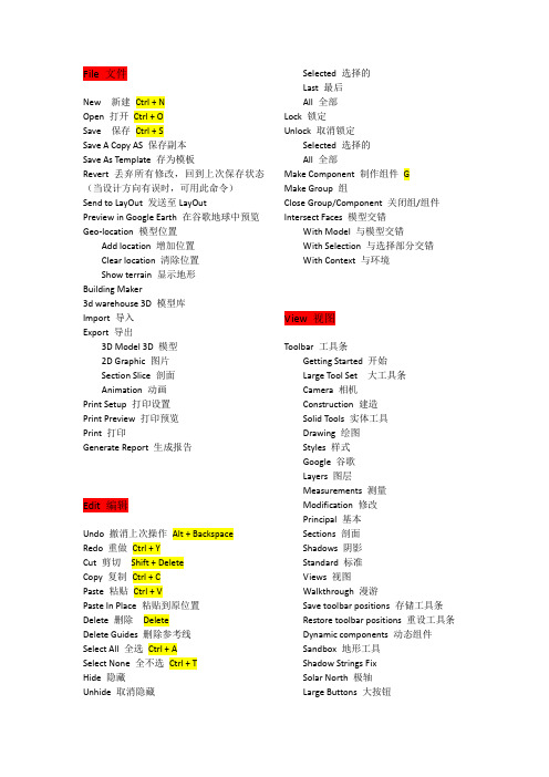
File 文件New 新建Ctrl + NOpen 打开Ctrl + OSave 保存Ctrl + SSave A Copy AS 保存副本Save As Template 存为模板Revert 丢弃所有修改,回到上次保存状态(当设计方向有误时,可用此命令)Send to LayOut 发送至LayOutPreview in Google Earth 在谷歌地球中预览Geo-location 模型位置Add location 增加位置Clear location 清除位置Show terrain 显示地形Building Maker3d warehouse 3D 模型库Import 导入Export 导出3D Model 3D 模型2D Graphic 图片Section Slice 剖面Animation 动画Print Setup 打印设置Print Preview 打印预览Print 打印Generate Report 生成报告Edit 编辑Undo 撤消上次操作Alt + BackspaceRedo 重做Ctrl + YCut 剪切Shift + DeleteCopy 复制Ctrl + CPaste 粘贴Ctrl + VPaste In Place 粘贴到原位置Delete 删除DeleteDelete Guides 删除参考线Select All 全选Ctrl + ASelect None 全不选Ctrl + THide 隐藏Unhide 取消隐藏Selected 选择的Last 最后All 全部Lock 锁定Unlock 取消锁定Selected 选择的All 全部Make Component 制作组件GMake Group 组Close Group/Component 关闭组/组件Intersect Faces 模型交错With Model 与模型交错With Selection 与选择部分交错With Context 与环境View 视图Toolbar 工具条Getting Started 开始Large Tool Set 大工具条Camera 相机Construction 建造Solid Tools 实体工具Drawing 绘图Styles 样式Google 谷歌Layers 图层Measurements 测量Modification 修改Principal 基本Sections 剖面Shadows 阴影Standard 标准Views 视图Walkthrough 漫游Save toolbar positions 存储工具条Restore toolbar positions 重设工具条Dynamic components 动态组件Sandbox 地形工具Shadow Strings FixSolar North 极轴Large Buttons 大按钮Scene tabs 场景标签Hidden geometry 隐藏实体Section planes 剖面Section cutsAxes 轴线Guides 参考线Shadows 阴影Fog 雾化Edge Styles 边线样式Edges 边Back edges 背面边线(透射)KProfiles 轮廓Depth cue 深度变化Extension 延长Face Styles 面样式X-ray X 射线Wireframe 线框Hidden line 隐藏边线Shade 着色Shaded with textures 贴图着色Monochrome 黑白Component Edit 编辑组件Hide rest of model 隐藏模型中编辑组件外的所有内容Hide similar components 隐藏相同组件Animation 动画Add scene 增加场景Update scene 更新场景Delete scene 删除场景Previous scene 前一个场景PageUpNext scene 后一个场景PageDownPlay 播放Settings 设置Camera 相机Previous 前一个相机Next 后一个相机Standard views 标准视图Top 顶视图Bottom 底视图Front 前视图Back 后视图Left 左视图Right 右视图IsoParallel Projection 平行视图Perspective 透视视图Two-Point Perspective 两点透视Match New Photo 照片匹配Edit Matched Photo 编辑匹配的照片Orbit 旋转OPan 平移PZoom 缩放ZField of View 视野Zoom window 缩放至场景至窗口Ctrl + Shift + WZoom extents 缩放选择至窗口Ctrl + Shift + EZoom to photo 缩放至照片Position camera 放置相机Walk 移动相机Look around 环视Image iglloDraw 绘图Line 直线LArc 圆弧AFreehand 自由曲线Rectangle 矩形RCircle 圆CPolygon 多边形Sandbox 地形From contours 从等高线From scratch 从自由绘制网格平面Tools 工具Select 选择SpaceEraser 橡皮EPaint bucket 油漆桶BMove 移动(按下Ctrl可复制,可用*数字表示按这个距离复制多少个,或者/数字表示在这个间距内复制多少个)M Rotate 旋转QScale 缩放SPush/pull 推拉PFollow Me 跟随Offset 偏移FOuter Shell 轮廓Solid tools 实体工具Intersect 交集Union 合集Subtract 抽取Trim 裁剪Split 切割Tape measure 测量TProtractor 量角器Axes 轴线Dimensions 尺寸Text 字3d text 三维字Section plane 剖面Interact 交互Sandbox 地形Smoove 类似于移动……Stamp 图章Drape 褶皱Add detail 增加细节Flip edge 边线反向Window 窗口Model Info 模型信息Entity Info 实体信息Materials 材质Components 组件Styles 样式Layers 图层Outliners 轮廓Scences 场景Shadows 阴影Fog 雾化Match photo 匹配照片Soften edges 边线柔化Instructor 教学指导Preferences 参数设置Hide dialogs 隐藏对话Component options 组件选项Component attributes 组件属性Photo textures 贴图调整右键菜单Entity info 实体信息Erase 删除Hide 隐藏Explode 炸开Select 选择Bounding edges 边界Connected faces 相连面All connected 所有相连All on same layer 同一图层All with same material 同一材质Area 面积Selection 选择Layer 图层Material 材质Make component 制作组件Make group 制作组Intersect faces 交错Reverse faces 反转面的方向Flip along 翻转Red direction 沿红轴方向Green direction 沿绿轴方向Blue direction 沿蓝轴方向Zoom extents 缩放范围Add photo texture 添加照片贴图。
3D英语对照表

file 文件new 新建reset 重置open 打开open recent 打开最近save 保存save as 另存为save copy as 保存副本为save selected 保存选定对象xRef objects.。
外部参照对象xRef Scene.。
. 外部参照场景file link manager 文件链接管理器merge 合并merge animation 合并动画replace 替换import 导入export 导出export selected 导出选定对象archive 存档summary info。
.。
摘要信息file properties。
. 文件属性view image file 查看图像文件exit 退出exit 编辑undo 撒消redo 重做hold 暂存fetch 取回delete 删除clone 克隆select all 全选select none 全部不选select invert 反选select by 选择方式region 区域edit named selection sets 编辑命名选择集object properties 对象属性tools 工具transform Type—In 变换输入selection floater 选择浮动框display floater 显示浮动框layer manager 层管理器light lister 灯光列表mirror 镜像array 阵列align 对齐quick align 快速对齐snapshot 快照spacing tool 间隔工具clone and align 克隆并对齐normal align 法线对齐align camera 对齐摄影机align to view 对齐到视图place highlight 放置高光isolate selection 孤立当前选择rename objects 重命名对象assign vertex colors 指定顶点颜色color clipboard 颜色剪贴板camera match 摄影机匹配grab viewpot 抓取视口measure distance 测量距离channel info 通道信息group 组group 成组ungroup 解组open 打开close 关闭attach 附加detach 分离explode 炸开assembly 集合views 视图undo view change 撒消视图更改redo view change 重做视图更改save active perspective view 保存活动透视视图restore active perspective view 还原活动透视视图grids 栅格viewport background 视口背景update background image 更新背景图像reset background transform 重置背景变换show transform gizmo 显示变换gizmoshow ghosting 显示重影show key times 显示关键点时间shade selected 着色选定对象show dependencies 显示从属关系create camera from view 从视图创建摄影机add default lights to scene 添加默认灯光到场景redraw all views 重画所有视图activate all maps 激活所有视图deactivate all maps 取消激活所有视图update during spnner drag 微调器拖动期间更新adaptive degradation 自适应降级object display culling 对象显示消隐expett mode 专家模式create 创建modifiers 修改器character 角色create character 创建角色destroy character 销毁角色lock 锁定unlock 取消锁定insert character 插入角色save character 保存角色bone tools 骨骼工具set skin pose 设置蒙皮姿势assume skin pose 采用蒙皮姿势akin pose mode 蒙皮姿势模式reactoranimation 动画IK solvers IK解算器constrants 约束transform controllers 变换控制器position controllers 位置控制器rotation controllers 旋转控制器scale controllers 缩放控制器parameter editor 参数编辑器parameter collector 参数收集器wire parameters 关联参数reaction manager 反应管理器make preview 生成预览view preview 查看预览rename preview 重命名预览delete selected animation 删除选定动画graph editors 图表编辑器track view-cunve editor 轨迹视图-曲线编辑器track view-dope sheet 轨迹视图-摄影表new track view 新建轨迹视图delete track view 删除轨迹视图saved track views 保存的轨迹视图new schematic view 新建图解视图delete schematic view 删除图解视图saved schematic views 保存图解视图particle view 粒子视图rendering 渲染render 渲染environment 环境effects 效果advanced lighting 高级照明render to texture 渲染到纹理raytracer setings 光线跟踪器设置raytrace global indude/exdude 光线跟踪全局包含/排除mental ray message window mental ray消息窗口activeshade floater 动态着色浮动框activeshade viewport 动态着色视口material editor 材质编辑器material/map browser 材质贴图浏览器video postshow last rendering 显示上次渲染结果panorama exporter 全景导出器print size wizard 打印大小向导ram player ram播放器customize 自定义customize user interface 自定义用户界面load custom UI scheme 加载自定义UI方案save custom UI scheme 保存自定义UI方案revert to startup layout 还原为启动布局custom UI and defaults switcher 自定义UI与默认设置切换器show UI 显示UIlock UI layout 锁定UI布局configure paths 配置路径units setup 单位设置grid and snap settings 栅格和捕捉设置viewport configuation 视口配置plug-in manager 插件管理器praferences 道德项maxsriptstandard primitives 标准基本体object type 对象类型autogrid 自动栅格box 长方体creation method 创建方法keyboard entry 键盘输入parameters 参数generate mapping 生成贴图坐标cone 圆锥体edge 边center 中心sphere 球体hemisphere 半球chop切除squash 挤压geosphere 几何球体diamete 直径cylinder 圆柱体tube 管状体torus 圆环rotation 旋转twist 扭曲pysamid 四棱锥teapot 茶壶body 壶体handle 壶把spout壶嘴lid 壶盖plane 平面density 密度name and color 名称和颜色extended primitives 扩展基本体hedra 异面体tetra四面体cube/oct立方体,八面体dodec/ico十二面体/二十面体family parameters系列参数axis scaling轴向比率torus kno.。
玛雅命令
Four View——四分图
PerspGraphHyper——透视图形超图形
PerspMultiRender——透视多功能渲染
PerspMultiOutliner——透视多功能轮廓
PerspMulti——透视多功能
PerspOutliner——透视轮廓
Rendering Flags——渲染标记
Hardware Render Buffer——硬件渲染缓冲区
Render View——渲染视图
Shading Groups Editor——阴影组编辑器
Texture View——质地视图
Shading Group Attributes——阴影组属性
Modify——修改
Transformation Tools——变形工具
Move Tool——移动工具
Rotate Tool——旋转工具
Scale Tool——缩放工具
Show Manipulator Tool——显示手动工具
Default Object Manipulator——默认调节器
Hypergraph——超图形
Multilister——多功能渲染控制
Expression Editor——表达式编辑器
Recent Commands——当前命令
Playblast——播放预览
View Arangement——视图安排
Four——四分
3 Top Split——上三分
3 Left Split——左三分
Proportional Modi Tool——比例修改工具
3d 英文对照
3DMAX的中英文对照参数区卷展栏Shader Basic Parameters(着色基本参数区) .Blinn(宾氏).Anisotropic(各向异PPP).metal(金属).Multi-layer(多层式).Phong(方氏).Oren-Nayar-Blinn(表面粗糙的对象).Strauss(具有简单的光影分界线).Wire(线架结构显示模式).2-Sided(双面材质显示).Face Map(将材质赋予对象所有的面).Faceted(将材质以面的形式赋予对象) Blinn Basic Patameters(宾氏基本参数区) .Diffuse(固有色).Ambient(阴影色).Specular(高光色).Self-Illumination(自发光).Opacity(不透明度).Specular Highlights(高光曲线区)..Specular Level(高光级别)..Glossiness(光泽度)..Soften(柔和度)Extended Parameters(扩展参数区) .Falloff(衰减).Filer(过滤法).Subtractive(删减法).Additive(递增法).Index of Refraction(折射率).Wire(线架材质).Reflection Dimming(反射暗淡) SuperSampling(超级样本)Maps(贴图区).Ambient Color(阴影色贴图).Diffuse Color(固有色贴图).Specular Color(高光色贴图).Glossiness(光泽度贴图).Self-Illmination(自发光贴图).Opacity(不透明贴图).Filter Color(过滤色贴图).Bump(凹凸贴图).Reflction(反射贴图).Refraction(折射贴图)..Refract Map/Ray Trace IOR(折射贴图/光线跟踪折射率) .Displacement(置换贴图)Dvnamics Properties(动力学属PPP区)材质类型Blend(混合材质).Material#1(材质#1).Material#2(材质#2).Mask(遮罩).Interactive(交互).Mix Amount(混合数值).Mixing Curve(混合曲线).Use Curve(使用曲线).Transition Zone(交换区域)Composite(合成材质).Composite Bisic Parameters(合成材质基础参数区)..Base Material(基本材质)..Mat.1~Mat.9(材质1~材质9)Double Sided(双面材质).Translucency(半透明) 贴图类型.Facing material(表面材质) Bitmap(位图).Back Material(背面材质) Cellular(细胞)Matte/Shadow(投影材质) Checker(棋盘格).Matte(不可见) Composite(合成贴图).Atmosphere(大气) Dent(凹痕贴图)..Apply Atmosphere(加入大气环境) Falloff(衰减)..At Background Depth(在背景深度) Flat Mirror(镜面反射) ..At Object Depth(在物体深度) Gradient(渐变).Shadow(阴影) Marble(大理石)..Receive Shadow(接受阴影) Madk(罩框)..Shadow Brightness(阴影的亮度) Mix(混合).Reflection(反射) Noise(干扰)Morpher(形态结构贴图) Output(输出)Muti/Sub-Object(多重子物体材质) Partcle Age(粒子寿命) .Set Number(设置数目) Perlin Marble(珍珠岩).Number Of Materials(材质数目) Planet(行星)Raytrace(光线追踪材质) Raytrance(光线跟踪).Shading(明暗) Reflect/Refract(反射/折射).2-Sided(双面) RGB Multiply(RGB倍增).Face Map(面贴图) RGB Tint(RGB染色).Wire(线框) Smoke(烟雾).Super Sample(超级样本) Speckle(斑纹).Ambient(阴影色) Splat(油彩).Diffuse(固有色) Stucco(泥灰).Reflect(反射) Thin Wall Refraction(薄壁折射) .Luminosity(发光度) V ertex Color(项点颜色) .Transparency(透明) Water(水).Index Of Refr(折射率) Wood(木纹).Specular Highlight(反射高光)..Specular Color(高光反射颜色)..Shininess(反射)..Shiness Strength(反光强度).Environment(环境贴图).Bump(凹凸贴图)Shellac(虫漆材质).Base Material(基础材质).Shellac Material(虫漆材质).Shellac Color Blend(虫漆颜色混合) Standard(标准材质)Top/Bottom(项/底材质).Top Material(项材质).Bottom Material(底材质).Swap(置换).Coordinates(坐标轴).Blend(融合).Possition(状态)灯光类型摄像机类型Omni(泛光灯) Target(目标).General Parameters(普通参数) .Lens(镜头尺寸).Projector Parameters(投射贴图) .FOV(视域范围).Attenuation Parameters(衰减参数) .Stock Lenses(镜头类型).Shadow Parameters(阴影参数) .Show Core(显示视域范围).Shadow Map Params(阴影贴图参数) .Show Horizor(显示地平线) Target Spot(目标聚光灯) .Near Range(最近范围)Free SPot(自由聚光灯) .Far Range(最远范围)Target Direct(目标平行光灯)Render Scene(渲染).Rime Output(输出时间)..Single(渲染单帖)..Range(所有帖).Output Size(输出尺寸)Rendering(渲染)/Environment(环境) 粒子系统Background(背景) Spray(喷射)Global Lighting(球形照明) Snow(雪)Atmosphere(大气) Blizzard(暴风雪)Combustion(燃烧) PArray(粒子列阵)V olume Light(体光) Pcloud(粒子云)Fog(雾) Super Spray(超级喷射).Standard(标准).Layered(分层)V olume Fog(体雾)第二部:3DMAX菜单注解一、File(文件)菜单·New(新建):在不改变当前场景系统设置下清除场景中的所有内容。
SceneGraph(场景图)简介
SceneGraph(场景图)简介场景图介绍该节内容翻译⾃gemedev的⼀篇⽂章。
什么是场景图场景图是⼀种将数据排序到层次结构中的⽅法,在层次结构中⽗节点影响⼦节点。
你可能会说“这不是树吗?”你说得没错,场景图就是⼀棵n-tree。
也就是说,它可以有任意多的孩⼦。
但是场景图⽐⼀棵简单的树要复杂⼀些。
它们表⽰在处理⼦对象之前要执⾏的某些操作。
如果现在对这个概念不好理解,不⽤担⼼,这⼀切都会在后⾯的内容中给出解释。
为什么场景图有⽤如果你还没有发现为什么场景图如此酷,那么让我来解释⼀下场景图的⼀些细节。
假设你需要在你的游戏中模拟太阳系。
这个系统⾥⾯,在中⼼有⼀颗恒星,带有两颗⾏星。
每个⾏星也有两颗卫星。
有两种⽅式可以实现这个功能。
我们可以为太阳系中的每个物体创建⼀个复杂的⾏为函数,但是如果设计师想要改变⾏星的位置,那么通过改变所有其他围绕它旋转的物体,就有很多⼯作要做。
另⼀个选择是创建⼀个场景图,让我们的⽣活变得简单。
下图显⽰了如何创建场景图来表⽰对象:假设旋转节点保存当前世界矩阵,并将其与旋转相乘。
这将影响其后渲染的所有其他对象。
所以有了这个场景图,让我们看看这个场景图的逻辑流程。
绘制Star保存当前的矩阵(star)执⾏旋转(star)绘制Planet 1保存当前的矩阵(planet1)执⾏旋转(planet1)绘制Moon A绘制Moon B恢复保存的矩阵(planet1)绘制Planet2保存当前的矩阵(Planet2)执⾏旋转(Planet2)绘制Moon C绘制Moon D恢复保存的矩阵(Planet2)恢复保存的矩阵(star)这是⼀个⾮常简单的场景图的实现,你也应该发现为什么场景图是⼀个值得拥有的东西。
但你可能会对⾃⼰说,这很容易做到,只要硬编码就可以了。
场景图的优势在于场景图的显⽰⽅式可以不通过硬编码的⽅式实现,虽然对于你能想象到的节点,⽐如旋转,渲染等是硬编码实现的。
基于这些知识,我们可以将上⾯的场景变得更加复杂,let's do it。
(完整)3dmax英文翻译(最全的)
编辑器菜单翻译:SELECTION MODIFIERS 选择修改器MESH SELECT 网格选择POLY SELECT 多边形选择PATCH SELECT 面片选择SPLINE SELECT 样条线选择FFD SELECT FFD选择SELECT BY CHANNEL 按通道选择SURFACE SELECT(NSURF SEL) NURBS 曲面选择PATCH/SPLINE EDITING 面片/样条线编辑EDIT PATCH 编辑面片EDIT SPLINE 编辑样条线CROSS SECTION 横截面SURFACE 曲面DELETE PATCH 删除面片DELETE SPLINE 删除样条线LATHE 车削旋转NORMALIZE SPLINE 规格化样条线FILLET/CHAMFER 圆角/切角TRIM/EXTEND 修剪/延伸RENDERABLE SPLINE 可渲染样条线SWEEP 扫描MESH EDITING 网格编辑DELETE MESH 删除网格EDIT MESH 编辑网格EDIT POLY 编辑多边形EXTRUDE 挤出FACE EXTRUDE 面挤出NORMAL 法线SMOOTH 平滑BEVEL 倒角、斜切BEVEL PROFILE 倒角剖面TESSELLATE 细化STL CHECK STL检查CAP HOLES 补洞VERTEXPAINT 顶点绘制OPTIMIZE 优化MULTIRES 多分辨率VERTEX WELD 顶点焊接SYMMETRY 对称EDIT NORMALS 编辑法线EDITABLE POLY 可编辑多边形EDIT GEOMETRY 编辑几何体SUBDIVISION SURFACE 细分曲面SUBDIVISION DISPLACEMENT 细分置换PAINT DEFORMATION 绘制变形CONVERSION 转化TURN TO PATCH 转换为面片TURN TO MESH 转换为网格ANIMATION MODIFIERS 动画EDIT ENVELOPE 编辑封套WEIGHT PROPERTIES 权重属性MIRROR PARAMETERS 镜像参数DISPLAY 显示ADVANCED PARAMETERS 高级参数GIZMO 变形器MORPHER 变形器CHANNEL COLOR LEGEND 通道颜色图例GLOBAL PARAMETERS 全局参数CHANNEL LIST 通道列表CHANNEL PARAMETERS 通道参数ADVANCED PARAMETERS 高级参数FLEX 柔体PARAMETERS 参数SIMPLE SOFT BODIES 简章软体WEIGHTS AND PAINTING 权重和绘制FORCES AND DEFLECTORS 力和导向器ADVANCED PARAMETERS 高级参数ADVANCED SPRINGS 高级弹力线MELT 融化LINKED XFORM 链接变换PATCH DEFORM 面片变形PATH DEFORM 路径变形SURF DEFORM 曲面变形PATCH DEFORM(WSM) 面片变形(WSM)PATH DEFORM(WSM) 路径变形(WSM)SURF DEFORM(WSM)曲面变形(WSM)SKIN MORPH 蒙皮变形SKIN WRAP 蒙皮包裹SKIN WRAP PATCH 蒙皮包裹面片SPLINE IK CONTROL 样条线IK控制ATTRIBUTE HOLDER 属性承载器UV COORDINATES MODIFIERS UV坐标修改器UVW MAP UVW贴图UNWRAP UVW 展开UVWUVW XFORM UVW变换MAPSCALER(WSM)贴图缩放器(WSM) MAPSCALER 贴图缩放器(OSM)CAMERA MAP 摄影机贴图CAMERA MAP(WSM)摄影机贴图(WSM)SURFACE MAPPER(WSM)曲面贴图(WSM)PROJECTION 投影UVW MAPPING ADD UVW贴图添加UVW MAPPING CLEAR UVW贴图清除POINT CACHE 点缓存POINT CACHE(WSM)点缓存(WSM)SUBDIVISION SURFACES 细分曲面TURBOSMOOTH 涡轮平滑MESHSMOOTH 网格平滑HSDS MODIFIER HSDS修改器FREE FORM DEFORMATIONS 自由形式变形FFD MODIFIERS FFD修改FFD BOX/CYLINDER FFD长方形/圆柱体PARAMETRIC MODIFIERS 参数化修改器BEND 弯曲TAPER 锥化TWIST 扭曲NOISE 噪波STRETCH 拉伸、伸展SQUEEZE 挤压PUSH 推力RELAX 松弛RIPPLE 涟漪WAVE 波浪SKEW 倾斜ALICE 切片SPHERIFY 球形化AFFECT REGION 影响区域LATTICE 晶格MIRROR 镜像DISPLACE 置换XFORM 变换SUBSTITUTE 替换PRESERVE 保留SHELL 壳SURFACE 曲面MATERIAL 材质MATERIAL BY ELEMENT 按元素分配材质DISP APPROX 置换近似DISPLACE MESH(WSM)置换网格(WSM)DISPLACE NURBS(WSM)置换网格(WSM)RADIOSITY MODIFIERS 沟通传递修改器SUBDIVIDE(WSM)细分(WSM)SUBDIVIDE 细分材质编辑器:Reglection(反射)Basic Parameters(基本参数) Refraction(折射)。
3Dmax中英文详细翻译对照
3Dmax中英文对照参考软件:3Dmax8中文版+vray1.5中文版和3Dmax8英文版+vray1.5英文由于任务繁重,有些相同的内容只写一遍,还望谅解。
如有重复纯属糊涂and巧了。
一、右击菜单(由于有些右击菜单中在修改卷栏中也有在这就不复述)(右击菜单左侧)(右击菜单右侧)反转样条线: Reverse Line 孤立当前选择: Isolate selection设为首顶点: make first 全部解冻: unfreeze all拆分: divide 冻结当前选择: freeze selection绑定: bind 按名称取消隐藏: unhide by name取消绑定: Unbind 全部取消隐藏: unhide all 工具 1: tools 1 隐藏未选定对象: hide unselection 工具 2: tools 2 隐藏当前选择: hide selection 创建线: create line 保存场景状态: save scene state 附加: attach 管理场景状态: mange scene states 分离线段: detach segment 显示: display连接: connect 变换: transform 细化: refine 移动: move细化连接: connect refine 旋转: rotate循环顶点: cycle vertices 缩放: scale断开顶点: break vertices 选择: select焊接顶点: weld vertices 克隆: clone融合顶点: fuse vertices 属性: propertiesBezier角点: Bezier corner 曲线编辑器: curve editorBezier : bezier 摄影表: dope sheet角点: corner 关联参数: wire parameters平滑: smooth 转换为: convert to重置切线: reset tangents (展开)可编辑样条线: convert to editorspline样条线: spline 可编辑网络: convert to editormesh线段: segment 可编辑多边形: convert to editor poly顶点: vertex 可编辑片面: convert to editorpatch顶层级: top-level 转换为 NURBS: convert to NURBS线: line VRAY 属性: VRAY porperties曲线: curve VRAY场景转换器: VRAY scene converterVRAY网格导出: VRAY mesh export VRAY VFB : VRAY VFB二、修改器:mordifiers选择: selectionFFD 选择:fFFD select网格选择:mesh select面片选择:patch select多边形选择:poly select按通道选择:select by channel样条线选择:spline select体积选择:volume select面片/样条线编辑:patch/spline editing横截面:cross section删除面片:delete patch删除样条线:delete spline编辑面片:edit patch编辑样条线:edit spline圆角/切角:fillet/chamfer车削:lathe规格化样条线:normalize spline可渲染样条线修改器:renderable spline modifier曲面:surface扫描:sweep修剪/延伸:trim/extend网格编辑: mesh补洞:cap holes删除网格:delete mesh编辑网格:edit mesh编辑法线:edit normals编辑多边形:edit poly挤出:extrude面挤出:face extrudemultires:multires法线修改器:normal modifier优化:optimize平滑:smoothSTL检查:STL check对称:symmetry细化:fessellate顶点绘制:vertex paint顶点焊接:vertex weld动画:animation属性承载器:attribute holder 柔体:flex链接变换:linked xform融化:melt变形器:morpher面片变形:patch deform面片变形(WSM):patch deform(WSM)路径变形:path deform路径变形(WSM):patch deform(WSM)蒙皮:skin蒙皮变形:skin morph蒙皮包裹:skin wrap蒙皮包裹面片:skin wrap patch样条线 IK 控制:spline IK control曲面变形:surf deform曲面变形(WSM):surf deform(WSM)UV坐标:UV coordinates摄影机贴图:camera map摄影机贴图(WSM):camera map(WSM)贴图缩放器(SWM):map scaler(WSM)投影:projection展开UVW:unwrap UVWUVW贴图:UVW mapUVW贴图添加:UVW mapping AddUVW贴图清楚:UVW mapping clearUVW贴图变换:UVW mapping XForm缓存工具:cache tools点缓存:point cache点缓存(WSM):point cache(WSM)细分曲面:subdivision surfacesHSDS修改器:HSDSmordifier网络平滑:网格平滑:mesh smooth涡轮平滑:turbo smooth自由形式变形器:free form deformersFFD长方体:FFDBOXFFD圆柱体:FFD cylinder参数变形器:parametric deformers影响区域:affect region弯曲:bend置换:displace晶格:lattice镜像:mirror噪波:noisePhysique:physique推力:push保留:preserve松弛:relax涟漪:ripple壳:shell切片:slice拉伸:stretch球形化:spherify挤压:squeeze扭曲:twist推化:taper替换:XForm波浪:wave曲面:surface置换近似:disp approx置换网格:displace mesh材质:material按元素分配材质:material by elementNURBS编辑:NURBS editing置换近似:disp approx曲面变形:surf deform曲面选择:surface select光能传递:radiosity细分:subdivide细分(WSM):sudiosity(WSM)三、可编辑样条线修改器菜单渲染:rendering在渲染中启用:enable in renderer在视口中启用:enable in viewport生成贴图坐标:senerat mapping coords真实世界贴图大小:real-world map size视口:viewport径向:radial厚度:thichness边:sides角度:angle纵横比:aspect自动平滑:auto smooth阈值:threshold插值:interpolation步数:steps自适度:adaptive名称选择:named selections复制:copy粘贴:paste锁定控制柄:lock handles相似:alike区域选择:area selection线段端点:segment end选择方式:select by。
3dsmax中英文对照大全
3dsmax中英文对照大全一、File〈文件〉New〈新建〉Reset〈重置〉Open〈打开〉Save〈保存〉Save As〈保存为〉Save selected〈保存选择〉XRef Objects〈外部引用物体〉XRef Scenes〈外部引用场景〉Merge〈合并〉Merge Animation〈合并动画动作〉Replace〈替换〉Import〈输入〉Export〈输出〉Export Selected〈选择输出〉Archive〈存档〉Summary Info〈摘要信息〉File Properties〈文件属性〉View Image File〈显示图像文件〉History〈历史〉Exit〈退出〉二、Edit〈菜单〉Undo or Redo〈取消/重做〉Hold and fetch〈保留/引用〉Delete〈删除〉Clone〈克隆〉Select All〈全部选择〉Select None〈空出选择〉Select Invert〈反向选择〉Select By〈参考选择〉Color〈颜色选择〉Name〈名字选择〉Rectangular Region〈矩形选择〉Circular Region〈圆形选择〉Fabce Region〈连点选择〉Lasso Region〈套索选择〉Region:〈区域选择〉Window〈包含〉Crossing〈相交〉Named Selection Sets〈命名选择集〉Object Properties〈物体属性〉三、Tools〈工具〉Transform Type-In〈键盘输入变换〉Display Floater〈视窗显示浮动对话框〉Selection Floater〈选择器浮动对话框〉Light Lister〈灯光列表〉Mirror〈镜像物体〉Array〈阵列〉Align〈对齐〉Snapshot〈快照〉Spacing Tool〈间距分布工具〉Normal Align〈法线对齐〉Align Camera〈相机对齐〉Align to View〈视窗对齐〉Place Highlight〈放置高光〉Isolate Selection〈隔离选择〉Rename Objects〈物体更名〉四、Group〈群组〉Group〈群组〉Ungroup〈撤消群组〉Open〈开放组〉Close〈关闭组〉Attach〈配属〉Detach〈分离〉Explode〈分散组〉五、Views〈查看〉Undo View Change/Redo View change〈取消/重做视窗变化〉Save Active View/Restore Active View〈保存/还原当前视窗〉Viewport Configuration〈视窗配置〉Grids〈栅格〉Show Home Grid〈显示栅格命令〉Activate Home Grid〈活跃原始栅格命令〉Activate Grid Object〈活跃栅格物体命令〉Activate Grid to View〈栅格及视窗对齐命令〉Viewport Background〈视窗背景〉Update Background Image〈更新背景〉Reset Background Transform〈重置背景变换〉Show Transform Gizmo〈显示变换坐标系〉Show Ghosting〈显示重橡〉Show Key Times〈显示时间键〉Shade Selected〈选择亮显〉Show Dependencies〈显示关联物体〉Match Camera to View〈相机与视窗匹配〉Add Default Lights To Scene〈增加场景缺省灯光〉Redraw All Views〈重画所有视窗〉Activate All Maps〈显示所有贴图〉Deactivate All Maps〈关闭显示所有贴图〉Update During Spinner Drag〈微调时实时显示〉Adaptive Degradation Toggle〈绑定适应消隐〉Expert Mode〈专家模式〉六、Create〈创建〉Standard Primitives〈标准图元〉Box〈立方体〉Cone〈圆锥体〉Sphere〈球体〉GeoSphere〈三角面片球体〉Cylinder〈圆柱体〉Tube〈管状体〉Torus〈圆环体〉Pyramid〈角锥体〉Plane〈平面〉Teapot〈茶壶〉Extended Primitives〈扩展图元〉Hedra〈多面体〉Torus Knot〈环面纽结体〉Chamfer Box〈斜切立方体〉Chamfer Cylinder〈斜切圆柱体〉Oil Tank〈桶状体〉Capsule〈角囊体〉Spindle〈纺锤体〉L-Extrusion〈L形体按钮〉Gengon〈导角棱柱〉C-Extrusion〈C形体按钮〉RingWave〈环状波〉Hose〈软管体〉Prism〈三棱柱〉Shapes〈形状〉Line〈线条〉Text〈文字〉Arc〈弧〉Circle〈圆〉Donut〈圆环〉Ellipse〈椭圆〉Helix〈螺旋线〉NGon〈多边形〉Rectangle〈矩形〉Section〈截面〉Star〈星型〉Lights〈灯光〉Target Spotlight〈目标聚光灯〉Free Spotlight〈自由聚光灯〉Target Directional Light〈目标平行光〉Directional Light〈平行光〉Omni Light〈泛光灯〉Skylight〈天光〉Target Point Light〈目标指向点光源〉Free Point Light〈自由点光源〉Target Area Light〈指向面光源〉IES Sky〈IES天光〉IES Sun〈IES阳光〉SuNLIGHT System and Daylight〈太阳光及日光系统〉Camera〈相机〉Free Camera〈自由相机〉Target Camera〈目标相机〉Particles〈粒子系统〉Blizzard〈暴风雪系统〉PArray〈粒子阵列系统〉PCloud〈粒子云系统〉Snow〈雪花系统〉Spray〈喷溅系统〉Super Spray〈超级喷射系统〉七、Modifiers〈修改器〉Selection Modifiers〈选择修改器〉Mesh Select〈网格选择修改器〉Poly Select〈多边形选择修改器〉Patch Select〈面片选择修改器〉Spline Select〈样条选择修改器〉Volume Select〈体积选择修改器〉FFD Select〈自由变形选择修改器〉NURBS Surface Select〈NURBS表面选择修改器〉Patch/Spline Editing〈面片/样条线修改器〉:Edit Patch〈面片修改器〉Edit Spline〈样条线修改器〉Cross Section〈截面相交修改器〉Surface〈表面生成修改器〉Delete Patch〈删除面片修改器〉Delete Spline〈删除样条线修改器〉Lathe〈车床修改器〉Normalize Spline〈规格化样条线修改器〉Fillet/Chamfer〈圆切及斜切修改器〉Trim/Extend〈修剪及延伸修改器〉Mesh Editing〈表面编辑〉Cap Holes〈顶端洞口编辑器〉Delete Mesh〈编辑网格物体编辑器〉Edit Normals〈编辑法线编辑器〉Extrude〈挤压编辑器〉Face Extrude〈面拉伸编辑器〉Normal〈法线编辑器〉Optimize〈优化编辑器〉Smooth〈平滑编辑器〉STL Check〈STL检查编辑器〉Symmetry〈对称编辑器〉Tessellate〈镶嵌编辑器〉Vertex Paint〈顶点着色编辑器〉Vertex Weld〈顶点焊接编辑器〉Animation Modifiers〈动画编辑器〉Skin〈皮肤编辑器〉Morpher〈变体编辑器〉Flex〈伸缩编辑器〉Melt〈熔化编辑器〉Linked XForm〈连结参考变换编辑器〉Patch Deform〈面片变形编辑器〉Path Deform〈路径变形编辑器〉Surf Deform〈表面变形编辑器〉*Surf Deform〈空间变形编辑器〉UV Coordinates〈贴图轴坐标系〉UVW Map〈UVW贴图编辑器〉UVW Xform〈UVW贴图参考变换编辑器〉Unwrap UVW〈展开贴图编辑器〉Camera Map〈相机贴图编辑器〉*Camera Map〈环境相机贴图编辑器〉Cache Tools〈捕捉工具〉Point Cache〈点捕捉编辑器〉Subdivision Surfaces〈表面细分〉MeshSmooth〈表面平滑编辑器〉HSDS Modifier〈分级细分编辑器〉Free Form Deformers〈自由变形工具〉FFD2×2×2/FFD3×3×3/FFD4×4×4〈自由变形工具2×2×2/3×3×3/4×4×4〉FFD Box/FFD Cylinder〈盒体和圆柱体自由变形工具〉Parametric Deformers〈参数变形工具〉Bend〈弯曲〉Taper〈锥形化〉Twist〈扭曲〉Noise〈噪声〉Stretch〈缩放〉Squeeze〈压榨〉Push〈推挤〉Relax〈松弛〉Ripple〈波纹〉Wave〈波浪〉Skew〈倾斜〉Slice〈切片〉Spherify〈球形扭曲〉Affect Region〈面域影响〉Lattice〈栅格〉Mirror〈镜像〉Displace〈置换〉XForm〈参考变换〉Preserve〈保持〉Surface〈表面编辑〉Material〈材质变换〉Material By Element〈元素材质变换〉Disp Approx〈近似表面替换〉NURBS Editing〈NURBS面编辑〉NURBS Surface Select〈NURBS表面选择〉Surf Deform〈表面变形编辑器〉Disp Approx〈近似表面替换〉Radiosity Modifiers〈光能传递修改器〉Subdivide〈细分〉*Subdivide〈超级细分〉八、Character〈角色人物〉Create Character〈创建角色〉Destroy Character〈删除角色〉Lock/Unlock〈锁住与解锁〉Insert Character〈插入角色〉Save Character〈保存角色〉Bone Tools〈骨骼工具〉Set Skin Pose〈调整皮肤姿势〉Assume Skin Pose〈还原姿势〉Skin Pose Mode〈表面姿势模式〉九、Animation〈动画〉IK Solvers〈反向动力学〉HI Solver〈非历史性控制器〉HD Solver〈历史性控制器〉IK Limb Solver〈反向动力学肢体控制器〉SplineIK Solver〈样条反向动力控制器〉Constraints〈约束〉Attachment Constraint〈附件约束〉Surface Constraint〈表面约束〉Path Constraint〈路径约束〉Position Constraint〈位置约束〉Link Constraint〈连结约束〉LookAt Constraint〈视觉跟随约束〉Orientation Constraint〈方位约束〉Transform Constraint〈变换控制〉Link Constraint〈连接约束〉Position/Rotation/Scale〈PRS控制器〉Transform Script〈变换控制脚本〉Position Controllers〈位置控制器〉Audio〈音频控制器〉Bezier〈贝塞尔曲线控制器〉Expression〈表达式控制器〉Linear〈线性控制器〉Motion Capture〈动作捕捉〉Noise〈燥波控制器〉Quatermion(TCB)〈TCB控制器〉Reactor〈反应器〉Spring〈弹力控制器〉Script〈脚本控制器〉XYZ〈XYZ位置控制器〉Attachment Constraint〈附件约束〉Path Constraint〈路径约束〉Position Constraint〈位置约束〉Surface Constraint〈表面约束〉Rotation Controllers〈旋转控制器〉注:该命令工十一个子菜单。
- 1、下载文档前请自行甄别文档内容的完整性,平台不提供额外的编辑、内容补充、找答案等附加服务。
- 2、"仅部分预览"的文档,不可在线预览部分如存在完整性等问题,可反馈申请退款(可完整预览的文档不适用该条件!)。
- 3、如文档侵犯您的权益,请联系客服反馈,我们会尽快为您处理(人工客服工作时间:9:00-18:30)。
Projective Image WarpingAs suggested by its name,image based rendering is concerned with creating new images from old ones.Recently there have been lots of descriptions of novel representations,such as light-fields, and the warping of depth images to produce3d like parallax effects.But the basic idea of using old images to make new ones is quite old.In particular the use of texture mapping takes input image data(the texture),places it in some virtual3d world,and views it(texture mapping)on the image plane.The original texture image is warped onto the new image plane using what is called a projective warp.In this section we will discuss a simple family of warps called projective warps.These warps do not use any sort of depth or opticalflow information.Warps that use depth andflow will be discussed in detail later in the course.We will demonstrate two powerful ideas.First that if one views a planar object using two(or more)pin hole cameras,then those two images are related by a projective warp;ie.if we apply the warp to thefirst image,we obtain the second image. This result is at the core of texture mapping.In texture mapping,we use one image,the texture, to represent the photometric appearance of a(nearly)planar object,and this is viewed from an arbitrary viewpoint to create a second image.The second idea about projective warps we will demonstrate is that if one creates two(or more)images from a single center of projection(the camera only rotates,and changes its intrinsic properties,such as its zoom),then those two images are related by a projective warp.This result is at the core of environment mapping and panoramic images.If one takes a number of pictures from a single point of view,one can stitch this panorama of images together using a projective warp. From this data one can simulate a new view from the same center of projection by applying the projective warp.In this section we will discuss two types of applications and benefits of simple warps.These two types applications run through the core of most IBR work.First image warping lets us use photographs of real world scenes in an interactive graphics setting.Second,image warping is fast, and can allow us to render imagery faster than other techniques.First,simple image warping allows us to easily model complicated real world appearances that may be difficult to model manually.By using a photograph as a texture,one effectively captures real world photometric information,and places it in a virtual environment.Projective warps know nothing about the depths of objects in the world,and so they can be applied to real photographs without any sort of active scanning techniques or vision-type analysis.We discuss texture mapping and how it is a simple example of a projective image transform.We discuss environment maps and image panoramas which give a simple description of the world as seen looking out from a single point.These panoramas offer a simple way to photographically capture interesting real world environments in which to place a virtual user.The second benefit of simple warps is fast rendering.Image warping involves simple and regular computation.It can therefore be computed very efficiently,especially with the use of hardware.Texture mapping is useful,even if the texture is generated by a computer,and not from a photograph.This efficiency of image warping is used to render complicated appearance, (even synthetically modeled appearance)more quickly than if we were to use simpler rendering techniques,such as smoothly shaded polygon rendering.These simple types of warps can also be used to speed up the rendering of purely synthetic en-vironments.In typical virtual settings,as the user or objects move around,many parts of the imagestay the same,or perhaps warp in simple ways.V arious rendering systems have been designed to make use of this temporal coherence by essentially“reusing”various image regions.These system rely on similar types of image warps seen in texture mapping and environment mapping.In this section we will discuss these systems as well.Finally,to draw the connection between projective warping,and image based methods that use depth information,we will discuss the relationship between these warping methods and the warping methods that have motion or depth information associated with the pixels.Basics:Projective MapsA projective map is a mapping that maps from one image coordinate system x i1y i1to another image coordinate system x i2y i2.It is computed multiplying thefirst coordinates by a3by3 matrix,and dividing out by r.x i2r y i2rr m1m2m3m4m5m6m7m8m9x i1y i11Explicitly this can be written out asx i2m1x i1m2y i1m3m7x i1m8y i1m9Note that if we multiply the whole matrix by a scale factor,we will get the same transformation, and so there are really eight degrees of freedom specifying the map.In general during texture mapping,the mapping from texture coordinates to the new image is a projective transformation.There is a special simple subfamily of projective maps that come from matrices with a bottom row of001called affine maps.x i2 y i2 1m1m2m3m4m5m6001x i1y i11Affine maps can translate,scale,skew,and rotate2d images.A full projective map can do fancier things,like make parallel lines converge to a point.This is necessary to get effects like foreshortening.Affine maps can be computed a bit quicker than projective maps,because no division is required.Basics:Pin hole camerasIn graphics we take the three dimensional world,and project it down to a two dimensional image using a pin-hole camera model.This is described using matrix operations.Computer graphics practitioners like to have an image space z value after projection,in order to compute the visible surface,so they tend to use four by four matrices.During rendering,somepoint in space x g y g z g,perhaps some polygon vertex is mapped to“image coordinates”x i y i z i using the four by four matrix C.x i w iy i w i z i w i w i Cx gy gz g1The four by four matrix C V F E can be considered a composition of three matrices.E is a Euclidian transform expressing a rotation and a translationE r11r12r13t1 r21r22r23t1 r31r32r33t1 0001F expresses the projection using a camera frustum projection.And V,a viewport transformation maps us to pixel coordinates.In order to extract the actual image coordinates,one needs to divide out the w i coordinate.Computer vision practitioners tend to describe real cameras,that don’t keep around any z val-ues,and as such they tend to describe the imaging process asx i w iy i w i w i Px gy gz g1P A N E is a3by4matrix,composed of the following parts.The position and orientation of the camera is determined by E.The canonical camera projection is described byN 1000 0100 0001And the intrinsic camera parameters are defined by the three by three upper diagonal matrix matrixA f s xθt x 0f s y t y 001Where f is the focal length,s x s y are horizontal and vertical pixel scales,t x t y positions the focal center,andθallows for skewed,non-rectangular pixels.Texture MappingIn this section we briefly visit the topic of texture mapping and describe how it is an application of a projective mapping operation.Texture mapping is a process where we place some interesting looking pattern onto a polygon in space.This pattern may be computer generated,hand drawn,or be a photograph.The pattern is represented as an image made up of pixels called texels.During the rendering process,these texels are conceptually mapped onto the polygon and then viewed through the pin hole camera and viewed on the screen.This can be expressed in matrices as[1]x i w iy i w i w i P3x4G4x3T3x3x ty t1The3by3T matrix scales and translates and rotates the texture to put it on the two dimensional polygon;this is an affine map.The4by3matrix G takes the two dimensional polygon and puts it into3d space.This is also an affine map.The3by4matrix P is the pin hole projection that maps the3d geometry onto the image plane.The concatenation of these three matrices is a three by three matrix M P G T.This matrix represents the transformation from texture space to image space. Thus texture mapping is a projective map from texture space to image space using a3by3matrix M.In a real graphics language,such as openGL,one does not specify M directly.P is specified by the camera commands.M is specified by the placement of the polygon in the world.T is specified by specifying texture coordinates x t y t at the three vertices of a triangle.The above mapping describes the map from texture to image.Typically,in a texture mapping implementation,we in fact use the inverse map,that maps from image domain to texture domain. For each image pixel location x i y i,we compute the mapped texture location,and then the proper color value is interpolated.Texture mapping can be implemented quite efficiently.During the rendering,as the renderer moves across a scan line,the matrix multiply can be evaluated incrementally with a few add oper-ations,and the division by the third coordinate.Two views of a planar objectIn this section we show how two views of a planar object,such as the facade of a building,are related by a projective map.If I take a picture of a facade,and wish to view it from a different position in space,I can create the new view by applying a projective map to thefirst image.Suppose one takes a picture of a planar object,and without loss of generality lets assume that the plane is defined by z g0,then the image of the planar points in camera1arex i1w i1y i1w i1 w i1P1x gy g1By dropping the third column of P1,we can obtain a three by three matrix M1that maps points on the planar object to the image plane.x i1w i1y i1w i1 w i1M1x gy g1Suppose the same plane is viewed from a second camera in a different location,apply the same reasoning to obtainx i2w i2y i2w i2 w i2M2x gy g1Assuming the M matrices are invertible,we obtainx i1w i1y i1w i1 w i1M1M12x i2w i2y i2w i2w i2Dividing both sides by w i2gives usx i1ry i1r r M1M12x i2y i21Hence we see that one can map the view of a planar object from one camera to another camera,simply by multiplying thefirst image coordinates by a three by three matrix,and dividing throughby r.Returning to our simple example,If I take a picture of a facade,and wish to view it from adifferent position in space,I can create the new view by applying a projective map to thefirst image.This can be thought of as essentially a texture mapping operation.One models the3dgeometry of the planar facade,one specifies that the texture should be mapped onto that plane,andthen one views it from a some virtual camera.But the situation is slightly trickier.In simple texturemapping M P G T,the T matrix representing the mapping of the texture onto the geometry,was assumed to be an affine map.This mapping was specified by specifying the x t y t texture coordinates at3vertices of a triangle.This affine does not allow for perspective effects in theoriginal texture.In our case here,the texture itself is a photograph with pin hole perspective.Wereally need the ability to specify a general projective transform for T.OpenGL allows us to do thisin two different ways.Thefirst way is to directly manipulate the so called texture matrix stack.The other way is to pass three texture coordinates x t q y t q q per triangle vertex instead of two. This q essentially accounts for the divide of the mapping M2,and so it should be set to w i2Environment Mapping and PanoramasAnother quite similar technique to texture mapping is environment mapping.The basic idea of en-vironment mapping is that as I look out into my environment from some single center of projection point,I can measure what is seen in each direction,and represent that in some appropriate data structure.This data structure organizes the data sampled at the various directions.Examples for the organizing data structures include cubes,spheres,and cylinders.Graphics systems have used environments maps as ways of simply representing the distant part of the world,either for direct viewing,or for approximate reflection computation.More recently, people have been interested in capturing environment maps photographically,and then using this data to place a user in a virtual version of a real world environment.The types of projections that let us do texture mapping,also allow us to do environment map-ping.If I take a camera and move it back and forth,parallax occurs and certain objects can occlude one another.But when I take a camera and rotate it around its center of projection,this cannot occur.All I can see in these cameras is what can be seen by the pencil of rays that meet at the center of projection.This suggests that there should be a way to map the pixels in one view to pixels in the other.This is in fact true,and can be achieved by a projective transformation.We can see this with an argument similar to the one used for planar objectsSuppose one has a single camera,and without loss of generality,lets us place it at the origin, then the image of the scene points in camera1arex i1w i1y i1w i1w i1A1N R1001x gy gz g1A1R1x gy gz gwhere R1is the3by3matrix describing the rotation of thefirst camera.Hence the mapping from world coordinates to camera1coordinates is described by a simple3by3matrix A1R1 If we have a second camera with the same center of projection,namely the origin,then the mapping from world to camera2coordinates is also described by a3by3matrix A2R2.As a result,one can map from image2coordinates to image1coordinates by multiplying by the3by3 matrix A1R1R12A12,and dividing by the homogeneous coordinate.Hence we conclude two views of a scene from a single center of projection are related by a projective transformation.Image MosaicsImage mosaics and panoramic images are based on the idea that all images that share a center of projection can be easily warped to each other’s coordinate systems.A user takes multiple pictures from a common point.These images are then warped into a common coorditate system.This represents a widefield of view,or perhaps a full surround view from this point.New planar images can be construced from this representation.Here we sketch the basic steps in creating a planar image mosaic.Step1:take multiple pictures from a single center of projection.If one wants to be very careful about this,one should use a tripod.As one spins the camera,one should check to see that there is no parallax(occlusion changes)occurring.If there is parallax,one must adjust the camera on the tripod so that it rotates about a different point.Step2:Pick a single image to the be the reference view.All of the other images will be mapped to this view.Step3:For each other image,I,determine the projective transform that maps I to the reference view coordinate system.This transform will make the overlapping parts of the two images align perfectly.There are a few ways this transform could be computed.If the user marks four corre-sponding points in the reference image,and in I,then one can directly solve for the appropriate matrix.Another method is to use numerical optimization tofind the correct matrix[9].Essen-tially one solves for the matrix such that after warping,the region of the I,that overlaps with the reference image is as similar as possible.If an image does not contain significant overlapping data with the reference view,then we cannot directly compute the required projective transform.But this is not a problem.As long as Ihas overlap with an image J,and we know the correct transformation from J to the reference view, then we can compute the transform from I’s coordinate system to J’s,and compose that with the transform from J to the reference view.step4:Warp all images to the reference view’s coordinate system.Resampling will be neces-sary since the warped sample locations will not generally lie on integer values.PanoramasThere are a few limitations to the image mosaicing approach outlined above.First it artificially picks a single view to be the reference coordinate system.Secondly a single image coordinate system can at best represent a180degreefield of view.Thirdly,in a typical example,the images are gathered by rotating a camera around a single axis,and so there is really only one unknow degree of freedom specifying the relationship between any two images,not eight.To solve for the limitedfield of view,global data structures,such as a cylinder,sphere,or cube can be used to represent the view of the world from a single point.If one knows the intrinsic and extrinsic camera parameters for each image(ie.the P matrix),then one knows the mapping between pixels in the image,and rays in the world,and can easily map them onto the global data structure.If one does not know this information,then one must solve this information from the given views.Details of how to do this are described for example in[5]and[8].In these algorithms, assumptions are made on the real degrees of freedom,such as that the camera does not change its intrinsic parameters as the pictures are taken,and that it may only be rotating about the y axis. Image reuse for fast renderingImage warping techniques are used not only to capture“real”world environments,but also to speed up the rendering of synthetic scenes.During many rendering sequences,subsequent frames can be quite similar.As a user translates,distant objects don’t appear to move at all.As a user rotates,distant objects move simply across the screen with almost no parallax effects.A number of rendering algorithms have been developed that take advantage of this coherence by reusing image regions over a series of frames.When a frame is generated,some parts of the scene are rendered simply by warping the associated pixels from the previous frame.Parts of the image where the visual changes are dramatic are rerendered directly from the geometry.There are a variety of issues in determining which scene elements to image warp,and which ones to redraw from geometry.There are also issues determining what is the best warp to use for the reused regions.Shade et al.[6]describe a system for accelerating walkthroughs of complex environments.In their system,the objects in the environment are organized into a spatial BSP tree.Each BSP tree leaf node contains an object,and the internal nodes hierarchically contain collections of objects. When thefirst frame of a sequence is rendered all of the objects are rendered from their geometry. Each of these images is stored as an“image cache”.They also store image caches for the hierarchy of object collections corresponding to the internal BSP tree nodes.When the user moves,the BSP tree of the scene is traversed to rerender the scene.For each node,an error criteria is checked to see if the corresponding image cache can be reused.To reuse the image cache,it is used as a texture that is mapped on to a planar billboard in space.Their error metric approximates the discrepancy between the correct rerendered object and the appearance ofthe texture mapped billboard.If the error of using the image cache is too high,then the object is rendered by recursively calling the algorithm on the BSP children of this node.When a BSP leafs fail the error measure,then the appropriate geometry is rerendered.In effect what happens is that nearby objects get rerenderd from the geometry almost at every frame.As we consider objects further away from the viewer,they get rerendered less often,and their billboards are just rendered as texture maps.At very far distances,large clusters of objects are rerendered as a single textured billboard.The Talisman rendering architecture[10]is a hardware rendering architecture based on the concept of image reuse.The hardware has a standard polygon renderer that renders each object into its own sprite.Another component of the hardware takes sprites,applies an arbitrary affine warp to it,and composites it onto the image screen.As a geometric objects move about a scene, its sprite can be affinely warped(ex.scaled and translated)to approximate the appearance of the proper motion.If the affine transform is a poor approximation to the proper appearance of the object,its sprite can be updated,by rerendering it in the rendering hardware component.In Talisman,these two hardware components,the renderer and the warper,are decoupled.The warper runs at frame rate,and must warp and composite each sprite per frame.The renderer up-dates sprites when requested,and does so as fast as it can.A controlling program decides which sprites are invalid in each frame must be rendered,typically,only a fraction of the sprites are up-dated in a frame.The controlling program also decides what is the best affine warp to use,and and passes that information onto the warping engine.Lengyel and Snyder[3]describe the systematic way in which such a program can decide on the best affine warp.They also perform a compari-son between using affine warps,and the full power of a projective transform.Their experiments find that the full projective transform does not add a significant advantage over affine transforms. Affine transforms are much cheaper to implement,since they require no divide operations. Warping with depthIn subsequent sections of this course,we will see uses of warping that use depth andflow type in-formation.These warps are more general than the projective transforms discussed so far.Projective warps can in effect only simulate the motion of planar geometry.This is a very poor approximation for nearby non planar objects.In this section we bridge the gap by briefly discussing these types of warps.In a real scene as a user’s view translates,different objects appear to move at different speeds. Closeby objects move quickly,while distant objects appear not to move at all.To achieve this type of effect by image warping,one must use a more complicated warp that has can achieve the proper opticalflow.If one knows the intrinsic parameters of some virtual or real camera,and one knows the actual depth(z)values at each pixel,then warping to some new known view is straightforward. If the four by four matrix C1describes thefirst camera,and C2,the desired view,we havex i1w i1y i1w i1 z i1w i1 w i1C1x gy gz g1x i2w i2y i2w i2 z i2w i2 w i2C2x gy gz g1and sox i2ry i2r z i2r r C2C11x i1y i1z i11Like texture mapping,much of the computation of this warp can be done incrementally.As one moves across across a scanline of image1and warps the pixels,x i1is simply incremented and y i1remains the constant,and so most of the multiplies can be avoided.In contrast,z i1can change arbitrarily and so these multiplies must be performed per pixel.And like texture mapping,one must perform the divide per pixel.Computationally,there a big difference between these warps and projective warps.Projective warps are easily invertible,simply by using the inverse of the3by3matrix.Inverse warping is very useful.It allows us to warp each output pixel location to some position in the input image. One can then interpolate the color at that position.In the depth warp describe here,z i1can change arbitrarily.As a result,it is difficult to compute an inverse map that goes from i2coordinates to i1coordinates.This means that we can’t simply interpolate image1pixel colors for each output pixel as done in texture mapping.There have been a variety of approaches taken to this problem include forward splatting type methods[7],micropolygon scan conversion methods[4],and more complicated inverse warping methods[2].Wrap UpImage based rendering is concerned with the use of using input images to create output images. The images are typically reused using some type of warp.Many image based method use simple warps that do not need any depth forflow per pixel information.We have focused on one such family of warps,the projective warp.Projective warps are simple warps computed by multiplying with a3by3matrix and dividing by a third coordinate.Projective warps are fundamental to computer graphics,and are at the root of texture mapping and environment mapping.More recently,These techniques have been used to reuse photographs of real world scenery.In particular,simple warps are used to create and render from image mosaics and panoramas.Projective warps have been used recently in new rendering systems that try to reuse much of the imagery from frame to frame.These systems attempt to approximate the view of some of the objects by warping those pixels to the new view.Where it is determined that the warping approximation is too inaccurate,traditional rendering is used.These kinds of systems are important methods for enabling the interactive rendering of complicated environments.Given a z value stored at each pixel,one can compute where that point would be viewed in a second image.This can be used to drive a more complicated kind of image warping.Peopleare currently understanding how these kinds of warps can be used to allow us to virtually interact with real world captured images.These kinds of warps are also being investigated for image reuse rendering systems.References[1]P.Heckbert.Fundamentals of texture mapping and image warping.Master’s thesis,TheUniversity of California at Berkeley,June1989.[2]veau and O.Faugeras.3-D scene representation as a collection of images and funda-mental matrices.Technical Report2205,INRIA-Sophia Antipolis,February1994.[3]Jed Lengyel and John Snyder.Rendering with coherent layers.SIGGRAPH1997,pages233–242.[4]William R Mark,Leonard McMillan,and Gary Bishop.Post-rendering3d warping.Proceed-ings1997Symposium on Interactive3D Graphics,pages7–16.[5]Leonard Mcmillan and Gary Bishop.Plenoptic modeling:an image based rendering system.SIGGRAPH1996,pages39–46.[6]Johnathan Shade,Dani Lischinski,David Salesin,Toney DeRose,and John Snyder.hiear-archical image caching for accelerated waslkthroughs of complex evironments.SIGGRAPH 1996,pages75–82.[7]Jonathan Shade,Steven Gortler,Li wi He,and Richard yered depth images.SIGGRAPH1998.[8]Richard Szeliski and H.Shum.Creating full view panoramic image mosaics and environmentmaps.SIGGRAPH1997,pages251–258.[9]Rick Szeliski.Video mosaics for virtual environments.IEEE CG&A,pages22–30,march1996.[10]Jay torborg and James Kajiya.Talisman:Commodity realtime3d graphics for the pc.SIG-GRAPH1996,pages353–364.。