亿光LED网 PLT131-T2-12
二七二一型号LED指示灯技术数据表说明书

27-21/GHC-YR1S2M/3C
Pb EVERLIGHT
CPN : P N: XXXXXXXXXXXXX
XXXXXXXXXXXXX QTY : XXX
LOT NO : XXXXXXXXXX
RoHS
CAT : XXX HUE : XXX REF : XXX
Reference : XXXXXXXX
Parameter
Symbol Min. Typ.
Luminous Intensity
IV
112
-----
Viewing Angle
2θ1/2 ----
130
Peak Wavelength
λp
----
518
Dominant Wavelength
λd
520
-----
Spectrum Radiation
3.Tolerance of Forward Voltage ±0.1V
Max. 285 ------535 ---3.95 50
Unit Condition
mcd
deg
nm IF=20mA
nm
nm V
μA
VR=5V
Everlight Electronics Co., Ltd. Device No:DSE-0001729
Label
Aluminum moisture-proof bag
Desiccant
Label
Everlight Electronics Co., Ltd. Device No:DSE-0001729
Prepared date: 12-Jun-2009
solder process. ․Mono-color type. ․Pb free ․The product itself will remain within RoHS compliant version
深圳启明亮科技有限公司 L11 线条灯建筑亮化定制商品说明书
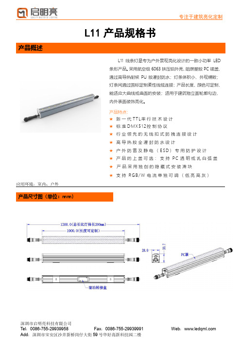
L11产品规格书产品概述应用环境:室内、户外产品尺寸图(单位:mm)L11线条灯是专为户外景观亮化设计的一款小功率LED 条形产品。
采用航空级6063挤压铝外壳,阻燃塑胶PC端盖,通过高导热耐候PU胶灌封防水;灯条体积小,外观精致;灯条间通过国标定制柔性线缆连接;产品长度、顔色可定制,能适应大曲线或曲面的安装;适用于建筑物立面轮廓勾边,内外表面装饰亮化。
产品特点:★新一代T T L串行技术设计★标准D M X512控制协议★行业领先的无线扣式防拽连接设计★高导热胶全灌封防水设计★户外防雷及静电(E S D)专用防护设计★产品的上盖可选:支持P C透明或乳白弧盖★产品采用独创的隐藏式安装滑块★支持R G B/W电流单独可调(低亮高灰)技术参数产品选型表基 本 参 数 色 彩/灰 度 RGB/W 各256级灰度; 光 源 类 型 3535 /5050 /2835 光 源 数 量48-72pcs/米 (0.25米-1米,长度可以按要求定制)材 质 铝喷涂外壳 / 阳极氧化 + 光学PC 罩寿 命 50,000h 重 量 710g/米 光 电 参 数 工 作 电 压 DC24V最 大 功 率 12-20W/米 RGB 光 强 180cd/米白 光 360cd/米 光 束 角 30° / 45° / 60° / 90° / 120°电 气 等 级 III 类其 它 参 数 工 作 温 度 -20°C to 50°C 储 存 温 度 -40°C to 70°C 防 护 等 级IP66配光曲线规格型号 光源 数量 光源类型 颜色控制类型 DC 工作电压 功率 白色 光强 DA028-48AT 48PCS 3535 RGB/W 单线串行TTL 24V 12W 120cd DA028-48AD 48PCS 3535 RGB/W DMX512 24V 12W 120cd DA028-48XD 48PCS 5050 RGBW DMX512 24V 15W 180cd DA028-48CN 48PCS 3535 2835 W 无控制 24V 12W 240cd DA028-60AT 60PCS 3535 RGB/W 单线串行TTL 24Vz 15W 150cd DA028-60AD 60PCS 3535 RGB/W DMX512 24V 15W 150cd DA028-60XD 60PCS 5050 RGBW DMX512 24V 20W 225cd DA028-60CN 60PCS 3535 2835 W 无控制 24V 15W 300cd DA028-72AT 72PCS 3535 RGB/W 单线串行TTL 24V 18W 180cd DA028-72AD 72PCS 3535 RGB/W DMX512 24V 18W 180cd DA028-72CN72PCS3535 2835W无控制24V18W360cd安装件外观尺寸安装底座尺寸图(单位mm);固定式安装底座安装方式示意:①安装载体钻孔,装膨胀胶塞:在载体上按灯具安装位置做好记号,并钻孔(建议用6mm钻头);把膨胀胶塞用锤子敲入钻孔里(注:胶塞不可松动);②固定灯具安装底座:将灯具安装底座孔位对准膨胀胶塞孔,选用合适的自攻螺丝将灯具安装底座固定到安装载体上;③灯具安装:将灯具对准灯具安装底座,并扣到灯具安装底座上;④灯具加固,完成安装:装好灯具后,从侧下边打两个自攻螺丝将型材上盖与型材安装底座固定在一起,防止型材上盖坠落。
贴片LED1206规格书

SEC.A-A
A
1.75 [0.07"]
0.20 [0.01"]
5.25 [0.21"]
8.00 [0.31"]
1.05 [0.04"] 4.00 [0.16"]
A
�
Arrangement of Tape
500 hrs
0/22
Low Temperature Life Test
1000 hrs
0/22
TAIWAN TONGJIA OPTOELECTRONICS TECHNOLOGY CO., LTD DONGGUAN TONGJIA OPTOELECTRONICS TECHNOLOGY CO., LTD
Test circuit and handling precautions
� Test circuit
+ -
R V
LED
� Handling precautions 1. Over-current-proof Customer must apply resistors for protection; otherwise slight voltage shift will cause big current change (Burn out will happen). 2. Storage 2.1 It is recommended to store the products in the following conditions: Humidity: 60% R.H. Max. Temperature : 5℃~30℃(41℉~86℉) 2.2 Shelf life in sealed bag: 12 month at <5℃~30℃ and <30% R.H. after the package is Opened, the products should be used within a week or they should be keeping to stored at≦20 R.H. with zip-lock sealed. 3. Baking It is recommended to baking before soldering when the pack is unsealed after 72hrs. The Conditions are as followings: 3.1 60±3℃ x(12~24hrs) and <5%RH, taped reel type 3.2 100±3℃ x(45min~1hr), bulk type 3.3 130±3℃ x(15~30min), bulk type
亿光槽型对射式光电开关 ITR9707
亿光槽型对射式光电开关ITR9707鼠标专用光遮断器
文章出处:广州市超毅电子有限公司
光电开关(ITR)英文为PhotoInterrupter中文为光遮断器,光断续器,光电开关。
亿光光电开关也属于红外线不可见光产品,是一种小型光电元器件,它可以检测出其接收到的光强的变化。
光电开关是光学电子装置的一种,它是通过电信号与光信号互为转换,其组合了发光与受光元件,用以检查物体为目的之一种装置。
亿光代理商超毅电子在此推荐一款亿光光电开关ITR9707,是超毅电子主推产品。
在代理亿光产品中也是销售也是名列前茅的,那它有什么优势才让市场那么受欢迎呢?下面我们一起去了解下。
.
亿光光电开关ITR9707结构:是款槽型对射式光电开关,由一个红外发光二极管和一个NPN型硅光电晶体管组成的光电开关,光电晶体管接收红外辐射了。
这是正常的情况。
但当对象之间有物体时,光电晶体管无法接收辐射红外线了。
亿光光电开关ITR9707参数图:
亿光光电开关ITR9707的优势:光的发射与接收距离宽(5.2mm),能快速的响应时间,截止可见波长λP=940海里,传感度精确,PWB封装,无铅,产品符合RoHS标准。
主要应用在鼠标,复印机,开关扫描仪,软盘驱动程序,无触点开关和pc看板等上面。
亿光光电开关ITR9707尺寸图:
亿光代理商超毅电子是亿光的15年合作伙伴,拥有着丰富的亿光光电开关的市场经验,因此,如果对于槽型对射式光电开关和反射式光电开关的相关应用资料跟规格参数,可直接联系超毅,超毅电子会为您提供最专业的技术支持。
免费咨询热线:4008-800-932。
12路智能调光器

确认无误后,把产品放回包装,置于符合存储条件的位置,等待最后的安装。
安全知识
LT-1210KA 是专业的日光灯智能调光器,符合欧洲安全标准:EN60439,EN60950, 它属于Ⅰ类设备,按 EN 60439 设计生产,按当地规格强制安全接地。 为防止任何触电事故,请不要打开外壳和防护措施,正常操作无需了解设备内部情况。 如设备有损坏必须由专业人员检查和维修,在检查和维修之前请确认电源已切断。
控制器的安装环境要求 控制器的安装尺寸要求 控制器的固定和安装 电源线的连接 主供电网络形式 供电电缆接线要求 接线端口 星形系统 单相变换 日光灯调光器的安装方法 输出连接 控制信号的连接方式及走线要求 协议简介:DMX512/1990 协议简介:LT-NET 控制电缆连接标准 工作状态及方式的选择 各类检测、保护及恢复方法
调光器可以安装在照明现场、配电室及通风良好的 配电柜内。调光器应正面垂直地安装在墙壁上。
调光器背面有四个安装孔,可用 Ф6 螺丝将调光器 固定在机架上或用 Ф6 膨胀螺栓固定在墙上。具体安装 尺寸见安装尺寸图。
警告!!! 连接不适当的电源可能会使 LT-1210KA 造成一些不可恢复的损坏,,使用前有必要 检查连接设备的电源,在通电前保证供电端 N 线连接在调光器的 N 线汇流排!
控制信号的连接方式及走线要求
LT-1210KA 为双信号接口,可以由灯光控制台通过 DMX512 信号控制;也可以接入 LT-NET 控制信号或由兼容 LT-NET 信号的中控系统控制。所有设备包括调光器,控制面板和 控制部件都通过一条控制电缆按手牵手方式连接,构成一个控制系统。如果系统过大,可划分 为多个子系统,然后将各子系统通过网桥与主干控制连接起来构成主系统。
超毅亿光2835灯珠命名规则书(1W)

SMD High Power LED67-22ST/KK2C-HXXXXXXXX5670Z15/2TFeatures‧PLCC-2 packageTop view‧white LED˙High luminous intensity output˙Wide viewing angle˙Pb-free˙RoHS compliant˙ANSI BinningDescriptionThe Everlight 67-22S package has high efficacy, high CRI, low power consumption, wide viewing angle and a compact form factor. These features make this package an ideal LED for all lighting applications.ApplicationsGeneral lighting‧Decorative and Entertainment Lighting‧Indicators‧Illumination‧Switch lights‧Product Number Explanation67–22ST / K K 2 C – H XX XX XX XX XXXX Z15 / 2TBin Group of Forward VoltageBin Group of Max. Luminous FluxBin Group of Min. Luminous FluxMax. Color temperatureMin. Color temperatureBin Code of Color Rendering Index Table of Color Rendering IndexSymbol DescriptionM CRI(Min.) : 60N CRI(Min.) : 65L CRI(Min.) : 70Q CRI(Min.) : 75K CRI(Min.) : 80P CRI(Min.) : 85H CRI(Min.) : 90Note:Tolerance of Color Rendering Index: ±2Table of Forward Current IndexSymbol DescriptionZ15 I F:150mAExample:67-22ST/KK2C-H3030S1S55670Z15/2TCRI 80(Min.)CCT 3000KFlux 100-150lmV F 5.6-7.0VI F150mAMass Production ListProductCRIMin.(1)CCT(K)Φ(lm)Min. (2)Φ(lm)Max. (2)67-22ST/KK2C-H2727S1S55670Z15/2T 80 2700K 100 150 67-22ST/KK2C-H3030S1S55670Z15/2T 80 3000K 100 150 67-22ST/KK2C-H4040S1BS65670Z15/2T 80 4000K 105 160 67-22ST/KK2C-H5050S2S65670Z15/2T 80 5000K 110 160 67-22ST/KK2C-H5757S2S65670Z15/2T 80 5700K 110 160 67-22ST/KK2C-H6565S1BS65670Z15/2T 80 6500K 105 160 Notes:1. Tolerance of Color Rendering Index: ±22. Tolerance of Luminous flux: ±11%.Device Selection GuideChipMaterialsEmitted Color Resin ColorInGaNCool WhiteNeutral WhiteWarm WhiteWater ClearAbsolute Maximum Ratings (T Soldering=25℃)Parameter Symbol Rating Unit Forward Current I F180 mA Peak Forward Current (Duty 1/10 @10ms) I FP300 mA Power Dissipation P d1260 mW Operating Temperature T opr-40 ~ +85 ℃Storage Temperature T stg-40 ~ +100 ℃Thermal Resistance (Junction / Soldering point) R th J-S17 ℃/W Junction Temperature T j115 ℃Soldering Temperature Tsol Reflow Soldering : 260 ℃ for 10 sec. Hand Soldering : 350 ℃ for 3 sec.Note:The products are sensitive to static electricity and must be carefully taken when handling productsElectro-Optical Characteristics (T Soldering=25℃)Parameter Symbol Min. Typ. Max. Unit ConditionLuminous Flux(1)Φ100 ----- 160 lm I F=150mA Forward Voltage(2)V F 5.6 ----- 7.0 V I F=150mA Color Rendering Index(3)Ra 80 ----- ----- I F=150mA Viewing Angle 2θ1/2----- 120 ----- deg I F=150mA Reverse Current I R----- ----- 50 µΑ V R =10VNotes:1. Tolerance of Luminous flux: ±11%.2. Tolerance of Forward Voltage: ±0.1V.3. Tolerance of Color Rendering Index: ±2Bin Range of Luminous FluxBin Code Min. Max. Unit ConditionS1 100 110 lm I F =150mAS1B 105 110 S2 110 120 S3 120 130 S4 130 140 S5 140 150 S6150160Note:Tolerance of Luminous flux: ±11%.Bin Range of Forward VoltageGroupBin Code Min. Max. Unit Condition56705#6 5.6 5.7 V I F =150mA5#7 5.7 5.8 5#8 5.8 5.9 5#9 5.9 6.0 6#0 6.0 6.1 6#16.1 6.2 6#2 6.2 6.3 6#3 6.3 6.4 6#4 6.4 6.5 6#5 6.5 6.6 6#6 6.6 6.7 6#7 6.7 6.8 6#8 6.8 6.9 6#96.97.0Note:Tolerance of Forward Voltage: ±0.1V.The C.I.E. 1931 Chromaticity DiagramBin Range of Chromaticity CoordinatesCCT Bin Code CIE_x CIE_y Bin Code CIE_x CIE_y2700K 27K-A0.4813 0.431927K-D0.4700 0.41260.4687 0.4289 0.4627 0.41090.4621 0.4169 0.4588 0.40410.4667 0.4180 0.4544 0.40300.4627 0.4109 0.4483 0.39190.4700 0.4126 0.4593 0.3944Reference Range:2580K~2700K27K-B0.4687 0.428927K-C0.4465 0.40710.4562 0.4260 0.4373 0.38930.4465 0.4071 0.4483 0.39190.4539 0.4088 0.4544 0.40300.4576 0.4158 0.4502 0.40200.4621 0.4169 0.4539 0.4088Reference Range:2700K~2870K27K-F0.4667 0.418027K-G0.4627 0.41090.4576 0.4158 0.4539 0.40880.4539 0.4088 0.4502 0.40200.4627 0.4109 0.4588 0.4041Reference Range: 2665K~2770KCCT Bin Code CIE_x CIE_y Bin Code CIE_x CIE_y3000K 30K-A0.4562 0.426030K-D0.4465 0.40710.4430 0.4212 0.4388 0.40430.4375 0.4096 0.4355 0.39770.4422 0.4113 0.4311 0.39620.4388 0.4043 0.4259 0.38530.4465 0.4071 0.4373 0.3893Reference Range:2870K~3000K30K-B0.4430 0.421230K-C0.4221 0.39840.4299 0.4165 0.4147 0.38140.4221 0.3984 0.4259 0.38530.4297 0.4011 0.4311 0.39620.4328 0.4079 0.4267 0.39460.4375 0.4096 0.4297 0.4011Reference Range:3000K~3220K30K-F0.4422 0.411330K-G0.4388 0.40430.4328 0.4079 0.4297 0.40110.4297 0.4011 0.4267 0.39460.4388 0.4043 0.4355 0.3977Reference Range:2960K~3080KThe C.I.E. 1931 Chromaticity DiagramBin Range of Chromaticity CoordinatesCCT Bin Code CIE_x CIE_y Bin Code CIE_x CIE_y4000K 40K-A0.4006 0.404440K-D0.3952 0.38800.3871 0.3959 0.3873 0.38310.3843 0.3858 0.3854 0.37680.3890 0.3887 0.3810 0.37410.3873 0.3831 0.3784 0.36470.3952 0.3880 0.3898 0.3716Reference Range:3700K~3970K40K-B0.3871 0.395940K-C0.3703 0.37260.3736 0.3874 0.3670 0.35780.3703 0.3726 0.3784 0.36470.3779 0.3773 0.3810 0.37410.3793 0.3828 0.3764 0.37130.3843 0.3858 0.3779 0.3773Reference Range:3970K~4270K40K-F0.3890 0.388740K-G0.3873 0.38310.3793 0.3828 0.3779 0.37730.3779 0.3773 0.3764 0.37130.3873 0.3831 0.3854 0.3768Reference Range:3870K~4080KThe C.I.E. 1931 Chromaticity DiagramBin Range of Chromaticity CoordinatesCCT Bin Code CIE_x CIE_y Bin Code CIE_x CIE_y5000K 50K-A0.3551 0.376050K-D0.3533 0.36240.3464 0.3688 0.3482 0.35830.3456 0.3604 0.3477 0.35300.3487 0.3629 0.3448 0.35070.3482 0.3583 0.3441 0.34280.3533 0.3624 0.3515 0.3487Reference Range:4745K~5000K50K-B0.3464 0.368850K-C0.3371 0.34930.3376 0.3616 0.3366 0.33690.3371 0.3493 0.3441 0.34280.3422 0.3533 0.3448 0.35070.3425 0.3579 0.3418 0.34830.3456 0.3604 0.3422 0.3533Reference Range:5000K~5310K50K-F0.3487 0.362950K-G0.3482 0.35830.3425 0.3579 0.3422 0.35330.3422 0.3533 0.3418 0.34830.3482 0.3583 0.3477 0.3530Reference Range:4910K~5120KCCT Bin Code CIE_x CIE_y Bin Code CIE_x CIE_y5700K 57K-A0.3376 0.361657K-D0.3371 0.34930.3292 0.3539 0.3321 0.34470.3292 0.3464 0.3320 0.34010.3321 0.3490 0.3293 0.33770.3321 0.3447 0.3294 0.33060.3371 0.3493 0.3366 0.3369Reference Range:5310K~5700K57K-B0.3292 0.353957K-C0.3215 0.33530.3207 0.3462 0.3222 0.32430.3215 0.3353 0.3294 0.33060.3262 0.3395 0.3293 0.33770.3261 0.3436 0.3263 0.3350.3292 0.3464 0.3262 0.3395Reference Range:5700K~6020K57K-F0.3321 0.349057K-G0.3321 0.34470.3261 0.3436 0.3262 0.33950.3262 0.3395 0.3263 0.33500.3321 0.3447 0.3320 0.3401Reference Range:5520K~5780KCCT Bin Code CIE_x CIE_y Bin Code CIE_x CIE_y6500K 65K-A0.3205 0.348165K-D0.3213 0.33710.3117 0.3393 0.3161 0.33200.3125 0.3328 0.3166 0.32810.3157 0.3360 0.3136 0.32510.3161 0.3320 0.3145 0.31870.3213 0.3371 0.3221 0.3261Reference Range:6020K~6500K65K-B0.3117 0.339365K-C0.3048 0.32090.3028 0.3304 0.3068 0.31130.3048 0.3209 0.3145 0.31870.3100 0.3259 0.3136 0.32510.3093 0.3297 0.3106 0.32220.3125 0.3328 0.31 0.3259Reference Range:6500K~7050K65K-F0.3157 0.336065K-G0.3161 0.33200.3093 0.3297 0.3100 0.32590.3100 0.3259 0.3106 0.32220.3161 0.3320 0.3166 0.3281Reference Range:6300K~6690KNotes:1. The value is based on driving current by 150mA.2. Tolerance of Chromaticity Coordinates: ±0.01.Spectrum DistributionTypical Electro-Optical Characteristics CurvesTj - Junction Temperature (oC)01530456075901051201351501651800.00.20.40.60.81.01.2R e l a t i v e L u m i n o u s I n t e n s i t yForward Current(mA)Typical Electro-Optical Characteristics Curves25405570851001150.00.20.40.60.81.01.2Tj - Junction Temperature ( oC )R e l a t i v e L u m i n o u s F l u x5.45.6 5.86.0 6.2 6.4 6.6 6.8153045607590105120135150165180I F -F o r w a r d C u r r e n t (m A )V F - Forward V oltage (V )20406080100306090120150180210F o r w a r d C u r r e n t (m A )Soldering Temperature (oC )0.70.80.91.080°90°50°60°70°40°20°0°10°30°Package DimensionNote:Tolerance unless mentioned is ±0.15 mm; Unit = mmMoisture Resistant Packing MaterialsLabel Explanation‧CPN: Customer’s Product Number ‧P/N: Product Number ‧QTY: Packing Quantity‧CAT: Luminous Intensity Rank ‧HUE: Dom. Wavelength Rank ‧REF: Forward Voltage Rank ‧LOT No: Lot NumberReel DimensionsNote:Tolerances unless mentioned ±0.1mm. Unit = mmCarrier Tape Dimensions: Loaded Quantity 250/500/1000/2000 pcs Per ReelNote:1.Tolerance unless mentioned is ±0.1mm; Unit = mmMoisture Resistant Packing ProcessLabel LabelReliability Test Items and ConditionsThe reliability of products shall be satisfied with items listed below.Confidence level:90%LTPD:10%No. Items Test Condition Test Hours/Cycles Sample Size Ac/Re1 Reflow Soldering Temp. : 260℃/10sec. 6 Min. 22 PCS. 0/12 Thermal Shock H : +100℃20min∫10 secL : -10℃20min200 Cycles22 PCS. 0/13 Temperature Cycle H : +100℃30min∫5 minL : -40℃30min200 Cycles 22 PCS. 0/14 High Temperature/HumidityReverse Bias Ta=85℃,85%RH1000 Hrs. 22 PCS. 0/15 High Temperature/HumidityOperationTa=85℃,85%RH,I F = 100 mA1000 Hrs. 22 PCS. 0/16 Low Temperature Storage Ta=-40℃1000 Hrs. 22 PCS. 0/17 High Temperature Storage Ta=85℃1000 Hrs. 22 PCS. 0/18 Low TemperatureOperation LifeTa=-40℃,I F = 180 mA1000 Hrs. 22 PCS. 0/19 High TemperatureOperation/ Life#1Ta=25℃,I F = 180 mA1000 Hrs. 22 PCS. 0/110 High TemperatureOperation/ Life#2Ta=55℃,I F =180 mA1000 Hrs. 22 PCS. 0/111 High TemperatureOperation/ Life#3Ta=85℃,I F = 100 mA1000 Hrs. 22 PCS. 0/1Precautions for Use1. Over-current-proofCustomer must apply resistors for protection; otherwise slight voltage shift will cause big current change (Burn out will happen).2. Storage2.1 Do not open moisture proof bag before the products are ready to use.2.2 Before opening the package: The LEDs should be kept at 30℃or less and 90%RH or less.2.3 After opening the package: The LED's floor life is 168 Hrs under 30℃ or less and 60% RH or less. If unusedLEDs remain, it should be stored in moisture proof packages.2.4 If the moisture absorbent material (silica gel) has faded away or the LEDs have exceeded the storage time,baking treatment should be performed using the following conditions.Baking treatment: 60±5℃for 24 hours.3. Soldering Condition3.1 Pb-free solder temperature profile260 Max.Above255 C C3.2 Reflow soldering should not be done more than two times.3.3 When soldering, do not put stress on the LEDs during heating.3.4 After soldering, do not warp the circuit board.4. Soldering IronEach terminal is to go to the tip of soldering iron temperature less than 350℃for 3 seconds within once in less than the soldering iron capacity 25W. Leave two seconds and more intervals, and do soldering of each terminal. Be careful because the damage of the product is often started at the time of the hand solder.5. RepairingRepair should not be done after the LEDs have been soldered. When repairing is unavoidable, a double-head soldering iron should be used (as below figure). It should be confirmed beforehand whether the characteristics of the LEDs will or will not be damaged by repairing.。
300-1100nmled

300-1100nmled
300-1100nm LED是一种发光二极管,其发光波长范围在300纳米到1100纳米之间。
这种LED的广泛应用领域包括照明、通信、显示和生物医学等。
在照明方面,300-1100nm LED可以用于室内和室外照明。
由于其发光波长范围广泛,可以提供不同颜色和亮度的光线。
此外,LED的低能耗和长寿命特性使其成为节能照明的理想选择。
在通信方面,300-1100nm LED可以用于光通信系统中的光源。
光通信是一种高速、高带宽的数据传输方式,而LED作为光源可以提供稳定的光信号。
此外,LED还可以用于红外通信系统中,其发光波长在900纳米到1100纳米之间,可以穿透一定的障碍物进行通信。
在显示方面,300-1100nm LED可以用于各种显示器件,如液晶显示器(LCD)和有机发光二极管(OLED)。
LED作为背光源可以提供均匀的光线,使得显示器的亮度和对比度更好。
而在OLED中,LED作为发光元件可以提供高亮度和高色彩饱和度的显示效果。
在生物医学方面,300-1100nm LED可以用于医疗设备和治疗仪器。
例如,在光治疗中,LED可以发射特定波长的光线,用于治疗皮肤疾病、伤口愈合和疼痛缓解等。
此外,LED还可以用于光谱分析仪器中,用于检测和分析生物样品中的化学成分。
300-1100nm LED在照明、通信、显示和生物医学等领域都有广泛的
应用。
其特点包括发光波长范围广泛、低能耗、长寿命、高亮度和高色彩饱和度等。
随着技术的不断发展,LED的应用领域还将继续扩大,为各个行业带来更多的创新和便利。
高效率四色LED指示灯产品说明书

Iv (mcd) [2] @ 10mA
Min. Typ.
12
30
*10
*20
8
15
*8
*15
10
25
*10
*25
Viewing Angle [1]
2θ1/2
40°
40°
40°
Electrical / Optical Characteristics at TA=25°C
Symbol
Parameter
Device
Power dissipation
75
DC Forward Current
30
Peak Forward Current [1]
160
Reverse Voltage
Operating/Storage Temperature
Lead Solder Temperature [2]
Lead Solder Temperature [3]
Notes: 1. 1/10 Duty Cycle, 0.1ms Pulse Width. 2. 2mm below package base. 3. 5mm below package base.
SPEC NO: DSAG9328 APPROVED: WYNEC
REV NO: V.2A CHECKED: Allen Liu
SPEC NO: DSAG9328 APPROVED: WYNEC
REV NO: V.2A CHECKED: Allen Liu
DATE: SEP/16/2013 DRAWN: D.N.Huang
PAGE: 6 OF 7 ERP: 1102014033
SPEC NO: DSAG9328 APPROVED: WYNEC
- 1、下载文档前请自行甄别文档内容的完整性,平台不提供额外的编辑、内容补充、找答案等附加服务。
- 2、"仅部分预览"的文档,不可在线预览部分如存在完整性等问题,可反馈申请退款(可完整预览的文档不适用该条件!)。
- 3、如文档侵犯您的权益,请联系客服反馈,我们会尽快为您处理(人工客服工作时间:9:00-18:30)。
Technical Data Sheet
Photolink- Fiber Optic Transmitter
PLT131/T2/12 Features
• High speed signal transmission(12Mbps NRZ Signal)
• TTL interface compatible
• +3~+5V single power source
Descriptions
Photolink is assembled with plastic housing and
opto-electric component packaged with a 660nm
AlGaAs LED and drive IC. It transforms the
electrical signal to optical signal and be transmitted
by 1mm diameter plastic optical fiber.
The component is operated at +3~+5V and has
high performance at low dissipation current, steady
light output and efficient light coupling.
Applications
• Digital audio equipment
• CD player
• DVD player
Device Selection Guide
Chip Dissipation
Current(mA) Fiber Coupling Light Output
(dBm)
Material λp(nm) Operating
Voltage
(Vcc) Typ. Max. Min. Typ. Max.
AlGaAs 660 +3.0~5.0 5.5 10 -21 -- -15
Device NO.:DPL-131-017
Package Dimensions
Notes: 1.All dimensions are in millimeters. Pin Function: 1.GND
2.General Tolerance :±0.1mm
2.Vcc
3.Vin
Using Method
PCB Layout for Electrical Circuit
Notes: 1. unit:mm
2.Dimension Tolerance:±0.1mm
3.Substrate Thickness:1.6mm
Device NO.:DPL-131-017
Vin Vcc GND
PLT131/T2/12
Absolute Maximum Ratings( Ta = 25℃)
Parameter Symbol Rating Unit Supply Voltage Vcc -0.5 to 7 V
DC Input Voltage Vin -0.5 to Vcc+0.5 V
Storage Temperature Tstg -40 to 70 ℃
Operating Temperature Topr -20 to 70 ℃
Soldering Temperature Tsol 260* ℃
* Soldering time ≤ 10 s.
Electro-Optical Characteristics
Parameter Symbol Conditions MIN. TYP. MAX. Unit Operating Voltage Vcc Low Voltage 2.75 3.00 3.25 V
High Voltage 4.75 5.00 5.25 V Peak Emission Wavelength λp 640 660 680 nm Transmission Rate NRZ Code DC - 12 Mbps Transmission Distance Using APF* 0.2 - 20 m Fiber Coupling Output Power Pf *1 -21 -18 -15 dBm Dissipation Current Icc *2 3 - 10 mA High Level Input Voltage V IH 2 - - V Low Level Input Voltage V IL- - 0.8 V Low to High Delay Time t pLH*3 - - 180 ns High to Low Delay Time t pHL*3 - - 180 ns Pulse Width Distortion ∆tw *3 -30 - 30 ns
*All Plastic Optical Fiber(970/1000um)
Device NO.:DPL-131-017
PLT131/T2/12
Measuring Method
*1
Measuring method of optical output coupling fiber
*2 Input voltage/power dissipation measuring method
*3 Pulse response measuring method
Device NO.:DPL-131-017。