sick光电开关型
SICK光电开关DR35说明说

SICK光电开关DR35说明说SICK光电开关大部分迷你型普通LED光源的漫反射式光电开关检测距离在1米以内,镜反射光电开关检测距离10米以内,对射型光电开关在20米左右,而激光光源光电开关的检测距离会高于这个范围。
对应于小型和紧凑型的光电开关,检测距离会进一步延伸,西克目前可提供远的对射型光电开关距离可达350米。
SICK光电开关用于工业,也参与日常生活。
下面主要介绍了区分各种光电传感器的不同方法,分别与检测方法和光源类型进行分析判断。
SICK光电开关在一般情况下,有三部分构成,它们分为:发送器、接收器和检测电路。
发送器对准目标发射光束,发射的光束一般来源于半导体光源,发光二极管(LED)、激光二极管及红外发射二极管。
光束不间断地发射,或者改变脉冲宽度。
接收器有光电二极管、光电三极管、光电池组成。
在接收器的前面,装有光学元件如透镜和光圈等。
在其后面是检测电路,它能滤出有效信号和应用该信号。
首先,检测方法不同①在光量方法中,大多数光电开关用于以光量的方式检测物体的存在或不存在,也就是说,光源被物体遮挡,或者光量由于反射、辐射和阴影而改变,以检测物体的存在或不存在。
②三角测距法,因为光电开关容易受到物体表面光滑度、粗糙度和颜色的影响,所以在一些要求较高的地方需要使用距离法。
③激光测量法,激光光电开关向待测目标发射光信号,然后接收目标自身反射的光信号,*后通过测量光信号来回通过的时间来计算目标的距离。
其次,光源种类不同,因为大多数光源是发光二极管(LED),所以应该根据不同的用途来区分它们。
1、发光二极管(LED)型(可见光、近红外光):这种光电开关具有易于调制、使用寿命长、体积小、功耗低、耐冲击等优点。
它是一个理想的光源,可以用于各种目的。
2、荧光(可见光):主要用于光电系统的光电开关(图像传感器等)。
)具有所需的长度。
3、气体激光类型(可见光):光束相对较强,用于探伤系统、条形码系统以及强光衰减较大的场合,如蒸汽、烟雾、火焰等。
SICK施克IME18电感式接近开关选型手册(中文版)
安装形式 连接形式
防护等级 开关频率 尺寸 短路保护 极性倒接保护 上电脉冲抑制 冲击振动应力 工作环境温度 外壳材料 紧固扭矩 认证 绝缘等级 UL认证 1)在I a 最大时 2)无荷载
12mm DC-3线 DC10-30V
DC ≤ 10% ≤ 2V1) ≤ 10mA2) ≤ 200mA ≤ 100ms 5-15% ≤ 2%(Ub,Ta保持不变)3) ± 10% 符合标准EN60947-5-2
检测距离 5mm
电感式接近开关
短路保护(脉冲) 铜芯镀镍外壳,螺纹尺寸 M18 x1mm 防护等级IP67 齐平安装
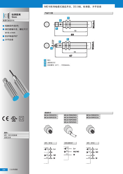
IME18系列电感式接近开关,DC-3线,标准型,齐平安装
产品尺寸图
接头 LED指示灯 安装螺母(2个),外径24mm。
附件: 4针,M12 连接器 安装支架
234 工业传感器
连接形式
工 业 传 感 器
30g,11ms/10-55Hz,1mm -25℃... +75℃ 铜镀镍,塑料(PA6) 40 Nm
cULus Listed
3)Sr 4)符合标准EN60529
5)螺纹直径x螺距(mm) 6)短路保护(脉冲)
修正因素
下列为参考数值,实际中因型号的不同而不同
钢铁(ST37) 不锈钢(V2A) 铝(实心) 铜(Cu)
6)
IME18
IME18-
05BNO 05BNO 05BNS 05BNS 05BPO 05BPO 05BPS 05BPS ZC0S ZW2S ZC0S ZW2S ZC0S ZW2S ZC0S ZW2S
工 业 传 感 器
,11ms/10-55Hz,1mm -25℃... +75℃ 铜镀镍,塑料(PA6) 40 Nm
德国SICK传感器 PPT课件

电子式 T型槽磁性气缸开关Biblioteka 电子式 T型槽磁性气缸开关
• 使用SICK-ASIC芯片技术 (GMR),具有很高的精度;
• 开关点具有最小的偏差(+/-5%) • 滞后最小(0.7mT+/-0.1mT) • 非常坚固; • 操作简单; • 配置固紧螺丝; • "Drop-in"直接安装方式; • IP67/68/69K防护等级;
近开关
• 具备创新理念的IME接近开关确保您的设备高效, 稳定,具有创新性专用集成算法的ASIC技术以及 内灌以"HOT-MELT"高抗震性材料技术的"肉体", 外套了坚固的镀镍铜"外衣",确保具有高精准检 测精度以及耐高强度震动的冲击
IMF电感式接近开关
IMF电感式接近开关
• 不锈钢外壳(1.4404/316L); • 高防护等级(IP68/IP69K); • 宽温度范围 -40 ℃… +80 ℃(短
G6迷你型电开关
• 采用SICK独创的类激光PinPoint LED光源技术, 光点明亮、精确、清晰
• 提供漫反(300mm)/镜反(7.2m)/对射(15m) 工作方式
• 提供漫反射/镜反射/镜反射透明物体/对射型/对射 灵敏度可调型等
• 大调节旋钮减少安装时间 • 亮通/暗通旋钮设计减少库存型号 • 大而明亮的LED指示灯减少安装维护成本 • 提供套装型号,安装支架和反射镜配套发货,减少
V180-2圆柱形光电开关
V180-2圆柱形光电开关
• 高亮LED红光光源 ,易于对准 • 提供漫反(1100mm)/镜反(7m)/对射
(28m)工作方式 • 提供轴向、径向两种出光方式 ,安装方便灵活 • 提供优异的背景遮蔽功能, 轴向出光1mm ~
光电开关工作原理

光电开关原理及应用一、前言光电开关是传感器大家族中的成员,它把发射端和接收端之间光的强弱变化转化为电流的变化以达到探测的目的。
由于光电开关输出回路和输入回路是电隔离的(即电缘绝),所以它可以在许多场合得到应用。
二、光电开关介绍1、工作原理光电开关(光电传感器)是光电接近开关的简称,它是利用被检测物对光束的遮挡或反射,由同步回路选通电路,从而检测物体有无的。
物体不限于金属,所有能反射光线的物体均可被检测。
光电开关将输入电流在发射器上转换为光信号射出,接收器再根据接收到的光线的强弱或有无对目标物体进行探测。
工作原理如图1所示。
多数光电开关选用的是波长接近可见光的红外线光波型。
图2是德国SICK公司的部分光电开关外型图。
2、光电开关的分类及术语解释(1)、分类①漫反射式光电开关:它是一种集发射器和接收器于一体的传感器,当有被检测物体经过时,物体将光电开关发射器发射的足够量的光线反射到接收器,于是光电开关就产生了开关信号。
当被检测物体的表面光亮或其反光率极高时,漫反射式的光电开关是首选的检测模式。
②镜反射式光电开关:它亦集发射器与接收器于一体,光电开关发射器发出的光线经过反射镜反射回接收器,当被检测物体经过且完全阻断光线时,光电开关就产生了检测开关信号。
③对射式光电开关:它包含了在结构上相互分离且光轴相对放置的发射器和接收器,发射器发出的光线直接进入接收器,当被检测物体经过发射器和接收器之间且阻断光线时,光电开关就产生了开关信号。
当检测物体为不透明时,对射式光电开关是最可靠的检测装置。
④槽式光电开关:它通常采用标准的U 字型结构,其发射器和接收器分别位于U型槽的两边,并形成一光轴,当被检测物体经过U型槽且阻断光轴时,光电开关就产生了开关量信号。
槽式光电开关比较适合检测高速运动的物体,并且它能分辨透明与半透明物体,使用安全可靠。
⑤光纤式光电开关:它采用塑料或玻璃光纤传感器来引导光线,可以对距离远的被检测物体进行检测。
SICK 光电开关-W45 选型
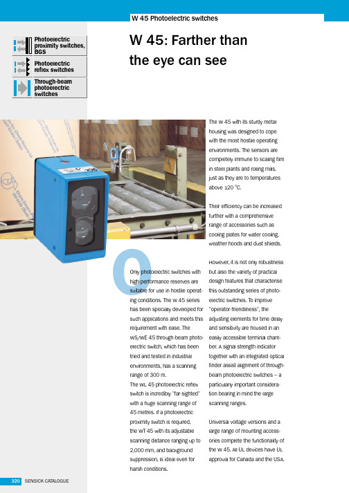
O321SENSICK CATALOGUEWL 27-2n A WS/WE 45through-beam photoelectric switch monitors tear-off on a paper web.m The robust designand large scanning distance are of advantage to the WT 45 photoelectric proximity switch when used to check for tear-off on a paper rolling machine.n Scale, steam andheat in a rolling mill does not affect the WT 45 – here used to detect the pre-sence of steel slabs.v Extreme operating conditions exist insteel making plants – the WT 45 photo-electric proximity switch is ideal for many applications, such as detecting metal sheets before they are wound onto coils.W 45322SENSICK CATALOGUEWT 45 Photoelectric proximity switches, background suppression, infrared light -- DCL+M TENC Q Q0.5 – 12 s 0.015 – 0.3 st 0without time delayt 0without time delay t 3ON-delay when object t 1ON-delay when object enters detection zone enters detection zone t 4OFF-delay when object t 2OFF-delay when object leaves detection zone leaves detection zoneLED signal strength indicatorStandard direction of the material being scanned Centre of optical axis, receiver Centre of optical axis, senderThreaded mounting hole M 6 – 8 mm deep Alignment sightScanning distance adjustment Time adjustmentTime delay selector switch Terminal strip Status indicator11s Robust metal housing s Infrared lightsAdjustable background suppressionsFront lens heating, optionalC ਠ10987654321323SENSICK CATALOGUE WL 27-2WT 45(mm)200016001200800255101520% o f s c a n n i n g d i s t a n c e P 250P 260N 250N 260Scanning distance on black, 6% remission 1Scanning distance on grey, 18% remission11)Average service life 100,000 h at T A = +25 °C 2) Limit values3)May not exceed or fall short of V S tolerances4)Without load5) Signal transit time with resistive load 6)With light/dark ratio 1:18)Up to 140°C with cooling plates (see Accessories)7)A =V S connections reverse-polarityprotectedB =Output Q N and Q P short-circuitprotectedC =Interference pulse suppression200800120016002000324SENSICK CATALOGUEWT 45 Photoelectric proximity switches, background suppression, infrared light -- DCPEL1N0.5 – 12 st 0without time delayt 1ON-delay when object enters detection zone t 2OFF-delay when object leaves detection zoneLED signal strength indicatorStandard direction of the material being scanned Centre of optical axis, receiver Centre of optical axis, senderM 6 threaded mounting hole – 8 mm deep Alignment sightScanning distance adjustment Time adjustmentTime delay selector switchleft: light-switching, right: dark-switching Terminal strip Status indicator11s Robust metal housing s Infrared lightsAdjustable background suppressionsFront lens heating, optional10987654321Cਠ325SENSICK CATALOGUE WL 27-2WT 45(mm)200016001200800255101520% o f s c a n n i n g d i s t a n c e R250R 2601)Average service life 100,000 h at T A = +25°C2)Provide suitable spark suppression for inductive or capacitive loads 3)With light/dark ratio 1:14)A =V S connections reverse-polarityprotectedC =Interference pulse suppression 5)Up to 140°C with cooling plates (see Accessories)200800120016002000Scanning distance on black, 6% remission 1Scanning distance on grey, 18% remission2326SENSICK CATALOGUEWL 45 Photoelectric reflex switches, red light -- DCL+M TEAlarm Q Q Centre of optical axis, sender Centre of optical axis, receiver LED signal strength indicatorM 6 threaded mounting hole – 8 mm deep Alignment sightSensitivity adjustment Time adjustmentTime delay selector switch Terminal strip Status indicators Robust metal housing s Red lights Adjustable sensitivitys Front lens heating, optional sPre-failure signalling output109876543210.5 – 12 s 0.015 – 0.3 st 0without time delayt 0without time delay t 3ON-delay when object t 1ON-delay when object enters detection zone enters detection zone t 4OFF-delay when object t 2OFF-delay when object leaves detection zone leaves detection zoneC ਠ327SENSICK CATALOGUEWL 27-2WL 451001011(m)10100OperatingreserveP250P260N250N2600(m)102030405060s Operating range s Scanning range,max. typical1)Average service life 100,000 hat T A= +25°C2) Limit values3)May not exceed or fall short ofV S tolerances4)Without load5) Signal transit time with resistive load6)With light/dark ratio 1:17) Reference voltage 50 V DC9)Up to 140°C with cooling plates(see Accessories)8)A=V S connections reverse-polarityprotectedB=Output Q N and Q P short-circuitprotectedC=Interference pulse suppression328SENSICK CATALOGUEPEL1NWL 45 Photoelectric reflex switches, red light -- UCCentre of optical axis, sender Centre of optical axis, receiver LED signal strength indicatorM 6 threaded mounting hole – 8 mm deep Alignment sightSensitivity adjustment Time adjustmentTime delay selector switchleft: light-switching, right: dark-switching Terminal strip Status indicators Robust metal housing s Red lights Adjustable sensitivitysFront lens heating, optional10987654321Cਠ0.5 – 12 st 0without time delayt 1ON-delay when object enters detection zone t 2OFF-delay when object leaves detection zone329SENSICK CATALOGUEWL 27-21001011(m)10100Op e r a t i n g r e s e r v e WL 45R 250R 2600(m)102030405060s Operating ranges Scanning range,max. typical1)Average service life 100,000 h at T A = +25°C2)Provide suitable spark suppressionfor inductive or capacitive loads3)With light/dark ratio 1:14)A =V S connections reverse-polarityprotectedC =Interference pulse suppression5)Up to 140°C with cooling plates (see Accessories)6L+MTEL+MAlarmQQCentre of optical axis, sender (WS)Centre of optical axis, receiver (WE)View finder lensLED signal strength indicatorM6 threaded mounting hole – 8 mm deepEyepiece for alignment aidAlignment sightSensitivity adjustmentTime adjustmentTime delay selector switchTerminal stripStatus indicators Robust metal housings Red lights Adjustable sensitivitys Front lens heating, optionals Pre-failure signalling output10119876543210.5 – 12 s0.015 – 0.3 st0without time delayt0without time delayt3ON-delay when object t1ON-delay when objectenters detection zone enters detection zonet4OFF-delay when object t2OFF-delay when objectleaves detection zone leaves detection zone C ਠ100010010110015020025030035040050(m)O p e r a t i n g r e s e r v eP 250P 260N 250N2600(m)50100150200250300350400sOperating rangesScanning range,max. typical1)Average service life 100,000 h at T A = +25 °C 2) Limit values3)May not exceed or fall short of V S tolerances4)Without load5) Signal transit time with resistive load 6)With light/dark ratio 1:18)Up to 140°C with cooling plates (see Accessories)7)A =V S connections reverse-polarityprotectedB =Output Q N and Q P short-circuitprotectedC =Interference pulse suppressionPE L1 N PE L1 NCentre of optical axis, sender (WS)Centre of optical axis, receiver (WE)View finder lensLED signal strength indicatorM6 threaded mounting hole – 8 mm deepEyepiece for alignment aidAlignment sightSensitivity adjustmentTime adjustmentTime delay selector switchleft: light-switching, right: dark-switchingTerminal stripStatus indicators Robust metal housings Red lights Adjustable sensitivitys Front lens heating, optional10119876543210.5 – 12 st0without time delayt1ON-delay when object enters detection zonet2OFF-delay when object leaves detection zone C ਠ100010010110015020025030035040050(m)O p e r a t i n g r e s e r v eR 250R2600(m)50100150200250300350400s Operating ranges Scanning range,max. typical1)Average service life 100,000 h at T A = +25°C2)Provide suitable spark suppression for inductive or capacitive loads3)With light/dark ratio 1:14)A =V S connections reverse-polarityprotectedC =Interference pulse suppression5)Up to 140°C with cooling plates (see Accessories)。
SICK全系列产品简介

NPN/PNP
IM 04: 0.4mm IM 05: 0.8mm IM 08: 1.5mm IM 12: 2mm IM 18: 5mm IM 30: 10/15mm
IP 67
-25℃ ...+70℃
IMB
圆柱形电感式 接近开关 10...30V DC 圆柱直径带螺纹: 8mm/12 mm/ 18 mm/30 mm 电感式
M20x1.5; 7/16-20
G ¼ 母头 , 根据 EN 837 多种卫生型过程连
UNF SAE #4J514 公头 ¼'' NPT; R ¼ , 根据 接等 ( LFP)
IP 67 -25℃ ...+55℃
IP 67 -40℃ ...+60℃
W27-3
光电开关 10...30V DC 12...240V DC 24...240V AC 红光 ; 红外线 ; 激光
NPN/PNP/Relay
漫反射式: 30...1100mm 30...1600mm 镜反射式:0.1...15m 对射式:0...35m
4
全系列产品简介 | SICK
6000002/2015-07-29 如有改动,恕不另行通知
产品型号 产品名称 供电电压 光源类型 输出方式
检测距离
防护等级 工作温度
W250-2
光电开关 10...30V DC 12...240V DC 24...240V AC 红光
NPN/PNP/Relay
W24-2
漫反射式:0...6m 镜反射式:4...180mm 对射式:0...5m
IP 67+ IP 69K -40℃ ...+60℃
产品型号 产品名称 供电电压 光源类型 输出方式
SICK光电传感器
SICK光电传感器WTB9-3P1161型号:WTB9-3P1161订货号:1049043产品特点传感器原理/检测原理反射式光电扫描仪, 背景抑制功能尺寸(宽 x 高 x 深) mm x 50 mm x mm外壳形状(光束出口)方形孔型M3最大开关距离20 mm ... 350 mm 1)感应距离20 mm ... 200 mm 2)光线种类可见红光光发射器PinPoint-LED 3)光点尺寸(距离)Ø mm (75 mm)轴长650 nm设置电位计,5 圈具有 90% 反射率的扫描对象(指 DIN 5033 规定的标准白).具有 6% 反射比的扫描对象(指 DIN 5033 规定的标准白).平均使用寿命:100,000 小时,T = +25 °C.机械/电子参数供电电压10 V DC ... 30 V DC 1)残余纹波< 5 V ss2)电流消耗≤ 30 mA3)开关量输出PNP 4)开关功能补偿量开关类型明/暗切换4)输出电流 I max.≤ 100 mA5)响应时间< ms 6)开关频率1,500 Hz 7)连接类型电缆 4针, 2 m 8)导线材料PVC导线横截面 mm²保护电路 A 9)B 10)C 11)防护等级III重量80 g外壳材料VISTAL®塑料材料、光学元件塑料, PMMA外壳防护等级IP 66IP 67IP 69K运行环境温度–40 °C ... +60 °C 存储环境温度–40 °C ... +75 °C UL 文件编号短路保护的电网环境下的临界值:最大 8 A.不得超过或低于 U公差.无负荷.Q = 亮通开关.TU 超过 50 °C 时,允许 Imax 的最大负载电流= 50 mA 允许.信号传输时间(电阻负载时).亮暗对比度为 1:1 时.低于 0°C 时导线不能发生形变.A = U 接口(已采取反极性保护措施).B = 具有反极性保护的输入端和输出端.C = 抑制干扰脉冲.分类ECl@ssECl@ssECl@ssECl@ssECl@ssECl@ssECl@ssETIM EC002719 ETIM EC002719 UNSPSC技术图纸设置选项电位计接线图 Cd-094特征曲线 WTB9-3,红光,350 mm光点尺寸 WTB9-3,红光,350 mm触发感应距离图表 WTB9-3,红光,350 mm尺寸图 WTB9-3。
WSUWEU、WSWE快速指引手册-德国西克(SICK)
Page 1 of 8 Service &Technical SupportWSU/WEU 、WS/WE 快速快速指引指引指引手册手册目录目录 (2)/WEU、、WS/WE简介 (3)1.WSUWSU/WEU/WEUFlexi--soft简介 (4)2.FlexiWSU/WEU3.WSU/WEU、、WS/WE与Flexi soft接线图 (5)/WEU4.安装注意事项 (5)5.单光束光电开关和Flexi soft使用说明.......................................... 错误!未定义书签。
Page 2 of 8 Service &Technical SupportPage 3 of 8 Service &Technical Support1. WSU WSU/WEU /WEU /WEU、、WS/WE 简介简介WSU/WEU 产品描述:WSU/WEU 为单光束光电安全开关,用于为机械或设备提供危险区域进入保护。
安全等级为4级。
该装置永久性地安装于入口区域,与最近的危险点保持必要的安全距离,用于在光束被阻断时向机械或系统发出停机信号。
WS/WE 产品描述:WS/WE 为单光束光电开关,与合适的测试装置组合的情况下,可以达到安全等级2级,有一个与评估单元组合的可测试发射器/接收器组成。
Page 4 of 8 Service &Technical Support2. 安装使用注意事项安装使用注意事项这两种单光束光电开关都是对射式,分为一个发射端和一个接收端。
安装时需要把两端对准。
根据不同的型号,扫描范围有所不同。
光束被遮挡时,接收端会立即输出信号。
但需要注意,根据不同的应用和系统反应时间,结合保护区域及危险区域,必须严格计算安全距离,在合适的位置进行光电开关。
在一套安全光电周围,尽量避免另外的传感器进行干扰,造成误信号。
安装时可以选择自行安装在墙体等,也可以选择选用配套支架进行安装。
SICK全系列产品简介
工业传感器
· 光电传感器 · 电感式接近开关 · 电容式接近开关 · 磁性接近传感器 · 磁性气缸传感器
工业仪表传感器
· 物位传感器 · 压力传感器 · 流量传感器 · 温度传感器
安全防护系统
· 安全激光扫描器 · 安全视觉传感器 · 安全光幕 · 多光束安全设备 · 单光束光电安全开关 · 反射镜和设备支架 · 升级套件
产品简介
SICK 产品简介
SICK 企业简介
丰
从单 SIC
工
工 安
自
SICK 简介 :
SICK成立于1946年,公司名称取自于公司创始人欧文·西克博士(Dr. Erwin Sick)的
姓氏,总公司位于德国西南部的瓦尔德基尔希市(Waldkirch)。SICK已在全球拥有
超过50个子公司和众多的销售机构。在2014年,雇员总数超过6,900人, 销售业绩
高
接近 11亿欧元。
公司创始人 欧文·西克博士(Dr. Erwin Sick)
西克中国简介 :
西克中国成立于1994年,为SICK在亚洲的重要分支机构之一。历经多年的发展与积
累,我们已成为极具影响力的智能传感器解决方案供应商,产品广泛应用于各行各
业,包括包装,食品饮料,机床,汽车,物流,交通,机场,电子,纺织等行业。
目前已在广州,上海,北京,青岛,香港等地设有分支机构,并形成了辐射全国各
主要区域的机构体系和业务网络。
运
西克中国总公司
2
全系列产品简介 | SICK
6000002/2015-07-29 如有改动,恕不另行通知
丰富的产品线,跨领域的应用
从 单一 的采 集 工 作到 复 杂生 产 过程 中 使 用 的 关键 传 感器 技 术: SICK 所 提供的 每一 款传 感 器解 决 方 案,都 具 有最 佳 的性 价 比和 安全 性。
SICK条码扫描器使用指南
CLV 条码阅读器使用指南目录1.条码阅读器的安装步骤----------------------------- (1)2.条码阅读器扫描频率设定方法----------------------- (4)3.CVL Setup软件使用说明--------------------------- (5)4.附录1:CLV44X动态聚焦功能使用方法--------------- (23)5.附录2:SICK CAN-SCANNER-NETWORK介绍------------- (29)一、条码阅读器的安装步骤1.条码阅读器的对准条码阅读器安装的第一步首先需要将条码阅读器的激光与被阅读的条码对准,这样才能保证阅读效果。
上图所示为三种不同类型的扫描器的对准方法。
(1)单线式条码阅读器,首先使条码阅读器的光线垂直于条码方向,同时条码阅读器将激光的中心位置对准条码。
(2)多线式条码阅读器,首先使条码阅读器的光线平行于条码方向,同时调整条码阅读器使激光对准条码的中心位置。
(3)对于摆动镜式阅读器,首先使条码阅读器的光线平行于条码方向,同时调整条码阅读器以保证所有的条码都位于激光的阅读区域内。
2.安装距离和角度扫描器的安装距离是指从扫描器的窗口到条码表面的距离。
下图所示为阅读距离的测量方法,每种型号的条码阅读器的阅读距离都不同,因此安装过程中阅读距离的确定需要查阅相关型号的技术参数。
为了避免条码表面对激光直接的反射,条码阅读器一般不采取垂直于条码表面的安装方式,扫描器的安装角度有如下要求。
图中所示为不同类型条码阅读器的安装角度,单线式和多线式阅读器安装时出射光线和条码表面保持105度的倾角。
对于摆动镜式的阅读器安装时取阅读器的侧面和摆角的平分线为105度夹角。
3.光电开关的安装方法通常状况下条码阅读器都采用光电开关来提供触发信号源,因此光电开关的正确安装也非常重要。
下图所示为光电开关的安装方法。
如图所示,我们设定条码边缘到货箱边缘的距离为a,光电开关到条码阅读器的距离为b。