G6迷你型光电传感器选型手册(中文版)
TIM系列迷你型激光扫描器选型手册(中文版)

• 激光测量点之间无间隙 • 对低反射率物体的检测能力更强 • 抗环境粉尘及烟雾的干扰能力更强 • 抗环境光干扰能力更强
2
8014314/2015-07-08
TIM 系列概述
激光扫描器的工作模式:
检测(Detection) 在扫描器的扫描范围内,设置不同形状的检测区域,当扫描器检测到有物体进入该区域时,通过开关量信号输 出检测结果。通常用于设备防撞、物体检测、区域安防等
8014314/2015-07-08
9
订货信息: 功能
测量型 检测型
角度分辨率 1° 0.33° 1° 0.33°
型号 Type TIM551-2050001 TIM561-2050101 TIM351-2134001 TIM361-2134101
订货号
1060445 1071419 1067299 1071399
4 % > 1,000 % (反射板) EN 61000-6-3 (2007-01) ∕ EN 61000-6-2 (2005-08) EN 60068-2-6 (2008-02) EN 60068-2-27 (2009-05) -25 °C ... 50 °C -30 °C ... 75 °C 80,000 lx
8米
270 ° 15 Hz 红外激光(波长 850nm) 一类激光 (符合 EN 60825-1 (2007-10)),人眼安全
典型值:67ms 几乎所有形状 ± 60 mm ± 20 mm
9 V DC ... 28 V DC 典型值 3W(无输出负载) 灰色 (RAL 7032) IP 67 (EN 60529/A1:2000-02) 250 克(不包含电缆) 60 mm ×60 mm ×86 mm
光电传感器产品参数说明书

Photoelectric Sensors2.144BMOA Miniature Remote Amplifier SensorsNeed the precision of a laserphotoelectric sensor, but have no room to mount something that big? Ultra miniaturesensing heads down to 2 mmcan fit into applications wheremost sensors won’t. The BMOA component systems use an amplifier to power and control the signals from the sensing head, making it a unique alternative to typical fiber optic solutions. The BMOA component systems offer maximum flexibility with high flex cable versions for moving applications likerobotic arms. The systems can detect targets as small as 0.05 mm. The BMOAamplifiers make set-up and operation easy, using a simpledynamic teach function, or amanual push-button adjustment mode. Available in economical discrete or advanced analog outputversions to solve difficult applications.Features– Smallest sensing head in the industry– Laser-like precision to detect targets as small as 0.05 mm – High speed switching up to 5 kHz– 50 ms pulse stretching delay – Simple pushbuttonadjustment of dynamic teach function– Stability and Output Function LEDs– Discrete output versions PNP and NPN– Analog Output versions 0…10 Vdc and 4…20 mA – Din-rail or panel mountable Applications– Thread detection – Small part profiling – Robotic end-effectors– Semiconductor component detection– High performance alternative to fiber opticsBMOAMiniature Remote Amplifier SensorsBMO A01... amplifiers only.C o u r t e s y o f C M A /F l o d y n e /H y d r a d y n e ▪ M o t i o n C o n t r o l ▪ H y d r a u l i c ▪ P n e u m a t i c ▪ E l e c t r i c a l ▪ M e c h a n i c a l ▪ (800) 426-5480 ▪ w w w .c m a f h .c o m2.145t p76o amplifier connectoramplifier connectoramplifier connectorC o u r t e s y o f C M A /F l o d y n e /H y d r a d y n e ▪ M o t i o n C o n t r o l ▪ H y d r a u l i c ▪ P n e u m a t i c ▪ E l e c t r i c a l ▪ M e c h a n i c a l ▪ (800) 426-5480 ▪ w w w .c m a f h .c o mPhotoelectric Sensors2.146High SpeedBMO A01-I-PU-C-02BMO A01-I-NU-C-02SeriesDiscrete Output PNP Normally-open NPNNormally-open Analog Output 0...10 Vdc 4...20 mASupply VoltageVoltage Drop U d at I e Output Current (digital)Analog Output Type (Voltage)Analog Output Type (Current)Analog Output Load (voltage) min load Analog Output Load (current) Max Load Current Consumption I o (no load)Protections Response TimeSwitching FrequencyPulsed/Non-Pulsed Light Source Output FunctionOperating Temperature Range Degree of Protection per IEC 60529Sensitivity/Range Adjustment Power/Stability Indication Alarm Indication Output LEDHousing MaterialWeightConnection (to control system)10…30 Vdc< 2 V 100 mA 45 mAShort Circuit, Reverse Polarity100 µs 5 KHz Non-PulsedLight/Dark Selectable -10° C to +55° CIP 65Teach-in and ManualGreen LED Yellow LED ABS 55 g2 m PVC Cable ,3 x 26 AWGq w e rBMOAMiniature Remote Amplifier SensorsSensitivity settingAUT – the amplifier will determine the best setting for the application.MAN – this allows you to fine-tune the settings or manually adjust the sensor for difficult applications.Wiring DiagramsOutput GNDOutput GNDrC o u r t e s y o f C M A /F l o d y n e /H y d r a d y n e ▪ M o t i o n C o n t r o l ▪ H y d r a u l i c ▪ P n e u m a t i c ▪ E l e c t r i c a l ▪ M e c h a n i c a l ▪ (800) 426-5480 ▪ w w w .c m a f h .c o mFiber Optics/photoelectricObject Resolution for Diffuse Sensors42-2-4-6-8Y(mm)055M, 06TM & 66RMYMeasuring Arrangement:900a standard resolution amplifier.04SM, 05TM & 66RMthe beam at certain ranges.Sensing Distance for Diffuse Sensors0.8% 1.6% 3.1% 6.3% 12.5% 25% 50% 100%Absolute Mode (ABS)This mode offers the maximum accuracy for allapplications. The amplifier will offer 8 stages ofCourtesyofCMA/Flodyne/Hydradyne▪MotionControl▪Hydraulic▪Pneumatic▪Electrical▪Mechanical▪(8)426-548▪www.cmafh.co m。
六系列 说明书 V1.2讲解

目录1.0 火灾探测器1.0.1 JTY-GD-OT602点型光电感烟火灾探测器 (1)1.0.2 JTY-GD-OT302点型光电感烟火灾探测器 (3)1.0.3 JTW-ZD-OT603点型感温火灾探测器(A2) (5)1.0.4 JTW-ZD-OT306点型感温火灾探测器(A2) (7)2.0 按钮2.0.1 JSA-M-OA610 手动火灾报警按钮 (9)2.0.2 OX620-QG 消火栓按钮 (11)2.0.3 ODZ52 按钮底座 (13)3.0 模块3.0.1OM621(OM611)输入/输出模块 (14)3.0.2OM622 输入模块 (16)3.0.3OM613中继模块 (18)3.0.4 OMDZ51模块底座 (20)3.0.5 ODZ3007底座 (22)3.0.6 ODZ6004底座 (23)3.0.7 OM515 隔离模块 (24)4.0 消防警铃4.0.1 OJL01消防警铃 (25)5.0 声光警报器5.0.1 OS631 火灾声光警报器 (26)6.0 地址编码器6.0.1 OBM地址编码器 (28)11.0 概述1.1 JTY-GD-OT602点型光电感烟火灾探测器(以下简称探测器)是我公司成功研制的新一代智能火灾探测器,该探测器采用红外散射原理设计,内置先进的MCU 微处理器,具有现场参数采集,自动检测探测器两端电压等功能,制造工艺采用先进的SMT 贴片技术。
完善的屏蔽措施,对电磁环境恶劣场所有着很好的抗干扰能力。
同时也采用了防潮湿、防腐蚀、防霉变等措施,对沿海高潮湿地区有着很好的防护能力。
1.2 该探测器采用电址编码器编址,编址后与我公司生产的OZH4800等火灾报警控制器配合使用,探测器正常工作时,红灯闪亮,当检测到火警信号时红灯常亮。
1.3 JTY-GD-OT602代表意义:JT:探测器专用符号,Y:感烟;GD:光电;0:ORENA ;T:探测器6:6系列;02: 感烟类。
光电传感器选型指南

光纤式传感器D10光电传感器Q10QS18应用索引建议选用建议选用建议选用建议选用应用索引问题建议选用建议选用EZ-BEAM系列S18传感器建议选用Q45系列传感器Q85系列传感器应用索引建议选用建议选用建议选用建议选用应用索引建议选用建议选用QC50系列颜色识别传感器建议选用R55系列色标传感器应用索引建议选用PBP46UC建议选用建议选用问题建议选用48型号说明(以QS18VN6FPQ 为例)Q S 18产品型号产品型号:D10=10mm 宽,标准35mm DIN 轨道安装D11=11mm 宽,标准35mm DIN 轨道安装D12=12mm 宽,标准35mm DIN 轨道安装FI22=扁平式塑料光纤放大器VS1=小型自含传感器(聚焦式)VS2=小型自含传感器(对射,聚焦式)VS3=小型自含传感器(对射,反射板式)VS4=小型自含传感器(对射式)T08=8mm 螺纹T 型Q10=小型自含式直流光电传感器Q14=14mm 直角型传感器QS12=MINI-BEAM2®12mm 螺纹小型光电传感器Q23=23mm 直角型传感器Q23H =水平式23mm 直角型传感器QS18=小型自含式光电传感器,具有多种安装方式,带18mm 安装螺纹外壳QS18E =小型自含式专家型光电传感器,具有多种安装方式,带18mm 安装螺纹外壳QS30=有激光直反式、区域式、反射板式,带30mm 安装螺纹外壳SM312=MINI-BEAM 系列传感器,具有普通型和专家型及各种检测方式S12=12mm 螺纹圆柱型光电开关S18=18mm 螺纹圆柱型光电开关M18=18mm 螺纹金属圆柱型光电开关S30=30mm 螺纹圆柱型光电开关Q25=25mm 宽,带安装螺母18mm 螺纹Q40=40mm 宽,带安装螺母30mm 螺纹T18=18mm 螺纹T 型TM18=18mm 螺纹金属T 型光电开关T30=30mm 螺纹T 型SM30=30mm 螺纹圆柱型增强密封型光电开关QM42 & QMT42= 金属外壳自含式直流光电传感器PD45=聚焦式高精度激光传感器Q50=光电位移传感器Q60=可调区域式光电传感器60x75mm Q85=端子输出形式,直角型85x65mm R55=色标传感器SL30=30mm 宽,槽型传感器SL10=10mm 宽,槽型传感器SLC1=标签检测传感器,带自适应数字逻辑电路M12=激光发射器1、2级QC50=真彩颜色传感器QL50, QL55= 荧光传感器OTB =光电按钮LTB =锁定功能光电按钮STB =自检功能光电按钮VTB =工序校验光电按钮V N输出特性:A =亮态操作或常开B =可选(常开或常闭)DA =动态输出(AC 耦合,常开)DR =动态输出(AC 耦合,常闭)F =预留I =隔离型互补输出(常开加常闭)L =模拟量输出R =暗态操作或常闭S =可选输出(互补输出或常开加报警输出)T =可选输出(互补输出或常闭加报警输出)V =互补输出(常开加常闭)X =适用总线加(两位定义总线类型和模式)Z=Z 形式输出(1常开+1常闭,独立)输出形式:B =双极性(1NPN & 1PNP 输出)D =2线直流(晶体管输出)I =模拟量电流输出IU =模拟量电流电压输出M =NPN/PNP 可选输出N =NPN 晶体管输出P =PNP 晶体管输出R =继电器输出(机电触点)U =模拟量电压输出W =3线交流W1=4线交流(晶闸管输出)W2=3线交流短路保护W3=4线交流(互补固态输出)Z=2线交流(晶闸管输出)49 •Email: sensors@6F P Q后缀:A =自动修正B =公制管螺纹C1=600V 交流电缆H =高增益(不改变响应时间)MK =kodak 定制(940nm 发射器)Q =接插件式QP =电缆接插式S =慢速响应时间T =延时功能W/..=加长电缆Y =高速响应Y1=高速响应/脉宽延时Y2=高速响应/脉宽延时(暗态操作)MHS =高速型供电电压范围:1=90 ~ 130V ac 2=90 ~ 250V ac 21=90 ~ 240V ac 23=22 ~ 36V ac3=20 ~ 250V ac 或12 ~ 250V dc + 24 ~ 250V ac(“通用电压型”)30=预留31=20 ~ 250V ac + 22 ~ 36V dc 4=预留40=预留6=10 ~ 30V dc 62=10 ~ 48V dc 63=12 ~ 24V dc 64=15 ~ 24V dc 65=24V dc ±10%7=10 ~ 30V dc TTL 兼容72=5V dc ±10%, TTL 兼容8=预留81=20 ~ 30V ac/dc 9=NAMUR, V dc检测模式:C =聚焦式(红外光)W =宽角度直反式CB =聚焦式(蓝光)E =发射器CW =聚焦式(白光)EB =发射器(镜头齐平)CG =聚焦式(绿光)EF =发射器光纤式CV =聚焦式(可见红光)EK =发射器带同步线CVB =聚焦式(可见蓝光)EL =发射器(长距离)CVW =聚焦式(可见白光)ELD =发射器(激光器)CVG =聚焦式(可见绿光)EX =发射器(高能量)F =光纤式(红外光,玻璃光纤)R =接收器FP =光纤式(可见红光,塑料光纤)RB =接收器(镜头齐平)FV =光纤式(可见红光,玻璃光纤)RF =接收器光纤式FVB =光纤式(蓝光,玻璃光纤)RK =接收器带同步线FVW =光纤式(白光,玻璃光纤)RL =接收器(长距离)FVG =光纤式(绿光,玻璃光纤)RX =接收器(高能量)FPB =光纤式(蓝光,塑料光纤)FF =固定区域式FPW =光纤式(白光,塑料光纤)AF =可调区域式FPG =光纤式(绿光,塑料光纤)LAF =激光固定区域式D =直反式(短距离)L =反射板式(红外光)DL =直反式(长距离)LV =反射板式(可见红光)DB =直反式(镜头齐平)LP =反射板式(偏振光)DBZ =直反式(镜头齐平)LPC =反射板式(偏振光,透明物体检测)DX =直反式(高能型)LL =反射板式(激光)LD =激光直反式LLP =反射板式(激光偏振)LDL =激光直反式(长距离)LLPC =反射板式(激光偏振,低对比度)。
光电传感器选型指南

光电传感器选型指南光电传感器是一种常见的传感器类型,它能够利用光线进行检测和测量,广泛应用于工业自动化、机器人技术、安防监控等领域。
在选择光电传感器时,需要考虑多个因素,包括应用领域、测量要求、环境条件等。
下面将详细介绍光电传感器选型的指南。
一、了解应用领域和测量要求在选择光电传感器之前,首先需要详细了解应用领域和测量要求。
不同的应用领域和测量要求对光电传感器的性能和特点有不同的要求。
例如,对于工业自动化领域,光电传感器通常需要具有高精度、高速度和长寿命的特点;对于安防监控领域,光电传感器通常需要具有较大的测量范围和良好的稳定性。
二、选择合适的工作原理光电传感器的工作原理主要分为反射式、透射式和散射式三种。
反射式光电传感器通过发射和接收光线来测量物体的属性;透射式光电传感器通过物体遮挡光线来测量物体的位置或存在;散射式光电传感器通过光线与物体发生散射来测量物体的属性。
根据实际应用情况,选择合适的工作原理。
三、考虑测量范围和精度测量范围和精度是选择光电传感器的关键因素之一、测量范围是指光电传感器能够检测物体的最远距离或最大范围,而精度则是指光电传感器在测量过程中的误差程度。
根据实际需求,选择合适的测量范围和精度。
四、考虑工作环境条件五、了解供应商和品牌在选择光电传感器时,了解供应商和品牌也是很重要的一点。
选择有信誉和良好服务的供应商和品牌,能够保证光电传感器的质量和售后服务。
六、考虑成本和性价比最后,还需要考虑成本和性价比。
根据实际预算和需求,选择性价比较高的光电传感器。
综上所述,光电传感器选型的指南包括了了解应用领域和测量要求、选择合适的工作原理、考虑测量范围和精度、工作环境条件、了解供应商和品牌,以及考虑成本和性价比等因素。
通过综合考虑这些因素,能够选择到适合自己应用需求的光电传感器。
RightSight 微型光电传感器指南说明书
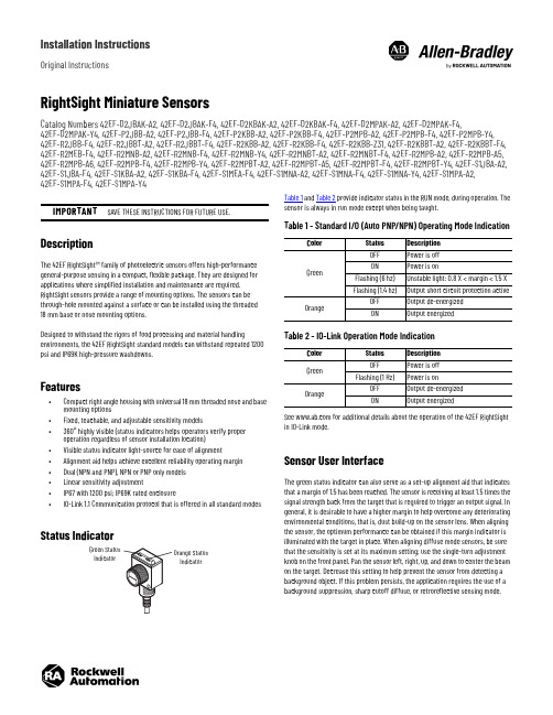
Installation InstructionsOriginal InstructionsRightSight Miniature SensorsCatalog Numbers 42EF-D2JBAK-A2, 42EF-D2JBAK-F4, 42EF-D2KBAK-A2, 42EF-D2KBAK-F4, 42EF-D2MPAK-A2, 42EF-D2MPAK-F4,42EF-D2MPAK-Y4, 42EF-P2JBB-A2, 42EF-P2JBB-F4, 42EF-P2KBB-A2, 42EF-P2KBB-F4, 42EF-P2MPB-A2, 42EF-P2MPB-F4, 42EF-P2MPB-Y4, 42EF-R2JBB-F4, 42EF-R2JBBT-A2, 42EF-R2JBBT-F4, 42EF-R2KBB-A2, 42EF-R2KBB-F4, 42EF-R2KBB-Z31, 42EF-R2KBBT-A2, 42EF-R2KBBT-F4, 42EF-R2MEB-F4, 42EF-R2MNB-A2, 42EF-R2MNB-F4, 42EF-R2MNB-Y4, 42EF-R2MNBT-A2, 42EF-R2MNBT-F4, 42EF-R2MPB-A2, 42EF-R2MPB-A5, 42EF-R2MPB-A6, 42EF-R2MPB-F4, 42EF-R2MPB-Y4, 42EF-R2MPBT-A2, 42EF-R2MPBT-A5, 42EF-R2MPBT-F4, 42EF-R2MPBT-Y4, 42EF-S1JBA-A2, 42EF-S1JBA-F4, 42EF-S1KBA-A2, 42EF-S1KBA-F4, 42EF-S1MEA-F4, 42EF-S1MNA-A2, 42EF-S1MNA-F4, 42EF-S1MNA-Y4, 42EF-S1MPA-A2, 42EF-S1MPA-F4, 42EF-S1MPA-Y4DescriptionThe 42EF RightSight™ family of photoelectric sensors offers high-performance general-purpose sensing in a compact, flexible package. They are designed for applications where simplified installation and maintenance are required. RightSight sensors provide a range of mounting options. The sensors can be through-hole mounted against a surface or can be installed using the threaded 18mm base or nose mounting options.Designed to withstand the rigors of food processing and material handlingenvironments, the 42EF RightSight standard models can withstand repeated 1200 psi and IP69K high-pressure washdowns.Features•Compact right angle housing with universal 18 mm threaded nose and base mounting options•Fixed, teachable, and adjustable sensitivity models•360° highly visible (status indicators helps operators verify proper operation regardless of sensor installation location)•Visible status indicator light-source for ease of alignment•Alignment aid helps achieve excellent reliability operating margin •Dual (NPN and PNP), NPN or PNP only models •Linear sensitivity adjustment•IP67 with 1200 psi; IP69K rated enclosure•IO-Link 1.1 Communication protocol that is offered in all standard modesStatus IndicatorTable 1 and Table 2 provide indicator status in the RUN mode, during operation. The sensor is always in run mode except when being taught.See for additional details about the operation of the 42EF RightSight in IO-Link mode.Sensor User InterfaceThe green status indicator can also serve as a set-up alignment aid that indicates that a margin of 1.5 has been reached. The sensor is receiving at least 1.5 times the signal strength back from the target that is required to trigger an output signal. In general, it is desirable to have a higher margin to help overcome any deteriorating environmental conditions, that is, dust build-up on the sensor lens. When aligning the sensor, the optimum performance can be obtained if this margin indicator is illuminated with the target in place. When aligning diffuse mode sensors, be sure that the sensitivity is set at its maximum setting; use the single-turn adjustment knob on the front panel. Pan the sensor left, right, up, and down to center the beam on the target. Decrease this setting to help prevent the sensor from detecting a background object. If this problem persists, the application requires the use of a background suppression, sharp cutoff diffuse, or retroreflective sensing mode.IMPORTANTSAVE THESE INSTRUCTIONS FOR FUTURE USE.IndicatorIndicatorTable 1 - Standard I/O (Auto PNP/NPN) Operating Mode IndicationColorStatus Description GreenOFF Power is off ON Power is onFlashing (6 hz)Unstable light: 0.8 X < margin < 1.5 X Flashing (1.4 hz)Output short circuit protection activeOrangeOFF Output de-energized ON Output energizedTable 2 - IO-Link Operation Mode IndicationColor Status Description GreenOFF Power is off Flashing (1 Hz)Power is onOrangeOFF Output de-energized ON Output energized2Rockwell Automation Publication 42EF-IN008B-EN-P - August 2020RightSight Miniature Sensors Installation InstructionsWiring DiagramsThe quick-disconnect connector is shown in the following diagrams. The pin numbers correspond to male connectors on the sensor.Figure 1 - Micro (M12) Male QD on Pigtail and Integral Pico (M8) Male QDOutput WiringFigure 2 - Light Operate PNP and NPN Models(42EF-D2JBAK-x , 42EF-P2JBB-x , 42EF-R2JBB-x , 42EF-S1JBB-x ) (a)Figure 3 - Dark Operate PNP and NPN Models(42EF-D2KBAK-x , 42EF-P2KBB-x , 42EF-R2KBB-x , 42EF-S1KBB-x ) (a)Figure 4 - PNP Complementary Models(42EF-D2MPAK-x , 42EF-P2MPB-x , 42EF-R2MPB-x , 42EF-S1MPB-x ) (a)Figure 5 - NPN Complementary Models(42EF-D2MNAK-x , 42EF-P2MNB-x , 42EF-R2MNB-x , 42EF-S1MNB-x ) (a)The IO-Link output pin 4 (black) does not support the connection of multiple sensors in series (for example, one sensor powering the next sensor). Theconnection of multiple sensors in series can be achieved when using pin 2 (white) outputs or by ordering a non-IO-Link catalog number. See theRockwell Automation® Knowledgebase or contact your local distributor for specific ordering information. For additional information about sensor operation in IO-Link mode, see publication 42EF-UM001.Approximate Dimensions [mm (in.)]Typical Response CurvesFigure 6 - Visible Red Polarized Retroreflective— 3.0 m Margin CurveFigure 7 - Visible Red Diffuse—500 mm Margin Curve(a)Replace the x in the catalog number with a suffix from Table 3.Table 3 - Connection TypesDescription Cat. No. Suffix2 m (6.6 ft) cable-A24-pin DC micro (M12) QD on 150 mm (6 in.) pigtail -F44-pin DC pico (M8) QD on 150 mm (6 in.) pigtail-Y412321M12 MaleM8 Male+V-VBlue (3)Black (4)White (2)Brown (1)PNP light operate or IO-Link NPN light operate or disabled (IO-Link operation default)+V-VBlue (3)Black (4)White (2)Brown (1)PNP dark operate or IO-Link NPN dark operate or disabled (IO-Link operation default)+V-VBlue (3)Black (4)White (2)Brown (1)PNP light operate or IO-Link PNP dark operate or disabled (IO-Link operation default)+V-VBlue (3)Black (4)White (2)Brown (1)NPN light operate or IO-LinkNPN dark operate or disabled (IO-Link operation default)Sensitivity Adjustment (diffuse and glass fiber-110100Distance to Reflector (mm)O p e r a t i n g M a r g i n0.110100011010001001100Distance (mm)M a r g i n (X )Rockwell Automation Publication 42EF-IN008B-EN-P - August 20203RightSight Miniature Sensors Installation InstructionsFigure 8 - Infrared Sharp Cutoff - 130 mm Margin CurveFigure 9 - Visible Red Polarized Retroreflective—3.0 m Beam PatternFigure 10 - Visible Red Diffuse—500 mm Beam PatternFigure 11 - Infrared Sharp Cutoff - 130 mm Beam PatternFigure 12 - Transmitted Beam Receiver—8 m Beam PatternFigure 13 - Transmitted Beam Receiver—Margin CurvesFigure 14 - Transmitted Beam Receiver—20 m Beam PatternAccessories1.010.0100.02.5425.4254Distance (m)O p e r a t i n g M a r g i nDistance (m)B e a m D i a m e t e r (m m )-535-11-3Distance to Target (mm)B e a m D i a m e t e r (m m )-8-6-4-20246812010080604020Distance to Target (mm)B e a m D i a m e t e r (m m )DescriptionCat. No.4-pin DC micro, 2 m (6.5 ft) cordset 889D-F4AC-2Swivel/tilt bracket (see Figure 16)60-2649Straight bracket60-2656Right angle bracket (see Figure 15)60-2657Mounting kit 60-2716Clamp style bracket 871A-BP18Flush mount adaptor60-25904-pin DC micro field-mount terminal chamber871A-TS4-DM 1.25 in. diameter reflector 92-473 in. diameter reflector92-39-0.2-0.15-0.1-0.0500.050.10.150.20.002.004.00 6.008.0010.00Distance (m)B e a m D i a m e t e r (m )1100100011010010Distance (m)O p e r a t i n g M a r g i n-0.5-0.4-0.3-0.2-0.100.10.20.30.40.50510152025Distance (m)B e a m D i a m e t e r (m m )Publication 42EF-IN008B-EN-P - August 2020 | Supersedes Publication 42EF-IN008A-EN-P - January 2016Copyright © 2020 Rockwell Automation, Inc. All rights reserved. Printed in the U.S.A.Rockwell Otomasyon Ticaret A.Ş. Kar Plaza İş Merkezi E Blok Kat:6 34752, İçerenköy, İstanbul, Tel: +90 (216) 5698400 EEE Yönetmeliğine UygundurAllen-Bradley, expanding human possibility, RightSight, and Rockwell Automation are trademarks of Rockwell Automation, Inc.Trademarks not belonging to Rockwell Automation are property of their respective companies.Your comments help us serve your documentation needs better. If you have any suggestions on how to improve our content, complete the form at rok.auto/docfeedback .For technical support, visit rok.auto/support.PN-59564210001372107 Ver 01Waste Electrical and Electronic Equipment (WEEE)Rockwell Automation maintains current product environmental compliance information on its website at rok.auto/pec .At the end of life, this equipment should be collected separately from any unsorted municipal waste.Figure 15 - Right Angle Bracket #60-2657Figure 16 - Swivel/Tilt Bracket #60-2649SpecificationsAttribute 42EF-*J*42EF-*K*42EF-*M*Certifications c-UL-us Listed and CE Marked for all applicable directives Vibration 10…55 Hz, 1 mm (0.04 in.) amplitude, meets or exceeds IEC 60947-5-2Shock 30 G with 1 ms pulse duration, meets or exceeds IEC 60947-5-2Relative humidity 5…95% (noncondensing)Ambient-light immunity •Incandescent light: 5000 lux •Sunlight: 20,000 lux User InterfaceStatus indicators •Green (power and margin)•Orange (output) Electrical Adjustments Fixed or adjustment knob by cat. no.Voltage10…30V DC, I-O link: 18…30V DC Current consumption 30 mA, maxSensor protection False pulse, reverse polarity, overload, short circuit Outputs Response time • 1 ms (diffuse, polarized retroreflective)• 4 ms (transmitted beam)Output type PNP and NPN PNP OR NPN(based on cat. no.)Load current 100 mA Leakage current, max •PNP: 0.1 mA •NPN: 0.3 mA Mechanical Housing material Mindel™Lens material Acrylic Cover material Udel™Supplied accessories 18 mm mounting nutEnvironmental Enclosure type rating NEMA 4X, 6P, IP67, IP69K; 1200 psi (8270 kPa) washdown Operating temperature -25…+70 °C (-13…+158 °F)Connection type•2 m (6.6 ft) cable•4-pin DC micro (M12) QD on 150 mm (5.9 in.) pigtail •4-pin DC pico (M8) QD on 150 mm (5.9 in.) pigtail。
SICK UM系列超声波传感器选型手册(中文版)
400
UM30 - 215 11
200
100
0
3
100
200
UM30-21211_ 350 mm
[mm] 100
200
300
1
400
500
600
700
800
800 400
0
3
400 800
UM30-21311_ 1300 mm
[mm] 400
800
1200
1
1600
2000
2400
2800
3200
1600 800
ø 65 (2.56)
3
T1 D1 D2 T2
4 57 6
1 紧固螺母,截面直径 36mm 2 M12 连接插头 3 调节和显示面板 4 设置键 1 5 LED 1 6 设置键 2 7 LED 2
连接方式,M12,5 针插头
UM30 - 21x 11 3
棕 1 L+ 黑 4 NC 蓝 3M 白 2 QA 灰 5 Sync/Com
UM30 - 21x 11 8
棕 1 L+ 黑 4 q/Q 蓝 3M 白 2 QA 灰 5 Sync/Com
UM30 - 21x 11 1
UM30 - 21x 11 5
棕 1 L+ 黑 4 q/Q 蓝 3M 白 2 NC 灰 5 Sync/Com
UM30-2
UM30 - 21x 11 2 UM30 - 21x 11 4
UM30-2 超声波传感器
UM30 - 212
型号 UM30-212111 UM30-212112 UM30-212118 UM30-212115 UM30-212114 UM30-212113
光电传感器数据手册说明书
DatasheetMiniature self-contained photoelectric sensors in universal housing•Bright, visible red (640 nm) light source•Standard models available with 4-wire 2 m (6.5 ft) or 9 m (30 ft) cable or 3 or 4-wire 150 mm (6 in) pigtail with Pico-style M8 threaded connector•Solid-state, bipolar outputs: one current sourcing (PNP) and one current sinking (NPN) standard on 4-wire models•Single output solid-state PNP or NPN standard on Q3 models •Light Operate (LO) or Dark Operate (DO), depending on model•Models available with PFA chemical-resistant jacket (1200 psi washdown rated)for use in harsh environments•Compact 8 mm (0.31 in) housing mounts almost anywhere•Crosstalk avoidance circuitry for applications with multiple sensors•LED status indicators for Power ON, Output Overload, Signal Received, and Marginal Signal•Advanced ASIC technology makes sensor resistant to optical and electrical noise sourceStandard ModelChemical-ResistantModelWARNING:•Do not use this device for personnel protection•Using this device for personnel protection could result in serious injury or death.•This device does not include the self-checking redundant circuitry necessary to allow its use inpersonnel safety applications. A device failure or malfunction can cause either an energized (on) or de-energized (off) output condition.Chemical-Resistant ModelsWORLD-BEAM ® Q12 Series SensorOriginal Document 119223 Rev. M7 April 2020119223Standard Modelssuffix W/30 to the model number. For example, Q126E W/30.•To order the 150 mm (6 in) cable with a 4-pin M8/Pico-style (M8 threaded) QD model, add the suffix Q to the model number. For example, Q126EQ.•To order the 150 mm (6 in) cable with a 4-pin M12/Euro-style QD model, add the suffix Q5 to the model number. For example Q126EQ5.3Retroreflective range is specified using one model BRT-60X40C retroreflector. Actual sensing range may be more or less than specified, depending upon efficiency and reflective area of the retroreflector(s) used. - Tel: + 1 888 373 6767P/N 119223 Rev. MIndicator Features1 - Amber and green LEDs•Green on: power to sensor is on •Amber on: received signal•Amber flashing: marginal signalChemical-Resistant models: LEDs are visible through translucent PFA jacket. Rated to 1200 psi washdown.WiringEmitters have no connection to black and white.CAUTION: Observe proper ESD precautions (grounding) when connecting QD models.Emitters–+Bipolar Models, Light Operate–+PNP Models, Light OperateNPN Models, Light Operate–+Bipolar Models, Dark Operate–+PNP Models, Dark OperateNPN Models, Dark Operate–+Key1 = Brown2 = White3 = Blue4 = Black3-pin M8/Pico-style Male QD 4-pin M8/Pico-style Male QD 34-pin M12/Euro-style Male QDSpecificationsSupply Voltage and Current10 to 30 V dc (10% maximum ripple) at 20 mA maximum current Sensing Beam640 nm visible redSupply Protection CircuitryProtected against reverse polarity and transient voltagesOutput ConfigurationBipolar (1 NPN and 1 PNP) solid-state output or Single output (PNP or NPN), LO or DO, depending on model Repeatability125 microseconds Switching FrequencyOpposed Mode: 385 Hz LP/LV Mode: 715 Hz FF Mode: 590 HzP/N 119223 Rev. M - Tel: + 1 888 373 67673Output Protection CircuitryProtected against false pulse on power-up, short-circuit protectedOutput Response TimeOpposed Mode: 1.3 ms ON; 900 µs OFF LP/LV Mode: 700 µs ON/OFF FF Mode: 850 µs ON/OFFNOTE: 120 ms delay on power-up; outputs do not conduct during this time.IndicatorsOne Yellow and one Green LED (see Figure 1)ConstructionPolarized Retro Models: Thermoplastic elastomer housing with glass lens All Other Standard Models: Thermoplastic elastomer housing with polycarbonate lensChemical-Resistant Models: Housing encased in PFA jacket; cable encased in 3/16 in O.D. PFA tubing Output RatingsOFF-state leakage current:NPN: 10 µA PNP: 10 µAON-state saturation voltage:NPN: 2 V at 50 mA PNP: 2 V at 50 mAVibration and Mechanical ShockAll models meet MIL-STD-202F, Method 201A (Vibration: 10 Hz to 60 Hz maximum, 0.06 inch (1.52 mm) double amplitude, 10G maximumacceleration) requirements. Also meets IEC 60947-5-2 (Shock: 30G 11 ms duration, half sine wave) requirements.ConnectionsStandard Models: 2 m (6.5 ft) or 9 m (30 ft) attached PVC cable, or 150 mm (6 in) pigtail with M8 or M12 threaded connection, depending on the model orderedChemical-Resistant Models: 2 m (6.5 ft) cable encased in 3/16 in O.D. PFA tubing Environmental RatingStandard Models: IEC IP67Chemical-Resistant Models: IEC IP67 (NEMA6) and PW12 1200 psi washdown per NEMA ICS5, Annex F-2002ConditionsOperating Temperature: –20 °C to +55 °C (–4 °F to +131°F)Storage Temperature: –30 °C to +75 °C (–22 °F to +167 °F)95% at +50 °C maximum relative humidity (non-condensing)Certifications(Chemical-resistant models are not UR/UL approved.)Required Overcurrent ProtectionWARNING: Electrical connections must bemade by qualified personnel in accordance with local and national electrical codes and regulations.Overcurrent protection is required to be provided by end product application per the supplied table.Overcurrent protection may be provided with external fusing or via Current Limiting, Class 2 Power Supply.Supply wiring leads < 24 AWG shall not be spliced.For additional product support, go to .Dimensions15.0 mm 4.7 mm (0.19")Polarized RetroModelsM3 mounting screws included(0.31")12.4 mm (0.49")max. torque 0.9 Nm (8 in-lbf)Figure 1. Standard Models - Tel: + 1 888 373 6767P/N 119223 Rev. MMounting hardwarenot included2 m (6.5')* When mounting by running a screw throughboth flanges without support between the flanges,Figure 2. Chemical-Resistant ModelsPerformance Curves - Opposed ModePerformance Curves - Retroreflective ModePerformance is based on the use of a model BRT-60X40C retroreflector.P/N 119223 Rev. M - Tel: + 1 888 373 67675Performance Curves - Fixed-FieldFocus and spot sizes are typical. Performance based on use of 90% reflectance white test card.*AccessoriesCordsets - Tel: + 1 888 373 6767P/N 119223 Rev. MBracketsSMBQ12T•Right-angle bracket•20-ga. 300 series stainless steelHole center spacing: A to B = 7.6Hole size: A = 3.5 x 8.1, B=ø 3.2SMBQ12A•Adjustable right-anglebracket•20-ga. 300 series stainless steelHole center spacing: A to B = 7.6Hole size: A = 3.5 x 8.1, B=ø 3.2Sensor Status IndicatorsP/N 119223 Rev. M - Tel: + 1 888 373 67677AperturesOpposed-mode sensors (standard models only) may be fitted with apertures to narrow or shape the sensor’s effective beam to more closely match the size or profile of the objects being sensed. A common example is the use of “line” (or “slot”) type apertures to sense thread.Note: The use of apertures will reduce the sensing range (see table below).Banner Engineering Corp. Limited WarrantyBanner Engineering Corp. warrants its products to be free from defects in material and workmanship for one year following the date of shipment. Banner Engineering Corp. will repair or replace, free of charge, any product of its manufacture which, at the time it is returned to the factory, is found to have been defective during the warranty period. This warranty does not cover damage or liability for misuse, abuse, or the improper application or installation of the Banner product.THIS LIMITED WARRANTY IS EXCLUSIVE AND IN LIEU OF ALL OTHER WARRANTIES WHETHER EXPRESS OR IMPLIED (INCLUDING, WITHOUT LIMITATION, ANY WARRANTY OF MERCHANTABILITY OR FITNESS FOR A PARTICULAR PURPOSE), AND WHETHER ARISING UNDER COURSE OF PERFORMANCE, COURSE OF DEALING OR TRADE USAGE.This Warranty is exclusive and limited to repair or, at the discretion of Banner Engineering Corp., replacement. IN NO EVENT SHALL BANNER ENGINEERING CORP. BE LIABLE TO BUYER OR ANY OTHER PERSON OR ENTITY FOR ANY EXTRA COSTS, EXPENSES, LOSSES, LOSS OF PROFITS, OR ANY INCIDENTAL, CONSEQUENTIAL OR SPECIAL DAMAGES RESULTING FROM ANY PRODUCT DEFECT OR FROM THE USE OR INABILITY TO USE THE PRODUCT, WHETHER ARISING IN CONTRACT OR WARRANTY, STATUTE, TORT, STRICT LIABILITY, NEGLIGENCE, OR OTHERWISE.Banner Engineering Corp. reserves the right to change, modify or improve the design of the product without assuming any obligations or liabilities relating to any product previously manufactured by Banner Engineering Corp. Any misuse, abuse, or improper application or installation of this product or use of the product for personal protection applications when the product is identified as not intended for such purposes will void the product warranty. Any modifications to this product without prior express approval by Banner Engineering Corp will void the product warranties. All specifications published in this document are subject to change; Banner reserves the right to modify product specifications or update documentation at any time. Specifications and product information in English supersede that which is provided in any other language. For the most recent version of any documentation, refer to:.For patent information, see /patents.FCC Part 15 and CAN ICES-3 (B)/NMB-3(B)This device complies with part 15 of the FCC Rules and CAN ICES-3 (B)/NMB-3(B). Operation is subject to the following two conditions:1.This device may not cause harmful interference, and2.This device must accept any interference received, including interference that may cause undesired operation.This equipment has been tested and found to comply with the limits for a Class B digital device, pursuant to part 15 of the FCC Rules and CAN ICES-3 (B)/NMB-3(B). These limits are designed to provide reasonable protection against harmful interference in a residential installation. This equipment generates, uses and can radiate radio frequency energy and, if not installed and used in accordance with the instructions, may cause harmful interference to radio communications. However, there is no guarantee that interference will not occur in a particular installation. If this equipment does cause harmful interference to radio or television reception, which can be determined by turning the equipment off and on, the user is encouraged to try to correct the interference by one or more of the following measures:•Reorient or relocate the receiving antenna.•Increase the separation between the equipment and receiver.•Connect the equipment into an outlet on a circuit different from that to which the receiver is connected.•Consult the manufacturer.© Banner Engineering Corp. All rights reserved。
高性能光电传感器数据手册说明书
Datasheet•Advanced one-piece photoelectric sensors with outstanding optical performance and extremely rugged design•90 V AC to 250 V AC•Protected solid-state relay output; 300 mA maximum load at up to 250 V AC•Multiple sensing modes include: opposed, diffuse, retroreflective and convergent, plus glass and plastic fiber optic models •Selectable light/dark operate•Versatile plug-in modules available for output timing logic and/or signal strength display •Highly visible Power, Signal (AID ™ System 1), and Output indicator LEDs•Choice of prewired 2 m (6.5 ft) or 9 m (30 ft) unterminated cable, plus Mini-style or Micro-style quick-disconnect fittings •Versatile mounting options•Designed to withstand 1200 psi washdown; exceeds its NEMA 6P and IEC IP67 ratingWARNING:•Do not use this device for personnel protection•Using this device for personnel protection could result in serious injury or death.•This device does not include the self-checking redundant circuitry necessary to allow its use inpersonnel safety applications. A device failure or malfunction can cause either an energized (on) or de-energized (off) output condition.ModelsTo order the 9 m (30 ft) PVC cable model, add the suffix "W/30" to the cabled model number. For example, Q452E W/30. A model with a quick disconnect (QD) connector requires a mating cable.Opposed-Mode Emitter (E) and Receiver (R) ModelsBecause of their extremely high excess gain, these opposed-mode sensors are an excellent option for sensing in contaminated or dirty areas, and are also the best choice for long-range sensing. Sensingbeam: Infrared, 880 nmRetroreflective-Mode ModelsThe visible red sensing beam of these sensors makes them very easy to align. Model Q45BW22LP polarizes the emitted light and filters out unwanted reflections, makingsensing possible in applications otherwise considered unsuited to retroreflective sensing.Performance is specified using the model BRT-3 3-inch reflector (go to for more information). Sensing beam: Visible red, 680 nmQ45BW22 Series SensorOriginal Document 37209 Rev. G30 January 202037209Diffuse-Mode ModelsThese diffuse-mode models detect objects by sensing the reflection of their own emitted light.Ideal for use when the reflectivity and profile of the object to be sensed are sufficient to return alarge percentage of emitted light back to the sensor. Model Q45BW22DX is the first choice fordiffuse-mode applications when there are no background objects to falsely return light. Sensingbeam: Infrared, 880 nmConvergent-Mode ModelsThese sensors are ideal for reflective sensing of very small parts or profiles, and can accurately sensethe position of parts approaching from the side. Ignores all but highly reflective objects that are outsideof the sensing range. Sensing beam: Visible red, 680 nm - Tel: + 1 888 373 6767P/N 37209 Rev. GGlass Fiber-Optic ModelsThese models are an excellent choice for glass fiber optic applications where faster sensor response is not important. Their high excess gain means that opposed individual fibers can operate reliably in many very hostileenvironments. Also, special miniature bifurcated fiber optic assemblies with bundle sizes as small as 0.5 mm (0.020 in) dia. may be used successfully for diffuse-mode sensing when using sensor model Q45BW22F(Q). For more information on compatible glass fiber optics, go to .Plastic Fiber-Optic ModelsLower in cost than glass fiber optics, plastic fiber optics are ideal for use in situations whereenvironmental conditions allow (for example, low levels of acids, alkalis, and solvents). Most are easily cut to length in the field, and are available in a variety of sensing end styles. For more information on compatible plastic fiber optics, go to . Sensing beam: Visible red, 660 nmOverviewStatus indicator LEDs for power, signal, and output are clearly visible beneath a raised dome in the sensor’s transparent o-ring-sealed polycarbonate cover. Also located beneath the sensor’s o-ring-sealed cover are controls for light/dark operate selection and the sensitivity adjustment.•The power indicator (green) lights when power is applied to the sensor.•The signal indicator (red) lights when the sensor sees its modulated light source and pulses at a rate proportional to the strength of the received light signal; this is the AID ™ Alignment Indicating Device 2.•The output indicator (amber) lights when the sensor’s output is conducting. This indicator is especially useful when a timing logic module is used and signal and output conditions are not concurrent.1.LEDs•Green LED: Power on indicator •Red LED: Signal indicator•Amber LED: Output status indicator 2.Optional LED signal strength display 3.Optional timing adjustment 4.Optional timing adjustment 5.Light/dark operate switchP/N 37209 Rev. G - Tel: + 1 888 373 67673Wiring Diagram–+bn (1)bu (3)90–250 V AC1 = Brown 3 = Blue4 = Black1 = Red and black2 = Red and white3 = Red4 = GreenSpecificationsSupply Voltage and Current90 V AC to 250 V AC (50 to 60 Hz)Average current: 20 mAPeak current: 500 mA at 120 V AC, 750 mA at 250 V AC Supply Protection CircuitryProtected against transient voltagesOutput ConfigurationShort circuit/overload protected FET solid-state relayRepeatabilityOpposed mode: 0.25 millisecondsAll other sensing modes: 0.5 millisecondsResponse time and repeatability specifications are independent of signal strength.AdjustmentsLocated under the sensor’s transparent cover: Light/Dark Operate select switch; and multi-turn Sensitivity control (allows precise sensitivity setting—turn clockwise to increase gain). Optional logic and logic/display modules have adjustable timing functions. - Tel: + 1 888 373 6767P/N 37209 Rev. GOutput RatingContinuous current: 300 mA max. to 50 °C (derate to 200 mA at 70 °C, 5mA/°C)Inrush current: 3 A maximum for 100 milliseconds, 5 A maximum for 1millisecondOff-state leakage current: <100 microamps Saturation voltage: <3 V at 200 mA Output Protection CircuitryManually-resettable output latch-out trips in the event of an output overload or short circuit condition. The green Power LED flashes to indicate the latch-out. To reset the output, remove power to the sensor and load for 5seconds, then restore power.Output Response TimeOpposed mode: 2 milliseconds ON, 1 millisecond OFF All other sensing modes: 2 milliseconds ON/OFFNote: 100 millisecond delay on power-up.Output is non-conducting during this time.Required Overcurrent ProtectionWARNING: Electrical connections must bemade by qualified personnel in accordance with local and national electrical codes and regulations.Overcurrent protection is required to be provided by end product application per the supplied table.Overcurrent protection may be provided with external fusing or via Current Limiting, Class 2 Power Supply.Supply wiring leads < 24 AWG shall not be spliced.For additional product support, go to .ConstructionMolded reinforced thermoplastic polyester housing, o-ring-sealedtransparent polycarbonate cover, molded acrylic lenses, and stainless steel hardware. Q45s are designed to withstand 1200 psi washdown. The base of cabled models has a 1/2-in NPS integral internal conduit thread.IndicatorsIndicator LEDs are clearly visible beneath a raised transparent polycarbonate dome on top of the sensor.Power (green) LED: Lights whenever 90 V ac to 250 V ac power is applied,and flashes to indicate output overload or output short circuitSignal (red) AID ™ System LED: Lights whenever the sensor sees itsmodulated light source, and pulses at a rate proportional to the strength of the received light signalLoad (amber) LED: Lights whenever the output relay is energized Optional 7-element LED: Signal strength display module Environmental Rating NEMA 6P, IEC IP67ConnectionsPVC-jacketed 2 m (6.5 ft) or 9 m (30 ft) cables, or 3-pin Mini-style (“Q” suffix models) or 4-pin Micro-style (“Q1” suffix models) quick-disconnect (QD)fittings are available. QD cables are ordered separately.Operating Conditions–40 °C to +70 °C (–40 °F to +158 °F)90% at +50 °C maximum relative humidity (non-condensing)Application NotesOptional output timing modules are available.CertificationsDimensions2m (6.5') CableExternal thread (M30 x 1.5)hex nut suppliedQD ConnectorP/N 37209 Rev. G - Tel: + 1 888 373 67675Performance CurvesDiffuse-mode performance curves are based on a 90% reflectance white test card. - Tel: + 1 888 373 6767P/N 37209 Rev. Gwhite test card.Convergent mode performance curves are based on a 90% reflectanceP/N 37209 Rev. G - Tel: + 1 888 373 67677Plastic fiber optic Diffuse mode performance curves are based on a 90% reflectancewhite test card.AccessoriesCordsets - Tel: + 1 888 373 6767P/N 37209 Rev. GRetroreflective TargetsBanner offers a wide selection of high-quality retroreflective targets. See for complete information.Note: Polarized sensors require corner cube typeretroreflective targets. Non-polarized sensors may use any retroreflective target.BracketsOutput Timing Logic and Signal Strength Display ModulesQ45 sensors easily accept the addition of output timing logic and signal strength display functions. Display modules have a seven-element display that gives a more precise indication of excess gain than does the AID ™ system LED that is standard on Q45sensors. The modules listed below may be used with all Q45BW22 sensors. Refer to the module's datasheet for more information.P/N 37209 Rev. G - Tel: + 1 888 373 67679Banner Engineering Corp. Limited WarrantyBanner Engineering Corp. warrants its products to be free from defects in material and workmanship for one year following the date of shipment. Banner Engineering Corp. will repair or replace, free of charge, any product of its manufacture which, at the time it is returned to the factory, is found to have been defective during the warranty period. This warranty does not cover damage or liability for misuse, abuse, or the improper application or installation of the Banner product.THIS LIMITED WARRANTY IS EXCLUSIVE AND IN LIEU OF ALL OTHER WARRANTIES WHETHER EXPRESS OR IMPLIED (INCLUDING, WITHOUT LIMITATION, ANY WARRANTY OF MERCHANTABILITY OR FITNESS FOR A PARTICULAR PURPOSE), AND WHETHER ARISING UNDER COURSE OF PERFORMANCE, COURSE OF DEALING OR TRADE USAGE. This Warranty is exclusive and limited to repair or, at the discretion of Banner Engineering Corp., replacement. IN NO EVENT SHALL BANNER ENGINEERING CORP. BE LIABLE TO BUYER OR ANY OTHER PERSON OR ENTITY FOR ANY EXTRA COSTS, EXPENSES, LOSSES, LOSS OF PROFITS, OR ANY INCIDENTAL, CONSEQUENTIAL OR SPECIAL DAMAGES RESULTING FROM ANY PRODUCT DEFECT OR FROM THE USE OR INABILITY TO USE THE PRODUCT, WHETHER ARISING IN CONTRACT OR WARRANTY, STATUTE, TORT, STRICT LIABILITY, NEGLIGENCE, OR OTHERWISE.Banner Engineering Corp. reserves the right to change, modify or improve the design of the product without assuming any obligations or liabilities relating to any product previously manufactured by Banner Engineering Corp. Any misuse, abuse, or improper application or installation of this product or use of the product for personal protection applications when the product is identified as not intended for such purposes will void the product warranty. Any modifications to this product without prior express approval by Banner Engineering Corp will void the product warranties. All specifications published in this document are subject to change; Banner reserves the right to modify product specifications or update documentation at any time. Specifications and product information in English supersede that which is provided in any other language. For the most recent version of any documentation, refer to: .For patent information, see /patents.© Banner Engineering Corp. All rights reserved。
光电传感器快速参考指南家族概述说明书
in catalog)
UL Listed C-UL Listed CE
UL Listed C-UL Listed CE
Proximity Sensors Quick Reference Guide
Family E57P, PS
iProx Series
E57G Series E57 2 Wire sensors
E51 Series, Modular Limit Switch Style
This versatile sensing family features modular construction, a variety of operating modes and a familiar limit switch style housing.
• Thru-Beam: 20 ft. • Reflex: 15 ft. • Polarized Reflex: 10 ft. • Diffuse Reflective: 8 in. • Glass Fiber Optic: range varies with fiber
DC-only: 10 – 30V AC/DC: 20 – 132V AC, 15 – 30V DC
DC-only: 600 mA
AC-only: 1.0 A
NEMA 3, 3S, 4, 4X, 6, 6P and 13; Class I, II, III, Division 2, Groups A, B, C, D, F and G (conduit entry only)
- 1、下载文档前请自行甄别文档内容的完整性,平台不提供额外的编辑、内容补充、找答案等附加服务。
- 2、"仅部分预览"的文档,不可在线预览部分如存在完整性等问题,可反馈申请退款(可完整预览的文档不适用该条件!)。
- 3、如文档侵犯您的权益,请联系客服反馈,我们会尽快为您处理(人工客服工作时间:9:00-18:30)。
G6经济型迷你光电开关德国西克传感器产品简介2 S I C K超越标准 - G6易于对准经济型迷你光电开关3w w w.s i c k.c o m/g lo b al s en so r片技术S I C K4 S I C KGTB6L+M QL+MQ NC漫反射式光电开关,背景遮蔽型LED光源技术,光点更亮更精确 金属螺纹安装孔,安装简便且坚固 大旋钮方便调节 指示灯大而明亮类激光性能施克 芯片,抗环境干扰和传感器互相干扰ASIC 光轴接收光轴发射所有尺寸均为毫米(英寸)G6S I C K5252010501550(1.97)mm(inch)100(3.94)150(5.91)200(7.87)250(9.84)300(11.81)Ø 6.6Ø 5.6Ø 5.3(5.91)(9.84)(1.97)(7.87)(3.94)(11.81)18 % 90 %2 6 %311)对90%反射率物体(基于DIN 5033的标准白色)2) T a=+25°C下平均工作时间100,000小时3)限定值,电源极性反接在短路保护下电流最大8A4) 不可以超出供电电压Vs允许范围值信号冗余最大典型检测范围检测距离对白色( 的反射率)的检测距离对灰色( 的反射率)的检测距离对黑色( 的反射率)的检测距离5) 空载8) 0°C以下不可弯曲6)电阻性负载情况下信号传输时间7) 亮/暗比例1:1所有尺寸均为毫米(英寸)距离单位为毫米(英寸)距离单位为毫米(英寸)6 S I C KL+M Q所有尺寸均为毫米(英寸)LED光源技术,光点更亮更精确 金属螺纹安装孔,安装简便且坚固施克ASIC芯片,抗环境光干扰和传感器互相干扰 大旋钮方便调节 指示灯大而明亮光轴接收光轴发射L+M Q NC反射式光电开关,增强型漫类激光性能GTE6G6S I C K 71)对90%反射率物体(基于DIN 5033的标准白色)2) T a=+25°C下平均工作时间100,000小时3)限定值,电源极性反接在短路保护下电流最大8A4) 不可以超出供电电压Vs允许范围值检测范围1000101信号冗余mm(inch)50(1.9)100(3.9)150(5.9)200(7.9)250(9.8)300(11.8)215) 空载8) 0°C以下不可弯曲6)电阻性负载情况下信号传输时间7) 亮/暗比例1:1最大典型检测距离距离[mm]8 S I C KGL6镜反射式光电开关金属螺纹安装孔,安装简便且坚固 施克ASIC芯片,抗环境光干扰和传感器互相干扰 大旋钮方便调节指示灯大而明亮L+M Q所有尺寸均为毫米(英寸)L+M Q NC光轴接收光轴发射M3螺纹安装孔LED光源技术,光点更亮更精确G6S I C K 9(inch)(78.7)(157.5)(236.2)(315.0)1) Ta=+25°C下平均工作时间100,000小时2)限定值,电源极性反接在短路保护下电流最大8A 3) 不可以超出供电电压Vs允许范围值4)空载5) 电阻性负载情况下信号传输时间6) 亮/暗比例1:17) 0°C以下不可弯曲检测范围 (EGR: 2)[m]GL6镜反射式光电开关,可调节灵敏度检测距离 6 m镜反射式光电开关尺寸图所有型号调节+–4针,M81L+M Q34棕色蓝色黑色3 x 0.14 mm 2连接类型GL6-P4211GL6-N4211GL6-P1211GL6-P1212GL6-N1211GL6-N1212附件电缆和接头安装附件反射镜所有尺寸均为毫米(英寸)1L+M Q NC342棕色蓝色黑色白色光轴接收器光轴发射器M3螺纹安装孔绿色LED 指示灯,电源黄色LED 指示灯,接收光线亮通/暗通旋钮: L = 亮通D = 暗通接收器灵敏度调节器①②③④⑤⑥⑦PinPoint LED 光源技术,光点更亮更精确金属螺纹安装孔,安装简便且坚固SICK ASIC 芯片,抗环境光干扰和传感器互相干扰可通过270°电位计调节接收器灵敏度适用于特殊表面和光亮物体7.6(0.30)9.7(0.38)18.3(0.72)21 (0.83)11.4(0.45)31.5 (1.24)28.5 (1.12)25.4 (1.00)0.5 (0.02)0.5 (0.02)9.7(0.38)3 (0.12)L D12(0.47)S I C K10G6S I C K 11信号冗余Ø 8 mmØ 25 mmØ 80 mmØ 130 mm距离(米)传感器3.05.01.00.351)TA = +25°C 时,平均工作时间100000小时2) 限定值,短路保护下的最大电流为8 A 3)不得超出供电电压V S 的允许范围值4) 空载5)V S > 24 V 或环境温度大于49 °C 时,最大电流I A = 50 mA6) 电阻负载下的信号传输时间7) 亮/暗比例为1:18) 低于0 °C 时不可弯曲最大检测距离6 m 检测范围 5 m接收器灵敏度调节器270°电位计配套装置 PL80A 反射镜光源类型LED 红光,650 nm 1) 光点直径8 mm ,距离350 mm 处偏光滤镜 供电电压V S 10 ... 30 V DC 2)残余纹波 ± 10 % 3) 能耗 ≤ 30 mA 4)开关输出 NPN :集电极开路:QPNP: QPNP 高/低输出电压V S – (≤ 3 V)/约0 V NPN 高/低输出电压约V S /≤ 3 V 输出方式 亮通/暗通旋钮最大输出电流I A 100 mA 5)响应时间 < 625 µs 6)切换频率典型值为1 kHz 7)连接方式电缆,PVC ,2 m 8)M8接头,4针防护等级电流保护电源极性反接保护输入输出短路保护输出过流保护防护等级IP 67环境温度工作温度 –25 °C ... +55 °C储存温度 –40 °C ... +70 °C 重量 M8接头型,约20 g2 m 电缆型,约60 g 外壳材质ABS, PC, PMMA随附配件P250反射镜,安装支架N1211技术数据GL6-N1212N4211P1211P1212P4211检测距离和信号冗余型号Part no.GL6-P1211GL6-P1212GL6-P4211GL6-N1211GL6-N1212GL6-N4211105992210608151059241105992310608141059631订货信息REF-IRF-56型反射镜PL20A 型反射镜P250型反射镜PL40A 型反射镜PL80A 型反射镜反射镜型号 检测范围0.25 ... 1.6 m0.07 ... 2.2 m 0.07 ... 3.5m 0.07 ... 3.8 m 0.07 ... 5.0 m 订货号检测范围最大检测距离距离单位为米(英寸)距离单位为米(英寸)最大检测距离检测范围12GL6G 镜反射式光电开关检测距离6 m镜反射式光电开关尺寸图所有型号调节4针,M81L+M Q34棕色蓝色黑色3 x 0.14 mm 2连接类型GL6G-P4211GL6G-P4212GL6G-N4211GL6G-N4212GL6G-P1211GL6G-P1212GL6G-N1211GL6G-N1212附件电缆和接头安装附件反射镜7.6(0.30)9.7(0.38)18.3(0.72)21 (0.83)11.4(0.45)31.5 (1.24)28.5 (1.12)25.4 (1.00)0.5 (0.02)0.5 (0.02)9.7(0.38)3 (0.12)L D12(0.47)所有尺寸均为毫米(英寸)1L+M Q NC342棕色蓝色黑色白色光轴接收器光轴发射器M3螺纹安装孔绿色LED 指示灯,电源黄色LED 指示灯,接收光线亮通/暗通旋钮: L = 亮通D = 暗通接收器灵敏度调节器+–PinPoint LED 光源技术,光点更亮更精确金属螺纹安装孔,安装简便且坚固SICK ASIC 芯片,抗环境光干扰和传感器互相干扰可通过270°电位计调节接收器灵敏度适用于特殊表面和光亮物体①②③④⑤⑥⑦S I C KG6S I C K 13信号冗余Ø 8 mmØ 25 mmØ 80 mmØ 130 mm距离(米)3.05.01.00.351)T A = +25 °C 时,平均工作时间100000小时2) 限定值,短路保护下的最大电流为8 A 3) 不得超出供电电压V S 的允许范围值4) 空载5)最小光束衰减为20%6) V S > 24 V 或环境温度大于49 °C 时,最大电流I A = 50 mA7) 电阻负载下的信号传输时间8) 亮/暗比例为1:19)低于0 °C 时不可弯曲10) 温度需稳定在±10 °C 范围内最大检测距离 6 m 检测范围 5 m接收器灵敏度调节器270°电位计配套装置 PL80A 反射镜光源类型 LED 红光,650 nm 1) 光点直径 8 mm ,距离350 mm 偏光滤镜 供电电压V S 10 ... 30 V DC 2)残余纹波 ± 10 % 3)能耗 ≤ 30 mA 4)开关输出 NPN :集电极开路:QPNP: Q 光束衰减 > 20%特殊设计 适用于透明物体 5)PNP 高/低输出电压V S – (≤ 3 V)/约0 V NPN 高/低输出电压约V S /≤ 3 V 输出方式 亮通/暗通旋钮最大输出电流I A 100 mA 6)响应时间 < 625 µs 7)切换频率典型值为1 kHz 8) 连接方式电缆,PVC ,2 m 9)M8接头,4针防护等级电流保护电源极性反接保护输入输出短路保护输出过流保护防护等级IP 67环境温度T A 工作温度 –25 °C ... +55 °C 10)储存温度 –40 °C ... +70 °C 重量 M8接头型,约20 g2 m 电缆型,约60 g 外壳材质ABS, PC, PMMA随附配件P250反射镜,安装支架N1211技术数据GL6G-N1212N4211N4212P1211P1212P4211P4212检测距离和信号冗余型号订货号GL6G-P1211GL6G-P1212GL6G-P4211GL6G-P4212GL6G-N1211GL6G-N1212GL6G-N4211GL6G-N421210599241060812105963210608101059925106081110596331060809订货信息REF-IRF-56型反射镜PL20A 型反射镜P250型反射镜PL40A 型反射镜PL80A 型反射镜反射镜型号 检测范围0.25 ... 1.6 m0.07 ... 2.2 m 0.07 ... 3.5m 0.07 ... 3.8 m 0.07 ... 5.0 m检测范围最大检测距离距离单位为米(英寸)距离单位为米(英寸)最大检测距离检测范围传感器S I C KL+M QL+MQ NC射式光电开关对 LED光源技术,光点更亮更精确 金属螺纹安装孔,安装简便且坚固 大旋钮方便调节 指示灯大而明亮类激光性能光轴接收光轴发射所有尺寸均为毫米(英寸)GSE610G6S I C K 111,000100101(inch)(157.48)(472.44)(314.96)(629.92)[m]信号冗余检测范围1) Ta=+25°C下平均工作时间100,000小时2)限定值,电源极性反接在短路保护下电流最大8A 3) 不可以超出供电电压Vs允许范围值4)空载5) 电阻性负载情况下信号传输时间6) 亮/暗比例1:17) 0°C以下不可弯曲最大典型检测距离距离电缆和插头/安装附件Ø9.8(.4)8.2Ø9.81)使用过程中最小弯曲半径R min = 20 x 电缆直径所有尺寸均为毫米(英寸)所有尺寸均为毫米(英寸)所有尺寸均为毫米(英寸)所有尺寸均为毫米(英寸)Ø9.8(.4)8.2Ø9.81)使用过程中最小弯曲半径R min = 20 x 电缆直径12S I C KS I C K13附件L1412All dimensions in mm (inch)所有尺寸均为毫米(英寸)所有尺寸均为毫米(英寸)锁紧螺丝反射镜14 S I C K1)发货包含 GL6 标准型号S I C K15附件完善的服务领先的技术独特的产品SICK 概览SICK CHINA| 客户服务专线: 4000-121-0008014182/2013-09-09中文译本 内容如有变更,恕不另行通知SICK 是一家世界顶级的传感器技术提供商,在全球建立了接近50个子公司和众多的销售机构, 雇员总数超过6,300人。