W45紧凑型光电开关选型手册(中文版)
Omron光电传感器选型指南说明书
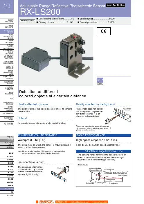
HUMAN MACHINEINTERFACESENERGYMANAGEMENTSOLUTIONSFA COMPONENTSMACHINE VISIONSYSTEMSUV CURINGSYSTEMSCX-400CY-100EX-10EX-20EX-30EX-40CX-440EQ-30EQ-500MQ-WRXRT-610Hardly affected by colorThe color or size of the object does not affect its sensingperformance.Hardly affected by backgroundThe sensor does not detectthe background beyond theset distance since it is ofdistance adjustable type.RobustIts robust enclosure is made of die-cast zinc alloy.High-speed response time: 1 msIt can be used on a high speed assembly line.BASIC PERFORMANCEWaterproof IP67 (IEC)The equipment on which the sensor is mounted can bewashed without any problem.ENVIRONMENTAL RESISTANCENote: H owever, take care that if it is exposed to water splashesduring operation. It may detect a water drop itself.Insusceptible to dustThe sensing performanceis less affected by dust asit does not depend on theincident light intensity.has a specular surface.Adjustable Range Reflective Photoelectric SensorRX-LS200344FIBER SENSORSLASER SENSORS PHOTO-ELECTRIC SENSORS AREA SENSORS SAFETY LIGHT CURTAINS /SAFETY COMPONENTS PRESSURE / FLOW SENSORS INDUCTIVE PROXIMITY SENSORS PARTICULAR USE SENSORS SENSOR OPTIONS SIMPLE WIRE-SAVING UNITS WIRE-SAVING SYSTEMSMEASURE-MENT SENSORS STATIC CONTROL DEVICES LASER MARKERS PLC HUMAN MACHINE INTERFACES ENERGY MANAGEMENT SOLUTIONS FACOMPONENTS MACHINE VISION SYSTEMSUVCURINGSYSTEMSEX-Z CX-400CY-100EX-10 EX-20EX-30EX-40CX-440EQ-30EQ-500RX RT-6105 m cable length type5 m 16.404 ft cable length type (standard: 3 m 9.843 ft ) is also available for NPN output type.Model No.: RX-LS200-C5Accessory• MS-RX-1 (Sensor mounting bracket)Narrow-view slit mask• OS-RXL-□Protective tubeTwo M4 (length 16 mm 0.630 in )hexagon-socket-head bolts are attached.056 222 38 18*********************SEN TRONIC AG345Adjustable Range Reflective Photoelectric Sensor RX-LS200FIBERSENSORSLASERSENSORSPHOTO-ELECTRICSENSORSAREASENSORSSAFETY LIGHTCURTAINS /SAFETYCOMPONENTSPRESSURE /FLOWSENSORSINDUCTIVEPROXIMITYSENSORSPARTICULARUSESENSORSSENSOROPTIONSSIMPLEWIRE-SAVINGUNITSWIRE-SAVINGSYSTEMSMEASURE-MENTSENSORSSTATICCONTROLDEVICESLASERMARKERSPLCHUMANMACHINEINTERFACESENERGYMANAGEMENTSOLUTIONSFACOMPONENTSMACHINEVISIONSYSTEMSUVCURINGSYSTEMSEX-ZCX-400CY-100EX-10EX-20EX-30EX-40CX-440EQ-30EQ-500RXRT-610I/O circuit diagram Wiring diagramSymbols … D : Reverse supply polarity protection diodeZ D : Surge absorption zener diodeTr : NPN output transistor±10 %RX-LS200NPN output type 056 222 38 18*********************SEN TRONICAGAdjustable Range Reflective Photoelectric SensorRX-LS200346FIBER SENSORS LASER SENSORS PHOTO-ELECTRIC SENSORSAREA SENSORS SAFETY LIGHT CURTAINS /SAFETY COMPONENTS PRESSURE / FLOW SENSORS INDUCTIVE PROXIMITY SENSORS PARTICULAR USE SENSORS SENSOR OPTIONS SIMPLE WIRE-SAVING UNITS WIRE-SAVING SYSTEMSMEASURE-MENT SENSORS STATIC CONTROL DEVICES LASER MARKERS PLC HUMAN MACHINE INTERFACES ENERGY MANAGEMENT SOLUTIONS FACOMPONENTS MACHINE VISION SYSTEMS UVCURINGSYSTEMSEX-Z CX-400CY-100EX-10EX-20EX-30EX-40CX-440EQ-30EQ-500RX RT-610I/O circuit diagramWiring diagramNote: T he output does not incorporate a short-circuit protection circuit.Do not connect it directly to a power supply or a capacitive load.Symbols … D : Reverse supply polarity protection diodeZ D : Surge absorption zener diode Tr : PNP output transistorto 24 V DCSensing fields• Setting distance: 200 mm 7.874 in (Horizontal)• Setting distance: 200 mm 7.874 in (Vertical)• Setting distance: 150 mm 5.906 in (Horizontal)• Setting distance: 150 mm 5.906 in (Vertical)• Setting distance: 150 mm 5.906 in with slit mask (Vertical)• Setting distance: 150 mm 5.906 in with slit mask(Horizontal)0.3940.394Left Center in )S e t t i n g d i s t a n c e L (m m i n Up Center Operating point ℓ (mm in )0.3940.394S e t t i n g d i s t a n c e L (m m in Left Center in)0.1570.157S e t t i n g d i s t a n c e L (m mi nUp Center in )0.1570.157S e t t i n g d i s t a n c e L(m m i nLeft Center Operating point ℓ (mm in )0.1570.157S e t t i n g d i s t a n c e L (m m i nUp Operating point ℓ (mm in )0.1570.157S e t t i n g d i s t a n c e L (m m i nCorrelation between sensing object size and sensing range0.787 1.575 2.362 3.1503.937 in , 7.874 in , each, with white non-glossy 1.969 × 1.969 in ).side length a (mm in )S e n s i n g r a n g e L (m m i n D i s t a n c e L (m m i n RX-LS200-P PNP output type056 222 38 18*********************SEN TRONIC AG347Adjustable Range Reflective Photoelectric Sensor RX-LS200FIBERSENSORSLASERSENSORSPHOTO-ELECTRICSENSORSAREASENSORSSAFETY LIGHTCURTAINS /SAFETYCOMPONENTSPRESSURE /FLOWSENSORSINDUCTIVEPROXIMITYSENSORSPARTICULARUSESENSORSSENSOROPTIONSSIMPLEWIRE-SAVINGUNITSWIRE-SAVINGSYSTEMSMEASURE-MENTSENSORSSTATICCONTROLDEVICESLASERMARKERSPLCHUMANMACHINEINTERFACESENERGYMANAGEMENTSOLUTIONSFACOMPONENTSMACHINEVISIONSYSTEMSUVCURINGSYSTEMSEX-ZCX-400CY-100EX-10EX-20EX-30EX-40CX-440EQ-30EQ-500RXRT-610Correlation between material (50 × 50 mm 1.969 × 1.969 in) and sensing range200 mm 7.874 in100 mm 3.937 in50 mm 1.969 inWhitenon-glossypaperPlywoodCardboardCeramiccircuitboardGraynon-glossypaper(Lightness:3)BlackrubbeMirrorThese bars indicate the sensing rangewith respective objects when thedistance adjuster is set at the sensingrange of 200 mm 7.874 in, 100 mm3.937 in and 50 mm 1.969 in long,each, with white non-glossy paper.(GreenmaskedsurfaceGlassepoxyprintedcircuitboardSensingrangeL(mminWiring• The output of RX-LS200-P does not incorporate a short-circuit protection circuit. Do not connect it directly to apower supply or a capacitive load.Others• Do not use during the initial transient time (50 ms) afterthe power supply is switched on.Mounting• The tightening torque should be 1.17 N·m or less.• Care must be taken regarding the sensor mountingdirection with respect to the object’s direction of movement.Do not make the sensordetect an object in thisdirection because it maycause unstable operation.Sensing object Sensing object Sensing objectintersection of the “ ”mark on the lens faceand the “ ” line.• When detecting a specular object (aluminum or copperfoil) or an object having a glossy surface or coating,please take care that there are cases when the objectmay not be detected due to a small change in angle,wrinkles on the object surface, etc.• When a specular body is present below the sensor, usethe sensor by tilting it slightly upwards to avoid wrongoperation.Use conditions to comply with CE Marking• Following work must be done in case of using thisproduct as a CE marking (European standard EMCDirective) conforming product.Ensure that the shield is connected to 0 V or the actualground.• In case of connecting a sensor to power supply 0 V by usinga shield (piping, etc.)• In case of grounding by using a shield (piping, etc.)Note: The shield (piping, etc.) must be insulated.• If a specular body is present in the background, wrongoperation may be caused due to a small change in theangle of the background body. In that case, install thesensor at an inclination and confirm the operation withthe actual sensing object.• Do not install the sensor at a distance of less than 50 mm1.969 in from the object because the sensing is unstablein this range.Correct Correct Incorrect056 222 38 18*********************SEN TRONICAGAdjustable Range Reflective Photoelectric SensorRX-LS200348FIBER SENSORS LASER SENSORS PHOTO-ELECTRIC SENSORS AREA SENSORSSAFETY LIGHT CURTAINS /SAFETY COMPONENTS PRESSURE / FLOW SENSORSINDUCTIVE PROXIMITY SENSORS PARTICULAR USE SENSORSSENSOR OPTIONS SIMPLE WIRE-SAVING UNITS WIRE-SAVING SYSTEMSMEASURE-MENT SENSORS STATIC CONTROL DEVICES LASER MARKERS PLC HUMAN MACHINE INTERFACES ENERGY MANAGEMENT SOLUTIONS FACOMPONENTS MACHINE VISION SYSTEMSUVCURINGSYSTEMSEX-Z CX-400CY-100EX-10 EX-20EX-30EX-40CX-440EQ-30EQ-500RX RT-610Distance adjustmentSensorRX-LS200 RX-LS200-PProtective tube (Optional)PT-RX500 PT-RX1000MS-RX-1Sensor mounting bracket (Accessory)Assembly dimensions• Follow only steps 1 and 2 respectively. Since the sensing point may change depending on the sensing object, be sure to check the operation with the actual sensing object.<When a sensing object is approaching / moving away from the sensor><When a sensing object moves horizontally to the sensor>) hexagon-socket-AdjustersAdjusting procedure056 222 38 18*********************SEN TRONIC AG。
LM45C中文资料(翻译)
L M45C中文资料(翻译)本页仅作为文档封面,使用时可以删除This document is for reference only-rar21year.MarchLM45系列精密集成电路温度传感器,其输出电压是线性正比于摄氏温度(℃)。
LM45不不需要任何外部校准或微调提供准确在内的政体在室温和G3在G2§C§C在全B20 A100§C温度范围。
低成本保证在晶圆级微调和校准。
LM45的低输出阻抗,线性输出,以及固有的精确校准,尤其是容易读出或控制电路接口。
它可以被用来与一个单一的电源,或具有加号和减号用品。
由于A从它的,它只消耗120米的电源供电,它具有非常低的自加热,小于§C静止空气。
LM45,额定工作超过B20§A100§C温度范围特点?§直接校准摄氏度(℃)?线性 MV /§C标尺因子G3§C的精度保证额定A100全B20§§C范围适合远程应用程序由于低成本晶圆级微调工作电压从至10V漏电流小于120米低的自加热,§C在静止空气中非线性§C最大值在整个温度范围低阻抗输出,1 mA负载20X绝对最大额定值(注1)电源电压±的中输出电压AV 输出电流10毫安贮藏温度B65§CTO A150§C焊接温度SOT封装(注2):气相(60秒)215§?红外(15秒)220注1:绝对最大额定值表明超过这一限度损坏设备可能会发生。
DC和AC电气规范操作时不适用超出其额定工作条件下的设备。
注2:见AN-450“表面安装方法和他们对产品可靠性的影响”一节``表面贴装“在当前国家半导体线性其他方法焊接表面贴装器件的数据手册。
注3:人体模型,通过 K X电阻放电的100 pF的。
机模型,200 pF的每个引脚直接排入。
注4:SOT-23封装的热阻是260§C / W,结到环境连接到印刷电路板,2盎司。
SICK 光电开关-W45 选型
O321SENSICK CATALOGUEWL 27-2n A WS/WE 45through-beam photoelectric switch monitors tear-off on a paper web.m The robust designand large scanning distance are of advantage to the WT 45 photoelectric proximity switch when used to check for tear-off on a paper rolling machine.n Scale, steam andheat in a rolling mill does not affect the WT 45 – here used to detect the pre-sence of steel slabs.v Extreme operating conditions exist insteel making plants – the WT 45 photo-electric proximity switch is ideal for many applications, such as detecting metal sheets before they are wound onto coils.W 45322SENSICK CATALOGUEWT 45 Photoelectric proximity switches, background suppression, infrared light -- DCL+M TENC Q Q0.5 – 12 s 0.015 – 0.3 st 0without time delayt 0without time delay t 3ON-delay when object t 1ON-delay when object enters detection zone enters detection zone t 4OFF-delay when object t 2OFF-delay when object leaves detection zone leaves detection zoneLED signal strength indicatorStandard direction of the material being scanned Centre of optical axis, receiver Centre of optical axis, senderThreaded mounting hole M 6 – 8 mm deep Alignment sightScanning distance adjustment Time adjustmentTime delay selector switch Terminal strip Status indicator11s Robust metal housing s Infrared lightsAdjustable background suppressionsFront lens heating, optionalC ਠ10987654321323SENSICK CATALOGUE WL 27-2WT 45(mm)200016001200800255101520% o f s c a n n i n g d i s t a n c e P 250P 260N 250N 260Scanning distance on black, 6% remission 1Scanning distance on grey, 18% remission11)Average service life 100,000 h at T A = +25 °C 2) Limit values3)May not exceed or fall short of V S tolerances4)Without load5) Signal transit time with resistive load 6)With light/dark ratio 1:18)Up to 140°C with cooling plates (see Accessories)7)A =V S connections reverse-polarityprotectedB =Output Q N and Q P short-circuitprotectedC =Interference pulse suppression200800120016002000324SENSICK CATALOGUEWT 45 Photoelectric proximity switches, background suppression, infrared light -- DCPEL1N0.5 – 12 st 0without time delayt 1ON-delay when object enters detection zone t 2OFF-delay when object leaves detection zoneLED signal strength indicatorStandard direction of the material being scanned Centre of optical axis, receiver Centre of optical axis, senderM 6 threaded mounting hole – 8 mm deep Alignment sightScanning distance adjustment Time adjustmentTime delay selector switchleft: light-switching, right: dark-switching Terminal strip Status indicator11s Robust metal housing s Infrared lightsAdjustable background suppressionsFront lens heating, optional10987654321Cਠ325SENSICK CATALOGUE WL 27-2WT 45(mm)200016001200800255101520% o f s c a n n i n g d i s t a n c e R250R 2601)Average service life 100,000 h at T A = +25°C2)Provide suitable spark suppression for inductive or capacitive loads 3)With light/dark ratio 1:14)A =V S connections reverse-polarityprotectedC =Interference pulse suppression 5)Up to 140°C with cooling plates (see Accessories)200800120016002000Scanning distance on black, 6% remission 1Scanning distance on grey, 18% remission2326SENSICK CATALOGUEWL 45 Photoelectric reflex switches, red light -- DCL+M TEAlarm Q Q Centre of optical axis, sender Centre of optical axis, receiver LED signal strength indicatorM 6 threaded mounting hole – 8 mm deep Alignment sightSensitivity adjustment Time adjustmentTime delay selector switch Terminal strip Status indicators Robust metal housing s Red lights Adjustable sensitivitys Front lens heating, optional sPre-failure signalling output109876543210.5 – 12 s 0.015 – 0.3 st 0without time delayt 0without time delay t 3ON-delay when object t 1ON-delay when object enters detection zone enters detection zone t 4OFF-delay when object t 2OFF-delay when object leaves detection zone leaves detection zoneC ਠ327SENSICK CATALOGUEWL 27-2WL 451001011(m)10100OperatingreserveP250P260N250N2600(m)102030405060s Operating range s Scanning range,max. typical1)Average service life 100,000 hat T A= +25°C2) Limit values3)May not exceed or fall short ofV S tolerances4)Without load5) Signal transit time with resistive load6)With light/dark ratio 1:17) Reference voltage 50 V DC9)Up to 140°C with cooling plates(see Accessories)8)A=V S connections reverse-polarityprotectedB=Output Q N and Q P short-circuitprotectedC=Interference pulse suppression328SENSICK CATALOGUEPEL1NWL 45 Photoelectric reflex switches, red light -- UCCentre of optical axis, sender Centre of optical axis, receiver LED signal strength indicatorM 6 threaded mounting hole – 8 mm deep Alignment sightSensitivity adjustment Time adjustmentTime delay selector switchleft: light-switching, right: dark-switching Terminal strip Status indicators Robust metal housing s Red lights Adjustable sensitivitysFront lens heating, optional10987654321Cਠ0.5 – 12 st 0without time delayt 1ON-delay when object enters detection zone t 2OFF-delay when object leaves detection zone329SENSICK CATALOGUEWL 27-21001011(m)10100Op e r a t i n g r e s e r v e WL 45R 250R 2600(m)102030405060s Operating ranges Scanning range,max. typical1)Average service life 100,000 h at T A = +25°C2)Provide suitable spark suppressionfor inductive or capacitive loads3)With light/dark ratio 1:14)A =V S connections reverse-polarityprotectedC =Interference pulse suppression5)Up to 140°C with cooling plates (see Accessories)6L+MTEL+MAlarmQQCentre of optical axis, sender (WS)Centre of optical axis, receiver (WE)View finder lensLED signal strength indicatorM6 threaded mounting hole – 8 mm deepEyepiece for alignment aidAlignment sightSensitivity adjustmentTime adjustmentTime delay selector switchTerminal stripStatus indicators Robust metal housings Red lights Adjustable sensitivitys Front lens heating, optionals Pre-failure signalling output10119876543210.5 – 12 s0.015 – 0.3 st0without time delayt0without time delayt3ON-delay when object t1ON-delay when objectenters detection zone enters detection zonet4OFF-delay when object t2OFF-delay when objectleaves detection zone leaves detection zone C ਠ100010010110015020025030035040050(m)O p e r a t i n g r e s e r v eP 250P 260N 250N2600(m)50100150200250300350400sOperating rangesScanning range,max. typical1)Average service life 100,000 h at T A = +25 °C 2) Limit values3)May not exceed or fall short of V S tolerances4)Without load5) Signal transit time with resistive load 6)With light/dark ratio 1:18)Up to 140°C with cooling plates (see Accessories)7)A =V S connections reverse-polarityprotectedB =Output Q N and Q P short-circuitprotectedC =Interference pulse suppressionPE L1 N PE L1 NCentre of optical axis, sender (WS)Centre of optical axis, receiver (WE)View finder lensLED signal strength indicatorM6 threaded mounting hole – 8 mm deepEyepiece for alignment aidAlignment sightSensitivity adjustmentTime adjustmentTime delay selector switchleft: light-switching, right: dark-switchingTerminal stripStatus indicators Robust metal housings Red lights Adjustable sensitivitys Front lens heating, optional10119876543210.5 – 12 st0without time delayt1ON-delay when object enters detection zonet2OFF-delay when object leaves detection zone C ਠ100010010110015020025030035040050(m)O p e r a t i n g r e s e r v eR 250R2600(m)50100150200250300350400s Operating ranges Scanning range,max. typical1)Average service life 100,000 h at T A = +25°C2)Provide suitable spark suppression for inductive or capacitive loads3)With light/dark ratio 1:14)A =V S connections reverse-polarityprotectedC =Interference pulse suppression5)Up to 140°C with cooling plates (see Accessories)。
BYW45万能式断路器说明书[应用]
![BYW45万能式断路器说明书[应用]](https://uimg.taocdn.com/4930f8c86394dd88d0d233d4b14e852459fb3957.webp)
BYW45万能式断路器说明书[应用]BYW45万能式路器断用途BYW45万能式路器;以下劳路器,适用于交流断称断50Hz~劳定劳劳400V~劳定劳流劳400A,4000A的配劳劳中。
用分配劳能和保劳劳路~防止劳劳遭受劳劳、欠劳劳、短路、劳劳接地等故障的危害。
路器采用劳子式器~网来断脱扣具有劳劳性保劳功能且劳作劳准重确靠劳精度高。
能避免不必要的停劳~提高供劳可性。
本劳品符合 GB14048.2 《低劳劳劳劳劳和控制劳劳低劳路器断》和IEC 947,2《低劳劳劳劳劳和控制劳劳低劳路器断》等劳准。
劳品型及号其含劳, , , BY W 45附属劳志断路器劳定劳流 (A)断壳路器架等劳断号路器劳劳代万能式路器断企劳代号北京第一低劳劳器有限劳任公司()附属劳志三~抽极劳式~型~BYW45-2000/1600A-M=AC220VX=AC220V; 劳品型描述示例,号QS=AC380V,延劳3s; F=AC220V万能式路器~断壳断架等劳~路器劳定劳流~三抽极劳式~型BYW4520001600AM劳品型描述示例含号劳:劳子器劳定脱扣工作劳源交流~合劳劳磁劳劳定劳劳交流~延劳型欠劳器脱扣=220V=220V劳定劳劳交流~延劳秒劳作~分器劳定劳劳励脱扣交流。
=380V3=220V ? 型式安方装式,固定式、抽劳式操作方式,劳劳机操作、手劳操作极数, 三极极、四器劳劳脱扣,智能型劳子控制器、欠劳瞬劳;或延劳,器和分器。
脱扣励脱扣? 特点劳格品劳劳全万能式路器具有断极极构固定式、抽劳式和三、四劳劳。
劳定劳流劳定劳劳BYW45400、630、800、1000、1250、1600、2000、2500、3200、4000 等劳格.配有面板透明防劳、防劳合劳、罩断抽劳式路器中A抽劳座与断体状离路器本母劳劳、劳劳劳距指示器等附件。
具有劳高的极断限短路分能力和劳定短劳耐受劳流路器采用断和模劳脱扣触装内触触并功能~每相劳安在劳劳小室~劳系劳采用多片劳劳构减型式的劳~劳MCR小了触断断劳系劳的劳性~保劳了路器的高分能力和劳受劳高的短劳耐受劳流。
W24-2紧凑型光电传感器选型手册(中文版)
4.7
87.5
26 15
32
9
30
11.8
27
可调校型号 WT 24-2B 250 WT 24-2V 250
2
65
WT 24-2B 240 WT 24-2B 440 WT 24-2V 540
2
1.0 1.0
10
13 t2
14 t1 15 t1
t0
H 11
D
NPN t2 PNP
t1 + t 2 12
10
测试输入“TE” 发射器关闭
接线方式
VDE保护等级7) 电路保护8) 防护等级
工作环境温度 存储环境温度 重量 前镜加热 外壳材料
1)TA=+25℃叶的平均使用寿命 为100.000小时
2)限定值
WT 24-2 B 210 B 220 B 313 B 410 B 420 V 220 V 510
100...2500mm,可调
1
L+
2
M
3
4
Q/Q
5
TE
3针插头 1 L+ 2M 3 Q/Q
M12.4针插头 1 L+ 3M 4 Q/Q 2 TE
M12.5针插头
1 L+ 3M 4 Q/Q 5 2 TE
技术资料
检测距离
光源种类1) 光点直径
工作电压Vs 残余纹波3) 电流功耗4)
开关输出 最大输出电流 响应时间5) 开关频率6) 预故障信号输出 延时
感
残余纹波3)
<5Vss
器
电流功耗7)
≤50mA
≤70mA,前镜加热
开关输出 最大输出电流 响应时间5) 开关频率6) 预故障信号输出 延时
BAS40-05 丝印45 开关二极管选型手册
0
0.25 0.20 0.15 0.10 0.05 0.00
0
Reverse Characteristics
T =100℃ a
T =25℃ a
10
20
30
40
REVERSE VOLTAGE V (V) R
Power Derating Curve
25
50
75
100
125
AMBIENT TEMPERATURE T (℃) a
【领先的片式无源器件整合供应商—南京南山半导体有限公司】
JIANGSU CHANGJIANG ELECTRONICS TECHNOLOGY CO., LTD
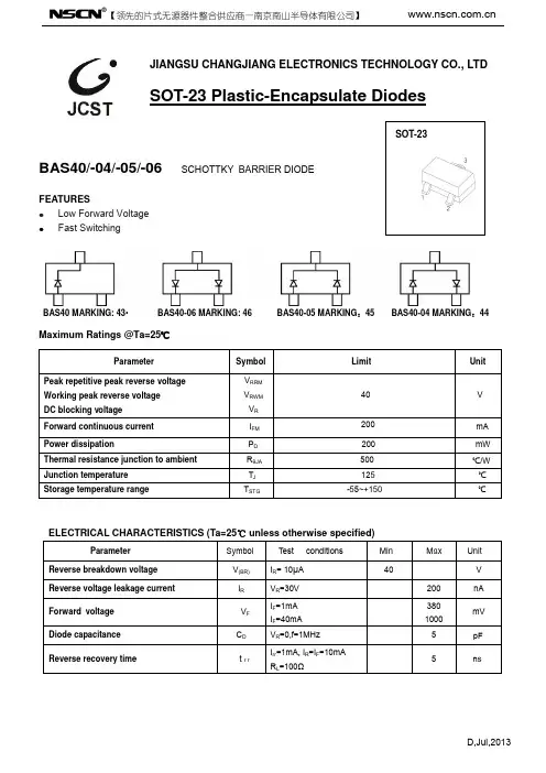
SOT-23 Plastic-Encapsulate Diodes
BAS40/-04/-05/-06 SCHOTTKY BARRIER DIODE
FEATURES z Low Forward Voltage z Fast Switching
SOT-23
BAS40 MARKING: 43•
BAS40-06 MARKING: 46
Maximum Ratings @Ta=25℃
BAS40-05 MARKING:45 BAS40-04 MARKING:44
回访记录
□已联系确认 日期:
□已建议执行 日期:
□未发送但已下单 日期:
□已发送样品 日期:
□客户已签收 日期:
第1页共1页
Symbol
VRRM VRWM
VR IFM PD RθJA TJ TSTG
Limit
40
200 200 500 125 -55~+150
Unit
CFW45系列智能型万能式断路器
2.0Ir1 8.4s
30s 16.9s
60s 32.7s
120s 67.5s
240s
480s
135s
270s
注:2.0Ir1 的时间 I2TL=(1.5Ir1)2tL 计算,其中 tL 为长延时 1.5Ir1 的整定时间,TL 为长延时动作时间。
表4 允差
± 15%
4)短延时过电流保护动作特性见表5
返回
CFW 45 系列智能型万能式断路器
A 断路器
6)智能型脱扣器保护特性出厂整定值见表6
长延时
定值 延时
短延时
定值 延时
瞬时
定值
接地故障
定值 延时
负荷监测
ILC1 ILC2
Ir1 t1(1.5Ir1)
Ir2 t2 Ir3 Ir4 t4
表6 In 15s 8In 0.4s 12In 0.4In OFF(只有显示,不断开) In In
b)通迅波特率最高达 1MHz c)端口遵从 EIA Rs485 协议 d)支持双工、半双工方式 ② 数据传输方式支持 "a)支持串行同步及串行异步方式 b)支持 8 位、9 位为数据传输方式、支持奇偶校验 c)必要时可以实现并行方式通讯 ③ 通讯接口协议 " 分三层:应用层、链路层、物理层;各层协议专用。 ④ 通讯接口的功能 " 主要实现低压配电系统所要求的四遥功能,即:遥控、遥调、遥测、遥讯。
◇ L 型过电流脱扣器的功能 L 型电流脱扣器采用编码开关整定方式,具有过载长延时、短路短延时、瞬时、接地漏电四段保护特
性,以及故障状态、负载电流光柱指示等功能,但无数码显示,功能不及 M 及 H型齐全。供用户在一般 场合下选用。
◆ 断路器的操作性能用操作循环次数表示见表 7
瑞电士光电开关型号说明
瑞电士光电开关型号说明
瑞电士光电开关是一种常用于工业自动化系统中的控制元件。
它可以通过光电
原理实现接通和断开电路信号,在工业生产过程中具有广泛的应用。
以下是几种常见的瑞电士光电开关型号及其说明:
1. 模块型光电开关:该型号具有模块化设计,容易安装和更换。
它可以通过光
电传感器实时检测到物体的存在与否,进而实现电路的开启或关闭。
模块型光电开关通常采用高品质的光电传感器和先进的信号处理技术,具有较高的稳定性和可靠性。
2. 纤细型光电开关:纤细型光电开关适用于对空间要求较高的场所,如狭小的
安装空间或狭窄的通道。
它具有紧凑的外形尺寸和较小的外壳,适合于需要进行精确控制的应用。
纤细型光电开关通常采用红外线或激光作为探测光源,以便实现更高的灵敏度和稳定性。
3. 便携式光电开关:便携式光电开关通常由手持式控制器和无线通讯模块组成。
它可以远程操控和监测远离操作台的设备,适用于一些特殊的工业环境,如高温、高压或有害气体等。
便携式光电开关具有灵活性和可移动性,能够提高工作效率和安全性。
4. 高温型光电开关:高温型光电开关适用于在高温环境下工作的场合。
它采用
耐高温材料和专业密封技术,能够在极端温度条件下正常工作。
高温型光电开关通常能够耐受较高温度范围,保持稳定的性能并提供可靠的控制。
总之,瑞电士光电开关的不同型号具有各自的特点和应用领域。
无论是模块型、纤细型、便携式还是高温型光电开关,它们都为工业自动化系统提供了可靠的控制和检测功能,以提高生产效率和安全性。
华通cfw45-2000说明书
华通cfw45-2000说明书华通cfw45-2000智能控制器说明书华通cfw45-2000断路器主要用于交流50Hz,额定电流为100A~4000A、额定工作电压自380V至1140V(其中额定电流为1000A~4000A的额定工作电压为380V)的配电网络中。
用来分配电能、保护线路及电源设备免受过载、欠电压和短路等故障的危害。
同时还具有三段保护特性,可以对电网作选择性保护。
DW17万能断路器用干交流50Hz、电压至660V、电流至5000A的配电网络。
用来分配电能和保护线路及电源设备的过载、欠电压、短路等。
在正常的条件下,可作为线路的不频繁转换之用,1250A以下的断路器在交流50Hz、电压380V的网络中可用作保护电动机的过载和短路。
我们可以发现DW17在性能上,如工作电压、电流上更胜一筹,同时还具有电操结构。
不过需要指出的是,事实上这三款低压断路器从发展眼光上看,这三款其实都已经跟不上时代了。
框架式断路器又称为万能断路器,能接通、承载以及分断正常电路条件下的电流,也能在规定的非正常电路条件下接通、承载一定时间和分断由流的一种机械开关电器。
框架式断路器为立体布置形式,触头系统、瞬时过申流脱扣器左右侧板均安装在一块绝缘板上。
上部装有灭弧系统,操作机构可装在正前方或右侧面有“分”、“合”指示及手动断开按钮。
其左上方装有分励脱扣器,背部装有与脱扣半轴相连的欠电压脱扣器。
速饱和电流互感器或电流电压变换器套在下母线上。
欠电压延时装置热继电器或半导体脱扣器可分别装在下方。
断路器为立体布置形式,由底架、侧板、横梁组成框架,每相触头系统安装在底架上,上面装灭弧室。
操作机构在断路器右前方,通过主轴与触头系统相连。
电动操作机构通过方轴与机构连成一体装于断路器下部,作为断路器的贮能或直接闭合之用,贮能后的闭合由释能申磁铁承担。
在左侧板上方装有防回跳机构,以防止断路器在断开时弹跳。
各种过电流脱扣器按不同要求装在断路器下方,欠电压,分励脱扣器及电动操作控制部分装在左侧,其中欠电压、分励脱扣器通过脱扣器与放大机构相连,以减少断路器的脱扣力。
45LR资料
Document Number: 93489For technical questions, contact: ind-modules@Standard Recovery Diodes (Stud Version), 150 A45L(R), 150K(R), 150KS(R) SeriesVishay High Power ProductsFEATURES•Alloy diode•High current carrying capability •High surge current capabilities •Stud cathode and stud anode version•RoHS compliant•Designed and qualified for industrial levelTYPICAL APPLICATIONS•Battery chargers •Welders•Machine tool controls •High power drives•Medium traction applications •Freewheeling diodesELECTRICAL SPECIFICATIONS PRODUCT SUMMARYI F(AV)150 ADO-205AA (DO-8)MAJOR RATINGS AND CHARACTERISTICSPARAMETER TEST CONDITIONSVALUES UNITS I F(AV)150A T C150°C I F(RMS)235A I FSM 50 Hz 3570A 60 Hz 3740I 2t 50 Hz 64kA 2s 60 Hz 58V RRM Range100 to 600V T J- 40 to 200°CVOLTAGE RATINGSTYPE NUMBERVOLTAGE CODEV RRM , MAXIMUM REPETITIVE PEAK REVERSE VOLTAGEVV RSM , MAXIMUM NON-REPETITIVEPEAK REVERSE VOLTAGEVI RRM MAXIMUM AT T J = 175 °CmA45L(R)150K(R)150KS(R)101002003520200300303004004040050060600720元器件交易网 For technical questions, contact: ind-modules@Document Number: 9348945L(R), 150K(R), 150KS(R) SeriesVishay High Power Products Standard Recovery Diodes(Stud Version), 150 AFORWARD CONDUCTIONPARAMETERSYMBOL TEST CONDITIONSVALUES UNITS Maximum average forward current at case temperatureI F(AV)180° conduction, half sine wave 150A 150°CMaximum RMS forward currentI F(RMS)DC at 142 °C case temperature 235A Maximum peak, one cycle forward, non-repetitive surge currentI FSMt = 10 msNo voltage reapplied Sinusoidal half wave,initial T J = T J maximum3570t = 8.3 ms 3740t = 10 ms 100 % V RRM reapplied 3000t = 8.3 ms 3140Maximum I 2t for fusingI 2tt = 10 msNo voltage reapplied 64kA 2s t = 8.3 ms 58t = 10 ms 100 % V RRM reapplied45t = 8.3 ms41Maximum I 2√t for fusingI 2√t t = 0.1 to 10 ms, no voltage reapplied640 kA 2√s Low level value of threshold voltage V F(TO)1(16.7 % x π x I F(AV) < I < π x I F(AV)), T J = T J maximum 0.67V High level value of threshold voltage V F(TO)2(I > π x I F(AV)), T J = T J maximum0.83Low level value of forward slope resistancer f1(16.7 % x π x I F(AV) < I < π x I F(AV)), T J = T J maximum1.42m ΩHigh level value of forward slope resistancer f2(I > π x I F(AV)), T J = T J maximum0.91Maximum forward voltage dropV FMI pk = 471 A, T J = 25 °C, t p = 10 ms sinusoidal wave1.33V THERMAL AND MECHANICAL SPECIFICATIONSPARAMETER SYMBOL TEST CONDITIONS VAL U ESU NITS Maximum junction operating and storage temperature range T J , T Stg - 40 to 200°CMaximum thermal resistance,junction to caseR thJC DC operation0.25K/WMaximum thermal resistance,case to heatsinkR thCSMounting surface, smooth, flat and greased 0.10Mounting torque 45LminimumNot lubricated threads14.1 (125)N · m (lbf · in)maximum 17.0 (150)minimum Lubricated threads12.2 (108)maximum 15.0 (132)Mounting torque 150K 150KSminimumNot lubricated threads11.3 (100)N · m(lbf · in)maximum 14.1 (125)minimum Lubricated threads9.5 (85)maximum12.5 (110)Approximate weight100g 3.5oz.Case style45LSee dimensions - link at the end of datasheetDO-205AC (DO-30)150K-A DO-205AA (DO-8)150KSB-42元器件交易网Document Number: 93489For technical questions, contact: ind-modules@45L(R), 150K(R), 150KS(R) SeriesStandard Recovery Diodes (Stud Version), 150 AVishay High Power ProductsNote•The table above shows the increment of thermal resistance R thJC when devices operate at different conduction angles than DCFig. 1 - Current Ratings Characteristics Fig. 2 - Current Ratings CharacteristicsFig. 3 - Forward Power Loss CharacteristicsΔR thJC CONDUCTIONCONDUCTION ANGLESINUSOIDAL CONDUCTIONRECTANGULAR CONDUCTIONTEST CONDITIONSUNITS180°0.0310.023T J = T J maximumK/W120°0.0380.04090°0.0480.05360°0.0710.07530°0.1200.121元器件交易网For technical questions, contact: ind-modules@Document Number: 9348945L(R), 150K(R), 150KS(R) SeriesVishay High Power Products Standard Recovery Diodes(Stud Version), 150 AFig. 4 - Forward Power Loss CharacteristicsFig. 5 - Maximum Non-Repetitive Surge Current Fig. 6 - Maximum Non-Repetitive Surge CurrentFig. 7 - Forward Voltage Drop Characteristics元器件交易网元器件交易网Standard Recovery DiodesVishay High Power Products(Stud Version), 150 AFig. 8 - Thermal Impedance Z thJC CharacteristicsORDERING INFORMATION TABLESLINKS TO RELATED DOCUMENTSDimensions /doc?95314Document Number: 93489For technical questions, contact: ind-modules@ Disclaimer Legal Disclaimer NoticeVishayAll product specifications and data are subject to change without notice.Vishay Intertechnology, Inc., its affiliates, agents, and employees, and all persons acting on its or their behalf (collectively, “Vishay”), disclaim any and all liability for any errors, inaccuracies or incompleteness contained herein or in any other disclosure relating to any product.Vishay disclaims any and all liability arising out of the use or application of any product described herein or of any information provided herein to the maximum extent permitted by law. The product specifications do not expand or otherwise modify Vishay’s terms and conditions of purchase, including but not limited to the warranty expressed therein, which apply to these products.No license, express or implied, by estoppel or otherwise, to any intellectual property rights is granted by this document or by any conduct of Vishay.The products shown herein are not designed for use in medical, life-saving, or life-sustaining applications unless otherwise expressly indicated. Customers using or selling Vishay products not expressly indicated for use in such applications do so entirely at their own risk and agree to fully indemnify Vishay for any damages arising or resulting from such use or sale. Please contact authorized Vishay personnel to obtain written terms and conditions regarding products designed for such applications.Product names and markings noted herein may be trademarks of their respective owners.元器件交易网Document Number: 。
- 1、下载文档前请自行甄别文档内容的完整性,平台不提供额外的编辑、内容补充、找答案等附加服务。
- 2、"仅部分预览"的文档,不可在线预览部分如存在完整性等问题,可反馈申请退款(可完整预览的文档不适用该条件!)。
- 3、如文档侵犯您的权益,请联系客服反馈,我们会尽快为您处理(人工客服工作时间:9:00-18:30)。
可通过开关选择的延时
0.5-12 s
t0 无延时 t3 当物体进入检测区域时
延时开启
t4 当物体离开检测区域时 延时关闭
0.015-0.3 s
t0 无延时 t1 当物体进入检测区域时
延时开启
t2 当物体离开检测区域时 延时关闭
M12,4针插头 PG13.5; 接线端子
M12,5针插头
1 L+ 2M 3 NC 4Q 5Q 6 TE
3) 使用类别会合EN 60947-1, 15AC,13DC
4) 亮/暗比例1:1
5) A=Vs反极性保护 C=干扰脉冲抑制
WT45 工 业 传 感 器
6) 带冷却板时最高温度可达 140℃(详参见附件)
检测距离
1 200 2 200
1000
200 (mm) 800
1200
25
2000 20
1600
1) TA=+25℃时的平均使用寿命 为100.000小时。
2) 限定值 3) 不可以超出供电电压Vs 允许
范围值
-25℃...+55℃ -40℃...+70℃ 约800g
金属外壳 4) 空载 5) 带阻抗负载时的信号传输 时间 6) 亮/ 暗比例1:1
7) A=Vs反极性保护 B=Q和Q输出短路保护
W45
工 业 传 感 器
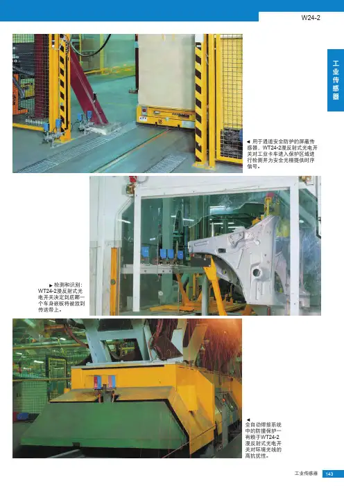
WS/WE45 对射式光电 开关监测纸 卷中的纸张 是否断裂。
在轧钢厂中, 钢鳞、蒸汽和高 温都不会影响 WT45—此时它 正在检测钢板的 存在。
钢厂中极端的运行条件—WT45 漫反射式光电开关是许多应用的 理想选择,例如钢片在绕圈之前 的检测。
工业传感器 161
检测距离 400...2000 mm
400/s
预故障信号输出
报警输出
最大输出电流
100 mA,集电极开路
接收光线不足 (冗余量<50%)
闪烁频率约为5/s,切换到Vs
测试输入 »TE«
发射器关闭
PNP:测试输入接到0 V
连接方式
NPN:测试输入接到Vs 接线端子连接
VDE保护等级7) 电路保护8) 防护等级
A,B,C, IP 67
工作环境温度9) 存储环境温度9) 重量 前镜加热 偏光滤镜 外壳材料
连接方式
接线端子连接
VDE保护等级 电路保护5) 防护等级
A,C IP 67
工作环境温度 存储环境温度 重量 前镜加热 外壳材料
1) TA=+25℃时的平均使用寿命 为100.000小时。
2) 为感性和容性负载提供适当 的火花抑制
-25℃...+55℃6) -40℃...+70℃ 约800g
金属外壳
漫反射式光电开关
坚固的金属外壳 红外光源,长检测距离 可调校的背景遮蔽功能 前镜加热,可选
参见“附件”章节 安装支架 特殊附件
162 工业传感器
WT45 漫反射式光电开关,红外光源,带背景遮蔽功能—直流电源
尺寸图
53 30 5
60
2
3
1
4
34 40
可调校型号 WT 45-P 250 WT 45-P 260 WT 45-P 250 WT 45-P 260
可调
工
光源种类1)
红色可见LED灯
业
光点直径
在检测距离16m处约为230mm
传
工作电压Vs 残余纹波3)
电流消耗4)
10...60 V DC2)
<5Vss ≤ 50 mA
感 器
≤ 250 mA,前镜加热
开关输出
PNP、Q和Q
NPN、Q和Q
最大输出电流
200mA
响应时间5)
≤ 1.2 ms
最大开关频率6)
漫反射式光电开关
通用电压 坚固的金属外壳 红外光源,长检测距离 可调校的背景遮蔽功能 前镜加热,可选
参见“附件”章节 安装支架 特殊附件
164 工业传感器
WT45 漫反射式光电开关,红外光源,带背景遮蔽功能—UC电源
尺寸图
53 30 5
60
2
3
1
4
105 A
M6
A
1
83
5
6
21 105
34 40
11
-25℃...+55℃ -40℃...+70℃ 约800g
金属外壳
1) TA=+25℃时的平均使用寿命 为100.000小时。
2) 限定值
3) 不可以超出供电电压Vs 允许范围值
4) 空载 5) 带阻抗负载时的信号传输时间
检测距离和工作裕量
11
45
55
2 0,01
28 35
3 0,01
25 30
100
技术资料
WT45- P 250 P 260 N 250 N 260
检测距离
400...2000mm,可调
光源种类1) 光点直径
LED,红外光源 在检测距离2000m处约为35mm
工作电压Vs 残余纹波3)
电流消耗4)
10...60 V DC2) <5Vss ≤ 50 mA ≤ 250 mA,前镜加热
订货号
1 008 840 1 008 668 1 008 839 1 008 669
工作裕量
反射镜类型
1 OP60-∞ 2 4×PL80 3 PL80A 4 C110 5 PL50 6 PL30 7 钻石级
反射胶贴
工作距离
1...45m 0.01...28m 0.01...25m 0.1...15m 0.01...11m 0.01...9m 0.3...8m
4 0.1
15 18
5 0,01 11 14
6 0,01 9 11
7 0.3 8 10
10
0 (m) 10 20 30 40 50 60
6) 亮/ 暗比例1:1 7) A=Vs反极性保护
B=Q和Q输出短路保护 C=干扰脉冲抑制
3
8) 带冷却板时最高温度可达 140℃(详参见附件)
订货信息 型号 WL 45-P 250 WL 45-P 260 WL 45-N 250 WL 45-N 260
0.015-0.3 s
t0 无延时 t1 当物体进入检测区域时
延时开启
t2 当物体离开检测区域时 延时关闭
PG13.5; 接线端子
1 L+
2
M
3
4
Q
5
Q
6 TE
WL45
技术资料
WL45- P 250 P 260 N 250 N 260
检测距离,最大典型值/反射镜 0.01...55m/OP 60
灵敏度
W45概述: 坚固的金属外壳,用于苛刻
的 工业应用。 对射式光电开关长达300米的 超远检测距离。 用于专业应用的附件。 通用的工作电压。 可根据用户要求提供:检测
表 面非常热(>800℃)的物体 的专用设备
主要行业: 钢铁工业 工厂建设 起重机系统 运输技术
160 工业传感器
坚固的设计以及 超远的检测距离 使WT45漫反射式 光电开关在检测 卷纸机中纸张断 裂时优势尽显。
工业传感器 165
检测距离 0.01...55 m
镜反射式光电开关
坚固的金属外壳 红色光源 灵敏度可调 前镜加热,可选 预故障信号输出
参见“附件”章节 安装支架 反射镜 特殊附件
166 工业传感器
WL45 镜反射式光电开关,红色光源—直流电源
尺寸图
53 30 4
60
2
3
1
105 A
M6
A
3
83
4
5
21 105
44 25
11
33.4
28
25
98
可调校型号
WL 45-P 250 WL 45-P 260 WL 45-N 250 WL 45-N 260
0,5 - 12 s 0,015 - 0,3 s
t0
t0
8 t3 t4
t1 t2
7
t
6
123 456
9 10
连接方式
WL 45-P 250 WL 45-P 260 WL 45-N 250 WL 45-N 260
M6
A
3
83
4
5
21 105
44 25
11
33.4
28
25
98
可调校型号 WL 45-R 250 WL 45-R 260
0,5 - 12 s 0,015 - 0,3 s
t0
t0
8 t1 t2
t1 t2
7
t
6
123 456
9 10
连接方式 WL 45-R 250 WL 45-R 260
漫反射式光电开关, 带背景遮蔽功能 镜反射式光电开关
对射式光电开关
W45 光电开关
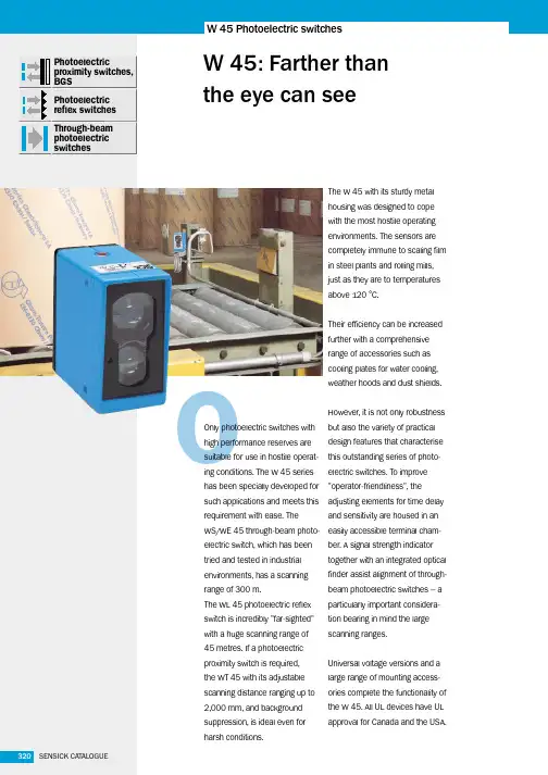
W45:比眼睛看得更远
另外一个重要特点是操作简 便,如易于连接的端子盒和定 时元件提供的额外功能等。
冷却板、天气防护罩和防尘罩 等众多附件确保光电开关性能 更好、应用范围更广。
在苛刻环境条件下,光电开关 在规格和性能方面都需要做到 更加稳定和可靠。W45系列光 电开关可以轻松满足这些需 求。其中最突出的产品就是对 射式光电开关,它的检测距离 长达300米,配备的信号强度指 示灯与集成的对位瞄准镜联合 使用,大大地方便了调校的过 程。 坚固的金属外壳可以承受钢铁 厂的恶劣环境,冷却板可以在 高达120℃的温度中正常工作。
光源种类1) 光点直径
LED,红外光源 在检测距离2000m处约为35mm
工作电压Vs 功耗