北京华德液压阀样本
华德比例阀样本[1]
![华德比例阀样本[1]](https://uimg.taocdn.com/5a17c2dc84254b35eefd3423.webp)
槽逐渐打开,从而控制液流流量,若断电时阀芯靠复位弹簧复位。
当电磁铁未通电时,阀芯(3)由复位弹簧(2)保持中位,如电磁铁A通电,电磁铁推杆直接推动阀芯(3)右移,位移量与电器...2X/...HD-4WRE(E)型阀是靠比例电磁铁操纵的直动型比例换向,用来控制液流的流量和流动方向。
该阀由阀体(1)、一个或两个弹簧(2)型:HD-4WRE(E)(5)、可选内置放大器(6)组成。
电磁铁的控制可通过外部放大器(HD-4WRE)或内置放大器阀芯(3)、一个或两个比例电磁铁—带直动式比例电磁铁的比例换向阀—底板安装—用来控制流量和流动方向—主阀芯弹簧对中—可选带内置放大器,HD-4WREE10型输入可选A1或F1—阀控制通过螺纹连接比例电磁铁实现,线圈可单独拆卸通径压力至流量至6、1031.5MPa180L/minHD-4WRE(E)-2X型电磁比例换向阀北京华德液压工业集团有限责任公司信号成正比,使阀芯(3)的节流—阀和比例放大器配套供应HD-4WRE6...-2X/G24Z4HD-4WREE10...-2X/G24Z4(HD-4WREE)实现。
说明广泛应用于机床、轻工、冶金、矿山、航天等各领域中。
此类阀与HD-4WRE型基本原理相同。
只是这类阀为仅有一个电磁铁"a"的二位比例换向阀。
HD-4WRE比例换向阀采用板式连接,弹簧对中;阀体采用铸造内流道通流能力强,重复精度好;底板安装尺寸与HD-4WRE···A-2X/···型二位四通比例阀a PPTAoB T不带内置放大器比例方向阀HD-4WRE···-2X/···型三位四通比例阀aAa o图形符号B b bHD-4WREE10...A-2X/G24Z4HD-4WRE6...A-2X/G24Z4A-2X/型(二位阀)通用性好;···HD-4WRE 电磁阀相同,二位四通比例阀HD-4WREE···A-2X/···型ab PTAaoB PT 带内置放大器比例方向阀三位四通比例阀HD-4WREE···-2X/···型aB Ao bbGGaGaG接线方式PE12PE型号说明插头连接形式A 2插座连接形式A B12与放大器连接121B说明:对于说明阀芯和,在中位时口至口,以及口及口约有相当于额定值的通流面积4WRA型(外控放大器)与放大器连接PE PE外置HD-VT-VSPA2-1/T1;HD-VT-VSPA2-2/T16-20至+702.8至500矿物油,磷酸质油≤20(为保证阀系统控制性好和寿命长推荐≤10)放大器的电气参数阀的保护型式符合标准DIN40050线圈温度(C°)线圈电阻(Ω)单个电磁铁最大电流(A)名义电压(V)电流消耗放大器电源电压通电率电气形式通径3最大脉冲电流AImax A上限值V 下限值V额定电压VDC在(20C°)时最大热值24<219.435直流电磁铁的电气参数介质温度(C°)工作压力MPa介质粘度(Kg)反向误差(%)重复精度(%)滞环(%)过滤精度液压部分技术参数31.5A、P、B口T口-20至+50≤0.1≤0.05≤0.0525、50、7521通径6可达150IP653100%224直流1031.52110mm /S 8、16、32最大允许流量(L/min)180802.8至3806.36.52.22.44WRE 4WREE 4WRE 4WREE4WRE4WREE vmax 电气部分(放大器与接线盒配套供应)额定流量Q 在ΔP=1MPa时(L/min)重量介质内置放大器HD-VT-4WREE6-2X;HD-VT-4WREE10-2X2.52(μm)HD-4WREE 型内置放大器CD±10V/4...20mA(Diff.)Reference(Diff.)Reference(Actual Value)0V+24V Actual Value Zero±10V/4...20mA(实际值)+24V 0V实际值的参考电位实际值输入±10V/4...20mA(信号输入)U UU IU IU U=≈=≈UU零位振荡器解调器实际值基准电压增益位移传感器七芯插座接口内置放大器阀差动放大器斜坡发生器2)加法器输出端输出端互锁低电压识别电源D EA B PE给定量基准电压24V GND 屏蔽保护电源电压+Ui 0 V -UiD E1)3)内置放大器的方框图/接线图说明:从控制放大器引出的电信号(例如:实际值)不允许用于开关设备的安全保护功能!(请参考欧洲标准“流体技术设备和元件的安全保护要求”—液压技术“EN 982!)1)接点PE 应与温度较低物体及阀体连接;2)斜坡时间可从外部在0到2.5s 调校;同样适用T 和T ;up down 3)零点外部可调.A B F E D C2)3)m 801U 型号4WREE6V321001U L△P SP i n %HD-4WREE 比例电磁阀特性曲线(ν=36×1050泄漏油流量特性曲线(阀芯处于中位)0泄漏油流量L /m i n12100工作压力bar150压力-输入信号特性曲线(V形机能)P=10MPa200250300/St=50°C)通径6和10-62204060100-80-100-20-40-60-5-3-135EENU in %L △P SP i n %21031520406080-80-100-20-40-60-5-3-135EENU in %500泄漏油流量L /m i n12100工作压力bar150200250300210315型号4WREE10V75通径6通径10HD-4WREE 比例电磁阀特性曲线(P=10MPa,ν=36×10通径6ΔP 2010流量L /m i nA 4m A 60A 32120阀的压差为1MPa时,额定流量为16L/min阀的压差为1MPa时,额定流量为8L/min=阀的压差(进口和出口控制台肩的总压降)503、ΔP =3MPa 恒定4、ΔP =5MPa 恒定5、ΔP =10MPa 恒定1、ΔP =1MPa 恒定2、ΔP =2MPa 恒定20304030给定值%/St=50°C)10060708090P B /A T /B T P 或51322-6010802010504030706010090给定值%V 形机能E 和W 形机能3509080302010010207080605040给定值%3040506070流量L /m i n30201040E 和W 形机能10090100V 形机能12/B T /AT或60PB P 458090010201020301050403040506070608070或/AT30流量L /m i n205040PB /B T 阀的压差为1MPa时,额定流量为32L/minP E 和W 形机能10090100V 形机能145807010090110最大容许流量ΔP A m 给定值%A 50125100PB 150A 300180HD-4WREE 比例电磁阀特性曲线(P=10MPa,ν=36×10通径10阀的压差为1MPa时,额定流量为50L/min阀的压差为1MPa时,额定流量为25L/min=阀的压差(进口和出口控制台肩的总压降)503、ΔP =3MPa 恒定4、ΔP =5MPa 恒定5、ΔP =10MPa 恒定1、ΔP =1MPa 恒定2、ΔP =2MPa 恒定2020103040流量L /m i n4030506070给定值%/St=50°C)10060708090PB /AT/B T P或513242-680010802010504030706010090V 形机能E 和W 形机能31259080302010010207080605040给定值%3040506070流量L /m i n755025100E 和W 形机能10090100V 形机能12/B T /AT或150PB P 458090010201020302550403040506070608070或/AT75流量L /m i n/B T 阀的压差为1MPa时,额定流量为50L/minP E 和W 形机能10090100V 形机能32145200175250225275最大容许流量阀芯行程%1000100007500500025105010804020时间ms010203030203040609070信号变化区间%相位°幅值b B-10-15-20-25-301频率Hz103020-3-5020050100-45-135-90-180-225-270信号±100%信号±25%信号±10%HD-4WREE型频率响应特性曲线(P=1MPa,ν=36×10/S,t=50°C)-62通径64/3阀门型机能符号“V”010000750050002520050257560401000204060103020-3-135-10-15-20-25-301-55020050100-45-90-180-315-225-270HD-4WREE型频率响应特性曲线(P=1MPa,ν=36×104/3阀门型机能符号“V”通径10信号变化区间%时间ms阀芯行程%/S,t=50°C)-62幅值b B相位°频率Hz信号±100%信号±25%信号±10%HD-4WREE 型流量(P=1MPa,ν=36×10阀门压差barA /St=50°C)m 502510102010050200400180100300最大容许流量流量L /m i n101102010050200200100/B T P 300或/ATPB 最大容许流量-6280081632阀门在最大开启下的负载曲线标准流量为8L/min、16L/min、32L/min 通径6机能符号“V”需要考虑最大容许流量为80L/min!HD-4WREE型频率响应特性曲线(P=1MPa,ν=36×10通径10/S,t=50°C)-62阀门在最大开启下的负载曲线标准流量为25L/min、50L/min、75L/min 机能符号“V”/B T P A 或/ATPB 阀门压差bar流量L /m i nQ =375L/minmax 需要考虑最大容许流量为180L/min!A Ba ba b型号HD-4WREE6 (2X)P ATBG341/01G342/01G502/010.01/100mm阀固定螺栓:4个M5X40DIN912-10.9M =8.9NmA 安装底板:G341/01(1/4")G342/01(3/8")G502/01(1/2")0.8当无底板安装阀时,要求配合部件表面精加工3比例电磁铁"b"说明:阀在出厂前已经排气6阀的排气孔5标牌4.2黑色插头"B"4.1灰色插头"A"2带有感应位移传感器的比例电磁铁"a"1阀体(油口P、A、B、T)8O形圈9.25X1.7811阀底面油孔尺寸10取下插头所需空间9带一个电磁铁的阀的端堵(两位阀:机能为EA或WA)7感应位移传感器插座;TA PB阀固定螺栓:4个M6X40DIN912-10.9G534/01(3/4")M =15.5NmG67/01(1/2")安装底板:G66/01(3/8")A 0.01/100mm0.8型号HD-4WREE10 (2X)3比例电磁铁"b"说明:阀在出厂前已经排气6阀的排气孔5标牌4.2黑色插头"B"4.1灰色插头"A"2带有感应位移传感器的比例电磁铁"a"1阀体(油口P、A、B、T)8O形圈12X211阀底面油孔尺寸10取下插头所需空间9带一个电磁铁的阀的端堵(两位阀:机能为EA或WA)7感应位移传感器插座;P A TAB TB当无底板安装阀时,要求配合部件表面精加工。
液压阀产品样本
5 . 1 × 4 1 M
55 124
29
5
YHCO 邵阳维克液压
单 向阀
单向阀
单 向阀 在液 压系 统中 ,使 油液 以一 定的 开启 压力 在某 个方 向自 由通 过 , 而反 向不 允许 通 过 。 单向阀分直通与直角两种形式。
技术规格
公称压力公称流量开启压力 重量
型
号
液压符号
MPa DIF- L10H ※ DIF- L20H ※ DIF- L32H ※ DF- L10H ※ DF- B10H ※ DF- L20H ※ DF- B20H ※ DF- L32H ※ DF- B32H ※ 31.5 31.5
M14 ×1. 5
2
YHCO 邵阳维克液压
φ 50
节流阀
单向节流阀
φD
出口
φd
泄油口
d1 F K
x a m H T P
G φD
进口
E S B
C
A
L
阀
型
号
A 71 81 106
B 97 112 140
C 51 49 66.5
L 15 17 20
E
F 27 31 46
H 20 14 18 204 272 282
目
LF 型 节 流 阀 KF 型 压 力 表 开 关 DF 型 单 向 阀 DFY 型 液 控 单 向 阀
电磁 换向阀 湿式 电磁换 向阀
录
1 5 6 9 13 19 23 24 30 34 36 39 41 43 46 49 52 55 57 62 67 76 80 86 96 118 121 128 130 132 136
kg 0.6
压 力 表 开 关
回油单向阀样本
华德液压
回油单向阀
技术样本
北京华德液压工业集团有限责任公司
HD-M-LSR...KD (1X)
北京华德液压工业
集团有限责任公司
1、概述
回油单向阀采用螺纹插装式结构,为工程机械提供高可靠的回油背压。
目前主要应用于市场吨以上挖掘机。
2、技术参数
机能符号及型号说明系列号
2.0=开启压力0.2MPa(限于规格50)5.0=开启压力0.5MPa(限于规格50)直通插装阀
=KD
螺纹插装式单向阀=M-LSR
规格50=50
KD
M-LSR
其它细节用文字说明
1X
HD -北京华德液压技术=HD 2.5=开启压力0.25MPa(限于规格40)4.5=开启压力0.45MPa(限于规格40)
规格40=40机能符号:
型号说明:
100200
300400500600700
0.10.20.30.40.50.60.70.8流量(L/min)
50
100
150200250300350400
00.10.20.30.40.50.60.050.150.250.350.450.55流量(L/min)
2
1
压力损失(M P a )
特性曲线(试验条件V=32mm 2
/S和温度t=50°C测得)
00
开启压力10.2MPa 2
0.5MPa
0.45MPa 0.25MPa
开启压力12
压力损失(M P a )
1
2
外形尺寸及连接尺寸
4
安装连接尺寸(参考):
0.4
0.4
销售服务热线。
北京华德A7VEP柱塞泵使用说明书
北京华德A7VEP柱塞泵使用说明书一、产品概述二、产品特点1.高效能:A7VEP柱塞泵的设计采用了先进的技术,能够提供高效的能量传递和工作效率。
2.低噪音:该柱塞泵的结构紧凑,工作时噪音低,有利于提升工作环境的舒适性。
3.高压力:A7VEP柱塞泵能够提供高压水平,满足各类液压系统的需求。
4.高精度:该柱塞泵具有很高的控制精度,能够精确地调节液压系统的压力和流量。
5.多种结构:提供多种组合、安装方式和轴向布局,满足不同液压系统的设计要求。
6.可靠性:经过严格的质量检测和耐久性测试,确保产品质量可靠,运行稳定。
三、安装前准备1.在安装过程中,确保工作场所干燥、清洁,并保证通风良好。
2.检查A7VEP柱塞泵的外观是否完好,是否有损坏,如有损坏应立即更换。
3.准备所需的工具和配件,确保安装顺利进行。
四、安装步骤1.将A7VEP柱塞泵放置在水平的工作台上,确保泵体平稳。
2.调整泵体的角度和位置,使得进出口法兰与管路连接方便。
3.使用合适的工具将法兰与进出口管路连接紧固。
4.安装泵体上的压力表和流量计,确保泵的运行状态可监测。
5.检查各管路连接是否牢固,无漏水情况。
6.连接电源并通电,启动柱塞泵,观察泵的运行状态是否正常。
五、使用方法1.在使用A7VEP柱塞泵之前,确保液压系统中的液压油符合规定的要求,并保持清洁。
2.确认液压系统内的压力设置合理并安全。
3.启动柱塞泵时应慢慢提高转速,以避免由于突然增大的流量导致过高的压力。
4.调节控制阀来控制流量和压力,在使用过程中避免超过柱塞泵的额定参数。
5.定期检查A7VEP柱塞泵的工作状态,包括噪音、温度等,如有异常情况应及时处理。
六、维护保养1.定期更换液压油,确保油质过滤并符合规定要求。
2.经常清理柱塞泵表面的污垢和积尘,保持清洁。
3.定期检查密封件的磨损情况,如发现磨损或老化应及时更换。
4.定期检查和紧固螺丝、法兰等连接件,确保连接处无松动。
5.注意防护柱塞泵工作时的高温和高压,避免触摸或靠近运转中的泵体。
SDV15和XDV20液体液压阀门说明书
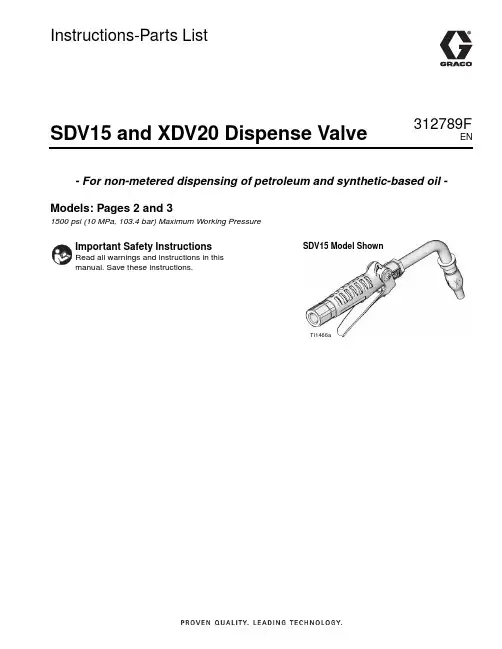
Instructions-Parts ListSDV15 and XDV20 Dispense Valve312789F- For non-metered dispensing of petroleum and synthetic-based oil - Models: Pages 2 and 31500 psi (10 MPa, 103.4 bar) Maximum Working PressureTI1466aSDV15 Model ShownENModelsModelsSDV15 Dispense Valve ModelsAll models include: 1/2 npt(f) swivel with locking-open triggerPart No.Extension Nozzles Fluid Type247712Rigid Automatic non-drip, quick close Oil247713Flexible Automatic non-drip, quick close Oil247714Gear Lube Automatic, non-drip, quick close Gear Lube247715Rigid Automatic, non-drip, quick close Anti-freeze247716Flexible Automatic, non-drip, quick close Anti-freeze247717NONE NONE AllAll models include: 1/2 - 14 BSPP swivel with locking-open triggerPart No.Extension Nozzles Fluid Type24H384Rigid Automatic non-drip, quick close Oil24H385Flexible Automatic non-drip, quick close Oil24H386Gear Lube Automatic, non-drip, quick close Gear Lube24H387Rigid Automatic, non-drip, quick close Anti-freeze24H388Flexible Automatic, non-drip, quick close Anti-freeze24H389NONE NONE AllAll models include: 1/2 - 14 BSPT swivel with locking-open triggerPart No.Extension Nozzles Fluid Type24H390Rigid Automatic non-drip, quick close Oil24H391Flexible Automatic non-drip, quick close Oil24H392Gear Lube Automatic, non-drip, quick close Gear Lube24H393Rigid Automatic, non-drip, quick close Anti-freeze24H394Flexible Automatic, non-drip, quick close Anti-freeze24H395NONE NONE All2312789FModelsXDV20 Non-metered Valve ModelsNPT Models - All models include locking-open and closed triggerPart No.Swivel Extension Nozzles Fluid Type 2477181/2” npt (f)Rigid High flow, non-drip, quick close Oil / Anti-freeze 2477211/2” npt (f)Flexible High flow, non-drip, quick-close Oil / Anti-freeze 2477223/4“ npt (f)Rigid High flow, non-drip, quck close Oil / Anti-freeze 2477233/4” npt (f)Flexible High flow, non-drip, quick close Oil / Anti-freeze 2477241/2” npt (f)NONE NONE Oil / Anti-freeze 2477253/4” npt (f)NONE NONE Oil / Anti-freezeBSPP Models - All models include locking-open and closed triggerPart No.Swivel Extension Nozzles Fluid Type 24H4071/2” - 14 BSPP Rigid High flow, non-drip, quick close Oil / Anti-freeze 24H4081/2” - 14 BSPP Flexible High flow, non-drip, quick-close Oil / Anti-freeze 24H4093/4“- 14 BSPP Rigid High flow, non-drip, quck close Oil / Anti-freeze 24H4103/4” - 14 BSPP Flexible High flow, non-drip, quick close Oil / Anti-freeze 24H4111/2” - 14 BSPP NONE NONE Oil / Anti-freeze 24H4123/4” - 14 BSPP NONE NONE Oil / Anti-freezeBSPT Models - All models include locking-open and closed triggerPart No.Swivel Extension Nozzles Fluid Type 24H4131/2” - 14 BSPT Rigid High flow, non-drip, quick close Oil / Anti-freeze 24H4141/2” - 14 BSPT Flexible High flow, non-drip, quick-close Oil / Anti-freeze 24H4153/4“ - 14 BSPT Rigid High flow, non-drip, quck close Oil / Anti-freeze 24H4163/4” - 14 BSPT Flexible High flow, non-drip, quick close Oil / Anti-freeze 24H4171/2”- 14 BSPT NONE NONE Oil / Anti-freeze 24H4183/4” - 14 BSPT NONE NONE Oil / Anti-freeze312789F3WarningsWarningsThe following warnings are for the setup, use, grounding, maintenance, and repair of this equipment. The exclama-tion point symbol alerts you to a general warning and the hazard symbol refers to procedure-specific risk. Refer back to these warnings. Additional, product-specific warnings may be found throughout the body of this manual where applicable.4312789FInstallation312789F 5InstallationGroundingThe equipment must be grounded. Grounding reduces the risk of static and electric shock by providing an escape wire for the electrical current due to static build up or in the event of a short circuit.Pump: follow manufacturer’s recommendations.Air and fluid hoses: use only grounded hoses. Air compressor: follow manufacturer’s recommenda-tions.Fluid supply container: follow local code.To maintain grounding continuity when flushing or reliev-ing pressure , always hold metal part of valve firmly to side of grounded metal pail, then trigger valve.Pressure Relief Procedure1.Turn off power supply to pump.2.Trigger valve into waste container to relieve pres-sure.3.Open any bleeder-type air valves and fluid drainvalves in the system.4.Leave drain valve open until you are ready to pres-surize the system.If you suspect the spray tip or hose is clogged or that pressure has not been fully relieved after following the steps above, VERY SLOWL Y loosen tip guard retaining nut or hose end coupling to relieve pressure gradually, then loosen completely. Clear hose or tip obstruction.Pre-Installation Procedure1.Relieve pressure as described in Pressure ReliefProcedure.2.Close fluid shut-off valve (A, F IG . 1).3.Ground hose, reel and console (See Grounding ).NOTICEDo not use PTFE tape on pipe joints; it may cause aloss of ground across the pipe joint.The equipment stays pressurized until pressure is manually relieved. To reduce the risk of serious injury from pressurized fluid, accidental spray from the dis-pense valve or splashing fluid, follow this Pressure Relief procedure whenever you:•Are instructed to relieve pressure•Check, clean or service any system component •Install or clean fluid nozzlesInstallation6312789FTypical InstallationF IG . 1 shows a typical installation. The installation is only a guide. The components shown are typical; however, it is not a complete system design. Contact your Graco distributor for assistance in designing a system to suit your particular needs.Dispense valves can also be installed on a console.Installation Procedure1.Relieve pressure , page 5.Steps 2 - 6 are the Flushing Procedure.2.Close fluid shut-off valve (A) at each dispense posi-tion.3.Make sure main fluid outlet valve at pump is closed,the air pressure to the pump motor is adjusted, and the air valve is open. Slowly open main fluid valve.4.Place hose end (with no dispense valve connected)into a container of waste oil. Secure hose in con-tainer so it will not come out during flushing. If you have multiple dispense positions, flush the dispense position farthest from pump first and work your way toward the pump.5.Slowly open fluid shut off valve (A) at dispense posi-tion. Flush out a sufficient amount of oil to ensure the entire system is clean. Close valve.6.Repeat Step 5 for all dispense positions.•Do not use this dispense valve on non-Graco con-soles. Such use could result in trigger becoming inadvertently pressed while valve is stowed.•To prevent line contamination, which can cause equipment damage or malfunction, flush the lines before your install the equipment in the system.F IGIf this is a new installation, or if the lines are contami-nated, flush the lines before you install dispensing valve.Key DescriptionA Fluid shutoff valveBHoseC Hose reel fluid inlet hoseD Hose reel EDispense valveA Thermal Relief Kit (not shown) is required.The Kit required will vary by pump selected. See Parts, page 16 for a list of available kits.Operation312789F 7Existing Installation1.Relieve pressure , page 5.2.Loosen and disconnect hose from old dispensevalve (the one you are replacing).Existing or New InstallationFor Steps 3 - 5 see F IG . 2.3.Thread extension (11) into outlet of the dispensevalve handle (1). Tighten securely.4.Apply thread sealant to male threads of hose fitting.Thread hose fitting into swivel (6). Tighten firmly.5.Thread nozzle (12) or nozzle adapter onto extensionand tighten firmly.6.Open all dispense position shut-off valves. Startpump to pressurize system.OperationFor part numbers referenced in these instructions, see Parts, page 10.Dispensing Procedure1.Open (or unlock) nozzle.2.Pull trigger (15) toward the valve handle (1) to openvalve and begin dispensing.3.Lock valve open by keeping trigger (15) squeezedand depressing trigger lock button (14). Then you can release trigger.4.To release trigger lock (14), pull trigger (15) towardvalve handle (1). 5.Release trigger (15) to stop dispensing.6.Close (lock) nozzle.•Do not overtighten extension.•Thread extension in at least three full turns. Position extension for proper alignment with valve handle (1) and tighten nut (11a).F IG. 2611a11121ti11466aTo reduce the risk of a serious bodily injury, including fluid injection, never exceed the maximum working pressure of the valve you are using or of the lowest rated component in your system.The XDV20 dispense valve trigger automatically locks whenever you release the trigger and must be unlocked each time you begin a new dispense.Troubleshooting8312789FTroubleshootingRelieve pressure before you check or repair dispense valve. Be sure all other valves and controls and the pump are operating properly.*Some fluid seepage is possible in applications where thermal expansion of fluid is possible.ProblemCauseSolutionSlow or no fluid flowScreen is clogged 1.Relieve pressure.2.Clean or replace strainer (4a)and washer 4b. Order Filter Kit 256164.3.If the problem remains, contactyour Graco distributor for repair or replacement.Pump pressure is low Shutoff valve is not full openOil leaks from swivel Swivel is looseT orque the swivel (6) to 7-10 ft-lb (9-13 N.m).If the problem remains, contact your Graco distributor for repair or replacement.O-ring is worn or damagedReplace swivel (6). Torque swivel to 7-10 ft-lb (9-13 N.m).If the problem remains, contact your Graco distributor for repair or replacement.Oil drips from nozzle*Nozzle is damaged or obstructed Inspect nozzle for damage or obstructions. Replace if damaged.Valve leaksO-rings or valve seat are worn or damagedReplace seals (9) and/or valve seat (2).Service312789F 9ServiceValve Handle Repair1.Relieve pressure , page 5.2.If you are replacing the seals (9), the cam (8) or thepush rod (3), remove the swivel (6) and remove the internal pieces. You must remove the cam in order to get the push rod out of the valve end.3.Remove screws (7) and washers (10) and removetrigger (15). 4.Push cam (8) out of valve handle (1). 5.Replace seals (9) and/or cam (8).6.Replace any worn or broken parts.7.Reassembly internal parts. Refer to F IG . 3 for cor-rect installation order and orientation of parts.8.Lubricate the cam (8) and slide it into the valve han-dle (1), making sure the notch is oriented as shown in F IG . 3, with the large end of the push rod (3) rest-ing in the notch of the cam.9.Replace the screws (7) and seals (9). Torquescrews to 15 -25 in-lb (1.7 to 2.8 N•m).10.Replace swivel (6). Torque to 7-10 ft-lb (31 to 44N•m).Filter ReplacementOrder Filter Kit 256164.1.Relieve pressure, page 5.2.Unscrew hose fitting from swivel (6).3.Remove swivel (6) from valve handle (1).4.Remove strainer (4a) and washer (4b) from inside ofswivel (6).5.Replace washer (4b) and strainer (4a). Refer to F IG .4 to ensure correct orientation of filter in swivel.6.Thread hose fitting into swivel (6) and tighten.Torque swivel to 7-10 ft-lb (31- 44 N•m).The large end of the push rod (3) fits into a notch in the cam (8) which is part of the trigger assembly. It is important you know this before you remove orinstall parts.The push rod (3) must be inserted through the out-let end of the valve handle before cam (8) is installed.F IG . 36173891015ti12073a710F IG . 4ti12074a14b 4a6Parts10312789FPartsSDV15 Dispense ValvesFN Part No.DescriptionQty 115R709HANDLE, valve, standard duty 12191313SEAT , valve 13277673ROD, push14256164KIT, filter, includes 4a and 4b 14a STRAINER 104b WASHER, plain106238399SWIVEL, straight, NPT 124H382SWIVEL, straight, BSPP 124H383SWIVEL, straight, BSPT 17110637SCREW, machine, pan head 28191315CAM19113574SEAL, quad ring 210191552WASHER, flat 211*KIT, nozzle and extension, page 12112*113113924SPRING, compression 11415R526LOCK, trigger 115191320TRIGGER 116192106GUIDE, spring 118113493SPRING, compression 120†172479T AG, warning 12215K672ADAPTER, o-ring, model 247714125†290180T AG, caution 1*These parts are not included on model 247717† Not shownFN Part No.DescriptionQty ti11467b64b4a18271013111215161413910781112111222T orque to 7-10 ft. lbs (9-13 N•m)112T orque to 15 - 25 in. lbs (1.7- 2.8 N•m)22Parts312789F 11PartsXDV20 Non-metered ValvesFN Part No.Description Qty 115M660HANDLE, valve, medium duty 1215U704SEAT , valve 13277673ROD, push 14256164KIT, filter, includes 4a and 4b 14a STRAINER 104b WASHER, plain 106247344SWIVEL, straight, 1/2 NPT models 247718, 247721, 247724124H097SWIVEL, straight, 1/2 BSPT, mod-els 24H413, 24H414, 24H417124H098SWIVEL, straight, 1/2 BSPP , mod-els 24H407, 24H408, 24H411247345SWIVEL, straight, 3/4 NPT models 247722, 247723, 24772524H099SWIVEL, straight, 3/4 BSPT, mod-els 24H415, 24H416, 24H418124H100SWIVEL, straight, 3/4 BSPP , mod-els 24H409, 24H410, 24H4127110637SCREW, machine, pan head 28191315CAM 19113574SEAL, quad ring 210191552WASHER, flat211*KIT, nozzle and extension, page 12112*113114680PIN, dowel 11415R016LATCH, pin 11515M886TRIGGER 11615R015LATCH, arm 11715R014LATCH, spring 11815R013LATCH, lever 120113493SPRING, compression 122†172479T AG, warning 12415U700PLUNGER, trigger, lift 12515U701SPRING, secondary 126†290180T AG, caution 1* These parts are not included on models 247724 or 247725† Not shownFNPart No.Description Qty ti12076a664b4a20217103121111710989171613181415T orque to 7-10 ft. lbs (9-13 N•m)1Torque to 15- 25 in. lbs (1.7- 2.8 N•m)222112524Parts12312789FSDV15 Nozzle Extension KitsPart No.DescriptionFluid Type*illustration note255852*Automatic, non-drip quick close nozzle with rigid extension.Oil255853*Automatic, non-drip quick close nozzle with flexible extensionOil255854Non-drip, quick close nozzle with rigid exten-sionGear Lube*Used for dispensing 5gpm (22.7 lpm) or less.continuedti11826ti11827ti11825ti11827ti11831ti11830ti12078aParts312789F 13255855*Non-drip, quick close nozzle with rigid exten-sionAnti-freeze255856*Non-drip, quick close nozzle with flexible extensionAnti-freeze255857Non-drip, quick close, high-flow nozzle with rigid extension Oil and Anti-freeze255858Non-drip, quick close, high flow nozzle with flexible extension Oil and Anti-freeze*Used for dispensing 5gpm (22.7 lpm) or less.Part No.Description Fluid Type*illustration noteti11826ti11828ti11825ti11828ti11826ti11829ti11825ti11829Parts14312789FSDV15 Nozzle KitsPart No.DescriptionQtyFluid Type255459*Automatic, non-drip, quick-close nozzle Oil• BODY , nozzle 1• O-RING, packing 1• SPRING, compression 1• O-RING, packing 1• STEM, nozzle, valve 1• SEAT, valve1255460*Automatic, non-drip, quick-close nozzle Anti-freeze• BODY , nozzle1• SPRING, compression 1• O-RING, packing 1• STEM, nozzle, valve,1• O-RING, packing 1• SEAT, valve1255461Automatic, non-drip, high-flow nozzle Oil and Anti-freezea • STEM, nozzle, qty 1b • BODY , nozzle, qty 1c • O-RING, packing, qty1d • O-RING, packing, qty 1e • O-RING, packing, qty 1255470Non-drip, quick-close nozzle Gear Lube • Housing 1• Body, nozzle 1• O-RING, packing 1• O-RING, packing,1• Plug, Hollow, hex1*Used for dispensing 5gpm (22.7 lpm) or less.Parts312789F 15XDV20 Nozzle Extension KitsXDV20 Nozzle KitsPart No.DescriptionFluid Type*illustration note255921Non-drip quick close,high flow nozzle with rigid extension. Oil and Anti-freeze255859Non-drip quick close, high flow nozzle with flexible extension.Oil and Anti-freezeti12680ati12679aPart No.DescriptionQtyFluid Type255793Non-drip, quick close, high flow nozzle Oil and Anti-freeze• O-RING, packing 1• O-RING, packing 1• BODY , nozzle, high flow 1• O-RING, packing 1• STEM, nozzle, heavy duty1Technical Data16312789FThermal Relief KitsTechnical DataPart No.DescriptionPSI (bar) Rating 112353Diaphragm pump for fuel dispense, valve only 50 psi (3.4 bar)235998Mini Fire-Ball ™ 225, 3:1 600 psi (41 bar)237601Fire-Ball 425, 3:1600 psi (41 bar)237893Fire-Ball 300, 5:1 and Fire-Ball 425, 6:1 900 psi (62 bar)248296Fire-Ball 300, 5:1 and Fire-Ball 425, 6:1 (same as 237893 minus bung adapter and swivel. Includes 6-foot hose)900 psi (62 bar)238899Diaphragm pump 150 psi (10.4 bar)240429Fire-Ball 425, 10:11600 psi (110 bar)248324Fire-Ball 425, 10:1 (same as 240429 minus bung adapter and swivel. Includes 6-foot hose)1600 psi (110 bar)Maximum Flow RangeSDV1515 gpm (56.8 lpm)XDV2020 gpm (75 lpm)Maximum Working Pressure SDV15/XDV201500 psi (102 bar)SDV15/XDV20 Weight 0.4 lbs (0.18 kg)Inlet See pages 2 and 3 for models and configuration information OutletSDV153/4 - 16 straight thread o-ring boss XDV207/8 - 14 straight thread o-ring Operating temperature range -40°F to 180°F (-40°C to 82°C)Wetted partsAluminum, Stainless Steel, CS, Acetal, Nitrile Rubber, TPE Fluid compatibilityAntifreeze, gear lube, oilNotes Notes312789F17All written and visual data contained in this document reflects the latest product information available at the time of publication.Graco reserves the right to make changes at any time without notice.Original instructions. This manual contains English. MM 312789For patents see: /patentsGraco Headquarters: MinneapolisInternational Offices: Belgium, China, Japan, Korea GRACO INC. P.O. BOX 1441 MINNEAPOLIS, MN 55440-1441Copyright 2008, Graco Inc. is registered to I.S. EN ISO 90015/2008, Revised May 2016Graco 7-Year Meter and Valve WarrantyGraco warrants all equipment referenced in this document which is manufactured by Graco and bearing its name to be free from defects in material and workmanship on the date of sale to the original purchaser for use. With the exception of any special, extended, or limited warranty published by Graco, Graco will, for a period from the date of sale as defined in the table below, repair or replace equipment covered by this warranty and determined by Graco to be defective. This warranty applies only when the equipment is installed, operated and maintained in accordance with Graco’s written recommendations.This warranty does not cover, and Graco shall not be liable for general wear and tear, or any malfunction, damage or wear caused by faulty installation, misapplication, abrasion, corrosion, inadequate or improper maintenance, negligence, accident, tampering, or substitution ofnon-Graco component parts. Nor shall Graco be liable for malfunction, damage or wear caused by the incompatibility of Graco equipment with structures, accessories, equipment or materials not supplied by Graco, or the improper design, manufacture, installation, operation or maintenance of structures, accessories, equipment or materials not supplied by Graco.This warranty is conditioned upon the prepaid return of the equipment claimed to be defective to an authorized Graco distributor for verification of the claimed defect. If the claimed defect is verified, Graco will repair or replace free of charge any defective parts. The equipment will be returned to the original purchaser transportation prepaid. If inspection of the equipment does not disclose any defect in material or workmanship, repairs will be made at a reasonable charge, which charges may include the costs of parts, labor, and transportation.THIS WARRANTY IS EXCLUSIVE, AND IS IN LIEU OF ANY OTHER WARRANTIES, EXPRESS OR IMPLIED, INCLUDING BUT NOT LIMITED TO WARRANTY OF MERCHANTABILITY OR WARRANTY OF FITNESS FOR A PARTICULAR PURPOSE .Graco’s sole obligation and buyer’s sole remedy for any breach of warranty shall be as set forth above. The buyer agrees that no other remedy (including, but not limited to, incidental or consequential damages for lost profits, lost sales, injury to person or property, or any other incidental or consequential loss) shall be available. Any action for breach of warranty must be brought within one (1) year past the warranty period, or two (2) years for all other parts.GRACO MAKES NO WARRANTY, AND DISCLAIMS ALL IMPLIED WARRANTIES OF MERCHANTABILITY AND FITNESS FOR A PARTICULAR PURPOSE, IN CONNECTION WITH ACCESSORIES, EQUIPMENT, MATERIALS OR COMPONENTS SOLD BUT NOTMANUFACTURED BY GRACO . These items sold, but not manufactured by Graco (such as electric motors, switches, hose, etc.), are subject to the warranty, if any, of their manufacturer. Graco will provide purchaser with reasonable assistance in making any claim for breach of these warranties.In no event will Graco be liable for indirect, incidental, special or consequential damages resulting from Graco supplying equipment hereunder, or the furnishing, performance, or use of any products or other goods sold hereto, whether due to a breach of contract, breach of warranty, the negligence of Graco, or otherwise.Graco InformationTO PLACE AN ORDER, contact your Graco distributor or call to identify the nearest distributor.Phone: 612-623-6928 or Toll Free: 1-800-533-9655, Fax: 612-378-3590Graco 7-Year Meter and Valve Extended WarrantyComponentsWarranty PeriodStructural Components 7 years Electronics3 years Wear Parts - including but not limited to o-rings, seals and valves1 year。
华德液压新系列的比例阀和工业阀系列产品介绍

(1)4WRZ(E)10 25、50、85
25、50、85
(2)4WRZ(E)16 100、150
100、150
(3)4WRZ(E)25 220、325
270、325
(4)4WRZ(E)32 3、滞环(%)Βιβλιοθήκη 360 、520 <6
360、520 ≤6
4、重复精度(%)
<3
≤2
5、死区(%)
< 35
≤25
20通径 300L/min 30通径 500L/min
创新 协作 夯实生命线 突破 发展 打造十百千
Z2S6型叠加式液控单向阀
创新 协作 夯实生命线 突破 发展 打造十百千
创新 协作 夯实生命线 突破 发展 打造十百千
创新 协作 夯实生命线 突破 发展 打造十百千
Z2S6型叠加式液控单向阀 一、基本功能
创新 协作 夯实生命线 突破 发展 打造十百千
注1:对E1、W1、W8机能 P→A :qV B→T : qV /2 P→B : qV /2 A→T : Qv 对E2、W2机能 P→A :qV/2 B→T : qV P→B : qV A→T : Qv/2 对E3、W3、W9机能 P→A :qV/2 B→T : 不通 P→B : qV A→T : 不通
对E2、W2机能 P→A :qV/2 B→T : qV P→B : qV A→T : Qv/2
对E3、W3机能 P→A :qV/2 B→T : 不通 P→B : qV A→T : 不通
创新 协作 夯实生命线 突破 发展 打造十百千
4WRZ先导式比例换向阀
4WRZ型阀是由比例电磁铁控制的先导式比例换向阀,将电气信号 转化为液体压力信号,用于控制油压系统的流量和流动方向。该阀由先 导阀(3)、主阀芯(8)、主阀(7)、复位弹簧(9)等组成。
液压控制阀图片及说明
泰安科创矿山设备有限公司液压阀教程普通单向阀:(a)结构图(b)职能符号图1—阀体2—阀芯3—弹簧工作原理:普通单向阀的作用,是使油液只能沿一个方向流动,不许它反向倒流。
(a)所示是一种管式普通单向阀的结构。
压力油从阀体左端的通口P1流入时,克服弹簧3作用在阀芯2上的力,使阀芯向右移动,打开阀口,并通过阀芯2上的径向孔a、轴向孔b从阀体右端的通口流出。
但是压力油从阀体右端的通口P2流入时,它和弹簧力一起使阀芯锥面压紧在阀座上,使阀口关闭,油液无法通过。
图(b)所示是单向阀的职能符号图。
液控单向阀:(a)结构图 (b)1—活塞2—顶杆3—阀芯工作原理:当控制口K处无压力油通入时,它的工作机制和普通单向阀一样;压力油只能从通口P1流向通口P2,不能反向倒流。
当控制口K有控制压力油时,因控制活塞1右侧a腔通泄油口,活塞1右移,推动顶杆2顶开阀芯3,使通口P1和P2接通,油液就可在两个方向自由通流。
二、换向阀工作原理:该阀由阀体1、阀芯2和使阀芯转动的操作手柄3组成,在图示位置,通口P和A相通、B和T相通;当操作手柄转换到“止”位置时,通口P、A、B和T均不相通,当操作手柄转换到另一位置时,则通口P和B相通,A和T相通。
(b)所示是它的职能符号。
手动换向阀:(a)职能符号图(b)1—手柄2—阀芯3—弹簧〖JZ〗〗工作原理:图(b)为自动复位式手动换向阀,放开手柄1、阀芯2在弹簧3的作用下自动回复中位,该阀适用于动作频繁、工作持续时间短的场合,操作比较完全,常用于工程机械的液压传动系统中。
如果将该阀阀芯右端弹簧3的部位改为可自动定位的结构形式,即成为可在三个位置定位的手动换向阀。
图(a)为职能符号图。
机动换向阀:1弹簧2阀芯3压盖4凸轮压住滚轮工作原理:机动换向阀又称行程阀,它主要用来控制机械运动部件的行程,它是借助于安装在工作台上的挡铁或凸轮来迫使阀芯移动,从而控制油液的流动方向,机动换向阀通常是二位的,有二通、三通、四通和五通几种,其中二位二通机动阀又分常闭和常开两种。
方向类液压阀基本原理及应用
结构与工作原理:
SV和SL型阀是锥阀结构的液控单向阀,它可以由液压 启而允许油液在闭锁方向自由流通。
此类阀用于有液压回路部分的隔离,以避免管路破裂 时负载失压,或避免执行器在液压闭锁时因滑阀泄漏引 起的爬行或漂移。
该阀的组成主要包括阀体(1)、阀芯(2)、压缩弹 簧(3)和控制活塞(4)
2020/8/3
2020/8/3
2020/8/3
2020/8/3
此类阀的结构、功能及易出现的故障和4WE6相似,其 突出特点是节能,此类阀的电磁铁较普通电磁阀电磁铁短, 只有12V和24V两种适用电压,功率较普通电磁阀小,适用 于机床等中低压系统中。
2020/8/3
直推式电磁球阀
2020/8/3
HD-M-SED6…10/
2020/8/3
三、SV/SL型液控单向阀基本参数 1、最高工作压力:31.5MPa 2、控制压力:0.5~31.5MPa 3、工作介质:矿物质液压油;磷酸酯液压油 4、油温范围:-30~+80℃ 5、黏度范围:2.8~500mm2/s 2、最大流量:10通径 120L/min
20通径 300L/min 30通径 500L/min
2020/8/3
三、4WEH型电液换向阀基本参数
1、油口A、B、P最高工作压力:
H—4WEH:至35MPa; 4WEH:至28MPa
2、最大流量:
10通径 160L/min
16通径 300L/min
25通径 650L/min
32通径 1100L/min
3、最高控制压力:至25MPa
4、介质:矿物质压油;磷酸酯油
此阀由阀体(1)滚轮/推杆控制阀芯(3)和复位弹簧 (4)组成。当没有外力操纵时,控制阀芯(3)被复位弹 簧(4)保持在起始位置(切换位置b)。当外力操纵滚轮 /推杆的操纵力减小时,控制阀芯(3)被复位弹簧推回起 始位置。
MASCOT产品选型样本
201 支架 202 气缸 210 调节螺钉 211 执行机构推杆 213 行程刻度牌 225 活塞 227 弹簧扣 228 执行机构推杆垫片 229 弹簧 248 调节螺钉垫片 249 阀杆夹 253 支架衬套 256 固定环 271 活塞O形环 272 活塞推杆O形环 274 支架O形环 275 执行机构推杆O形环 348 执行机构推杆锁紧螺母
锻造
锻造车间的能力包括落锤锻造和自由锻造直径最大至1000mm的各种标准材料 和特殊材料,制造成阀盖、法兰、阀塞和阀座环。
配合
诸如大型加工中心和数控机床(CNC)等扩展 设备能够生产各种不同尺寸的阀组件。
涂装
可以满足各种不同的涂装要求,比如标准涂装、用于海上服务的厚涂层涂装,以及用 于高温场合的涂装要求。
MASCOT Industrial 15A Randor Street Campbellfield, Victoria 3061 Australia
Tel: +61 3 9357 6555 | Fax: +61 3 9357 6566 Email: sales@ | Web: 本手册仅供信息参考,我们会努力确保资料的准确性和所提供技术规格的精确度, 但手册内容不作为对 于产品本身的解释或担保。MASCOT Industrial保留对产品设计的更改或改进的权力,本手册中产品信息 和技术规格如有变更,恕不另行通知。MASCOT Industrial对产品的选型,使用和维护不予负责。产品的
高端技术 紧密关断
澳大利亚的制造能力
高可靠性 值得信赖
Page 2
源自澳大利亚的制造能力
MASCOT公司所具有的源自澳大利亚的制造能力包括针对困难工况,应用多种 材料和特殊设计,制造压力等级为ASME CL150至CL4500,尺寸范围由0.5” 至36”的球阀以及2.0”至48”的旋转阀(蝶阀、V形球阀、偏心旋塞阀)。 澳大利亚企业利用供应商合作关系来完成铸件的生产和阀组件的加工 这使加工车间的工作量更具弹性并且大大减少了生产交付周期。 与合作伙伴迄今二十年的合作使MASCOT公司在高品质和及时交付表现上取得 了有证明的良好记录。
北京华德液压2011-系统样本
企业近3年的主要业绩1、板带类序号 项 目 名 称 最大流量L/min 最高使用压力MPa 用 户 1 邯钢型钢轧机及收集区域液压系统 180L/min*5 30375L/min*3 13 邯郸钢铁集团有限公司 2首钢冷轧罩式退火工程精整区重卷包装机组液压系统 180L/min*6 12 中冶南方工程技术有限公司 3无锡西城冷轧液压系统 180L/min*3 28 一重大连国际科贸公司 4宁夏锦宁1850铝板带液压系统 250L/min*6 29 二重集团(德阳)重型装备有限公司 5六辊铜带精轧液压系统 260L/min*2 13 米诺轧制技术公司 6 重庆万达汽车板液压系统 260L/min 13105 L/min 30 北京钢研新冶工程公司 7 冠州冷轧、酸洗机组液压系统 260L/min105L/min 25/15 北京京诚之星科技开发公司 8 山东科瑞1450冷轧液压系统 130L/min 302*260L/min 10 北京京诚之星科技开发公司 9福建鼎信850热轧液压系统 4*260L/min 25 二重集团(德阳)重型装备公司 10 首钢1580热轧宽带液压系统 6*260L/min 30 首钢京唐钢铁联合公司2、高炉类序号 项 目 名 称 最大流量L/min 最高使用压力MPa 用 户 1山东寿光1250 M ³高炉液压系统 4*140L/min 25 山东寿光巨能公司 2 山东富伦1650m ³高炉液压系统 2*180L/min 253*130L/min 20 山东富伦钢铁有限公司 3 安钢5200 M ³高炉槽下、热风炉、 2*135L/min 31.5 出铁厂、炉顶液压系统 2*150L/min20 安阳钢铁股份有限公司 4 承德建龙1350 M ³高炉液压系统 2*130L/min25 承德建龙特钢有限公司 5沙钢5000 M ³及2500 M ³高炉液压系统 张家港宏昌钢板有限公司4、连铸类序号 项 目 名 称 最大流量L/min 最高使用压力MPa 用 户 1新冶钢六流方圆坯连铸机液压系统 中信泰富工程公司 2河北敬业1100连铸机液压系统 3*190L/min 20 大连加氢反应器公司 3承德建龙连铸机液压系统 2*150L/min 20 承德建龙钢铁公司 4福建三明连铸机液压系统 3*185L/min 21 福建三明钢铁公司 5邯钢异型坯连铸液压系统 2*220L/min 18 邯郸钢铁集团有限责任公司 6鞍钢小方坯连铸机液压系统 3*180L/min 20 鞍钢 7 首秦4300mm二期3#连铸机液压系统 2*270L/min 25 首秦金属材料公司3、炼钢类序号 项 目 名 称 最大流量L/min 最高使用压力MPa 用 户 1新冶钢120TRH炉液压系统 2*310L/mi 21 湖北新冶钢有限公司 2 迁钢RH炉液压系统 2*310L/mi 21 首钢新钢有限公司5、加热炉类序号 项 目 名 称 最大流量L/min 最高使用压力MPa 用 户1 河北九江加热炉液压系统 3*250L/min 19 重庆赛迪工业炉有限公司2 西南不锈加热炉液压系统 3*180L/min 17 重庆赛迪工业炉公司3 首钢线材加热炉液压系统 5*266L/min 17.5 首钢设计院4 首钢长治钢铁100万吨棒材加热炉液压系统 4*266L/min 19 首钢设计院5 京唐热轧加热炉液压系统 5*375L/min 20 首钢京唐联合有限责任公司6 大连步进梁式加热炉液压系统 3*180L/min 16 辽宁向导科技公司7 承钢加热炉液压系统 4*260L/min 20 中冶赛迪工程公司7、管道类序号 项 目 名 称 最大流量L/min 最高使用压力MPa 用 户1 江苏天淮钢管生产线液压系统 北京京城之星科技公司2 天津ERW660直缝焊管精整线液压系统 5*210/min 10 新冶高科技集团有限公司3 番禺扩径机液压系统 5*500/min 25 番禺珠江钢管(珠海)有限公司4 江阴140钢管预精整线液压站 2*250L/min 14 北京京诚之星科技开发公司5 迪拜钢管生产线液压系统 2*173L/min 14 北京京城之星科技公司8、非冶金1)路障序号 项 目 名 称 最大流量L/min 最高使用压力MPa1 路障液压系统 1.2L/min 162 路障液压系统 26.5L/min 232)市政环保序号 项 目 名 称 最大流量L/min 最高使用压力MPa1 垃圾站液压系统70L/min 8 27L/min 182 501LR垂直式垃圾压缩站48L/min 8 30L/min 186、棒线材类序号 项 目 名 称 最大流量L/min 最高使用压力MPa 用 户1 新疆八钢线棒液压系统 2*200L/min 13 冶金设备院2 邯钢线棒液压系统5*260L/min 16180L/min 20邯钢集团公司3 南昌优特钢生产线液压系统 3*190L/min 13 北京中冶设备研究设计总院4 瀚川鑫冶精整线液压系统 190L/min 14 北京瀚川鑫冶工程技术有限公司3)其它序号 项 目 名 称 最大流量L/min 最高使用压力MPa1 制砖机液压系统 360L/min 182 底盘翻转机液压站 10L/min 143 热模锻压力机液压系统 162 L/min 144 试验台液压系统 60L/min 205 农机液压站 400L/min 166 厨房设备配套液压 4.5L/min 87 硫化机液压系统 210L/min 10。