交流伺服系统中的死区效应分析与补偿
直驱式永磁同步电机伺服系统死区补偿方法

v e c t o r a n g l e a n d t h e D C v o l t a g e we r e mo n i t o r e d d u r i n g e a c h o n — o f s wi t c h p e i r o d,w i t h t h e t o o l o f mo v i n g a v e r a g e f i l t e r .T h e s i mu l a t i o n mo d e l a n d e x p e r i me n t a l p l a t f o r m or f d i r e c t — d i r v e P MS M s e r v o s y s t e m w e r e b u i l t .S i mu l a t i o n a n d e x p e r i me n t a l r e s u l t s s h o w e d t h a t t h i s me t h o d r e d u c e d t h e h a mo r n i c c u r r e n t o f s t a t o r , r e s t r a i n s t o r q u e r i p p l e s a n d s p e e d r i p p l e s .T h e me t h o d i mp r o v e d t h e s y s t e m’ S p e r f o ma r n c e .
2011 基于模糊控制零电流钳位逆变器死区补偿_刘栋良
逆变器和永磁同步电动机的结构如图 1 所示。 为了防止直流母线电压短路,必须在同一桥臂的功
率器件导通之前加入一定的触发死区。如图所示, 在关断 S1,开通 S2 之间增加一段时间(死区时间), 在死区时间内,当 a 相电流较大且 ia>0 时,逆变 器桥臂 a 相中的 S1 关断,同时 S2 没有开通,则电 流只能通过 VD2 二极管来续流,a 相电压在死区时 间内钳位于−Vdc/2;相反,在死区时间内,当 a 相电 流较大且 ia<0 时 S2 关断时,同时 S1 没有开通,则 电流只能通过 VD1 二极管续流,a 相电压在整个死 区时间内钳位于 Vdc/2,整个过程如图 2 所示。在图 2 中,由上到下五组曲线分别表示:实际参考电压, 同一桥臂的上、下两个功率器件的触发信号,逆变 器实际输出电压,输出电压和实际参考电压的误差。 由图 2 可以得出如下的结论:
(b)由正过零
图 4 电流过零分析
Fig.4 Current cross zero analysis
di 和 i 的模糊语言变量为{NB,NS,Z,PS, PB}。
dout 的模糊语言变量为{N,Z,P}。
模糊规则如下: 规则 1:IF i 为 NS AND di 为 NS 则 dout 为 N; 规则 2:IF i 为 NS AND di 为 PB 则 dout 为 N; 规则 3:IF i 为 PS AND di 为 NB 则 dout 为 P; 规则 4:IF i 为 PS AND di 为 PS 则 dout 为 P; 规则 5:IF i 为 NB 则 dout 为 N; 规则 6:IF i 为 PB 则 dout 为 P; 规则 7:IF i 为 Z AND di 为 NB 则 dout 为 P; 规则 8:IF i 为 Z AND di 为 PB 则 dout 为 N; 规则 9:IF i 为 Z AND di 为 Z 则 dout 为 Z。 根据以上的模糊控制算法,在零电流钳位时可 以得到正确的电流方向。 3.2 电压补偿计算[13] 当 ia 为正方向时,逆变器死区所导致的开通时 间误差和电压误差为
基于电角度相位补偿的死区在线补偿算法设计

基于电角度相位补偿的死区在线补偿算法设计
王珂;李扬;谢成杰
【期刊名称】《电力电子技术》
【年(卷),期】2024(58)4
【摘要】伺服系统在工业自动化领域得到了广泛应用。
为解决伺服系统中由死区效应引起的相电流畸变、转矩脉动及对伺服系统响应性能的影响,提出了一种基于电角度相位补偿的死区补偿方法。
该方法补偿编码器相位延时导致的电角度相位差,通过模型预测速度控制,对多个电流环周期的电角度进行预测,并针对Sigma-Delta ADC采集中的线性相位延时进行补偿,以此判断真实电流极性。
实验结果验证了所提死区补偿方法的有效性。
【总页数】5页(P17-21)
【作者】王珂;李扬;谢成杰
【作者单位】广东工业大学
【正文语种】中文
【中图分类】TN820.3
【相关文献】
1.基于死区补偿的电液伺服PDF控制器设计
2.一种新颖的基于死区时间在线调整的SVPWM补偿算法
3.基于最小开关损耗的在线延时死区补偿算法
4.基于干扰观测器的逆变器在线死区补偿
5.基于死区补偿的电液位置伺服系统自抗扰控制
因版权原因,仅展示原文概要,查看原文内容请购买。
外文翻译--关于交流伺服驱动器的死区效应的分析与补偿
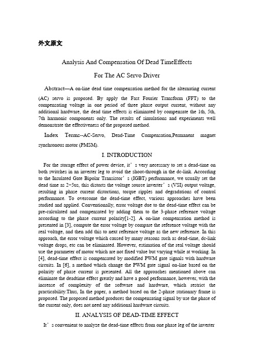
外文原文Analysis And Compensation Of Dead TimeEffectsFor The AC Servo DriverAbstract—A on-line dead time compensation method for the alternating current(AC) servo is proposed. By apply the Fast Fourier Transform (FFT) to the compensating voltage in one period of three phase output current, without any additional hardware, the dead time effects is eliminated by compensate the 1th, 5th, 7th harmonic components only. The results of simulations and experiments well demonstrate the effectiveness of the proposed method.Index Terms--AC-Servo, Dead-Time Compensation,Permanent magnetsynchronous motor (PMSM).I. INTRODUCTIONFor the storage effect of power device, it’s very necessary to set a dead-time on both switches in an inverter leg to avoid the shoot-through in the dc-link. According to the Insulated Gate Bipolar Transistor’s (IGBT) performance, we usually set the dead time as 2~5us, this distorts the voltage source inverter’s (VSI) output voltage, resulting in phase current distortions, torque ripples and degradations of control performance. To overcome the dead-time effect, various approaches have been studied and applied. Conventionally, error voltage due to the dead-time effect can be pre-calculated and compensated by adding them to the 3-phase reference voltage according to the phase current polarity[1-2]. A on-line compensation method is presented in [3], compute the error voltage by compare the reference voltage with the real voltage, and then add this to next reference voltage as the new reference. In this approach, the error voltage which caused by many reasons such as dead-time, dc-link voltage drops, etc can be eliminated. However, estimation of the real voltage should use the parameter of motor which are not fixed value but varying while at working. In [4], dead-time effect is compensated by modified PWM gate signals with hardware circuits. In [6], a method which change the PWM gate signal on-line based on the polarity of phase current is presented. All the approaches mentioned above can eliminate the deadtime effect greatly and have a good performance, however, with the increase of complexity of the software and hardware, which restrict the practicability.Thus, In the paper, a method based on the 2-phase stationary frame is proposed. The proposed method produces the compensating signal by use the phase of the current only, does not need any additional hardware circuits.II. ANALYSIS OF DEAD-TIME EFFECTIt’s convenient to analyze the dead-time effects from one phase leg of the inverterand extend the result to other phase legs. Figure.1 shows the basic configuration of onephase leg of the inverter. Define the direction of phase current flow to load is positive.Figure.1. one phase leg of the inverterA.when phase current ia is positive:When upper switch A+ turn on, lower switch A- turn off: During the dead-time and before the A+ turn on completely, the voltage of point a is clamped to –Udc/2for the D- turned on, the phase current flows through A+until A+ turned on, thus, the error time caused by deadtime effect is Td+ton, where ton is the IGBT’s turn on delay time.When upper switch A+ turn off, lower switch A- turn on: phase current flows through A+ before A+ turned off, and flows through D- when turned off. Thus, the error time caused by dead-time effect is toff, where toff is the IGBT’s turn off delay time.B. when phase current ia is negtive:When upper switch(A+)-turn on, lower switch (A-) turn off: phase current flows through A- before A- turned off, and flows through D+ when turned off. Thus, the error time caused by dead-time effect is toff. When upper switch (A+) turn off, lower switch (A-) turn on: During the dead-time and before A- turn on completely, the voltage of point a is clamped to +Udc/2 for D+ turned on. Thus, the error time caused by deadtime effect is Td+ton.Figure.2(a) shows the ideal gate signal patterns, Figure.2(b) shows the practical signal patterns considering the dead-time, Figure.2(c) shows the actual output voltage considering the dead-time and switching time for ia>0 and ia<0.Figure.2. practical switching pattern considering the dead-time and turnon/off time of switching devices. (a) ideal gate signal patterns. (b)practical signal patterns considering the dead-time. (c) actual outputvoltage considering the dead-time and switching timeThe average error voltage can be calculated from Figure.2 as in (1):d a d a U if i 0U U if i 0δ-∆〉⎧=⎨+∆〈⎩ , , (1) Where d dc s T UU T δ∆=,d on off T T t t δ=+-.According to (1) , the most obvious impact of deadtime effect is lower the output voltage, resulting in harmonics in phase current, torque ripple and speed fluctuation, especially in low speed.II. COMPENSATION OF DEAD-TIME EFFECTThe main principle of the compensation is produce a same amplitude and opposite sign voltage with the error voltage to decrease or eliminate the effect of dead-time. From (1), amplitude of the error voltage which depend on dead-time, switch period, switching time and dc-link mvoltage is fixed for off-line compensation. The key of compensation is to judge polarity of the phase current. It ’s difficult to judge the polarity of phase current accurately in the real control system, however, and the ambiguity at the zero point of phase current will deteriorate the compensation effect. Thus, in this paper, a compensation method which depend on the phase of current only in the 2-phase stationary (α /β ) frame is proposed. The error voltage depend on the polarity of phase current, so three phase current will have six different combinations of the error voltage vector. Table.I shows ,the error voltage and it ’s vector at different polarity of three phase current, where 1,22323d d K U K U =∆=∆.TABLE IERROR VOLTAGE VECTOR ACCORDING TO THE POLARITY OF THREEPHASE CURRENTFigure.3 shows the compensation voltage vector. Thecompensation voltage vector move discontinuously, andits trajectory is hexagon.Figure. 3. compensation voltage vectorThe current vector in 2-phase rotary ( d / q ) frame as shown in Figure.4. The phase of current vector can be obtained from Figure.4 as: e w dt ϕθ=+⎰Figure. 4. Phase of current vectorThe rotor flux orientated control technology be used to control PMSM in the servo system, and realize decoupling by control 0d I =, therefore, 90o θ= .Current vector with respect to error voltage vector asshown in Table.II.TABLE.II CURRENT VECTOR WITH RESPECT TO ERROR VOLTAGE VECTORBy considering the periodicity and parity of the compensation voltage vector in the α /β frame, the Fourier transform can be summarized as in (2):alfa bet 11a cos()U sin()n n n n U a n b n ϕϕ∞=∞=⎧∆=⎪⎪⎨⎪∆=⎪⎩∑∑ (2) Where n a can be calculated as in (3):0160566562222cos()24(()cos()32()cos()32()cos()34()cos()38115(sin sin sin )326226(1,2,3...)nn n d d d d d a a n d U n d U n d U n d U n d U n n n n ππππππππϕϕπϕϕπϕϕϕϕϕϕππππ∞==∆+∆+-∆+-∆∆=++=∑⎰⎰⎰⎰⎰ (3) In a similar way, n b is represented as in (4):a 0lfa sin()285(cos cos )366(1,2,3...)n d b U n d U n n n ππϕϕπππ=∆∆=-=⎰ (4) Using (3) and (4) through (2), the compensation voltage in 〈 /® frame can be obtained as:alfa beta 411(cos cos5cos 7...)57411(sin sin 5sin 7...)57d d U U U U ϕϕϕπϕϕϕπ⎧∆=∆+-+⎪⎪⎨⎪∆=∆--+⎪⎩(5) From (5), there are no zero-phase voltage such as 3-th,9-th harmonics, and higher odd harmonics have little effect to the output voltage distortion. Therefore, its sufficient to decrease the dead-time effect by compensate fundamental, 5-th and 7-th harmonics only. The block diagram of vector control containing dead-time compensation as shown in Figure.5.Figure. 5. Block diagram of FOC containing the dead-timeCompensationIV. SIMULATION OF DEAD-TIME EFFECTA preliminary simulation analysis has been performed to test the compensation validation. The simulation module of the servo system has been set up in accordance with Figure.5. Parameters of the tested motor is listed in Table.III. As operation condition, a 60r/min reference speed and a 2Nm load torque have been imposed. A 10KHz modulation frequency for the control has been imposed, while a 4.8us delay time has been considered as the system’s dead-time.TABLE.IIIPARAMETERS OF THE TESTED MOTORFigure.6 shows the simulation results of current and voltage before and after dead time compensate been used.We can see that the phase current is distorted severely due to the dead-time effects, and the distortion is remarkably reduced in the proposed scheme.(a) without dead time effect(b)with dead time effectFigure. 6. Simulation results of voltage and currentV. EXPERIMENT RESULTThe proposed compensation method is realized using a DSP-based control system of PM synchronous motor. The processor is the fixed-point DSP(TMS320LF2407A) with a clock of 40MHz. The HCPL-7840 isolation amplifier isused to measure the phase current and the dclink voltage, and the measured signals are converted to digital value by using a analog-to-digital converters (ADCs) with a resolution of 10-bits. A incremental encoder with a resolution of 2500-pulse/rev and a position processor are employed to obtain position of the rotor flux and measure the rotor speed. The resolution of speed measurement is 2r/min considering the resolution of encoder and the system sampling period. The threephase inverter is constructed by using a intelligent power module including six IGBTs, gate drives, and protection circuits. The performance of the control system with the proposed compensation scheme is compared with the no compensation scheme. Figure.7 (a) shows the experiment results of phase current without dead-time compensation. Without a compensation scheme, the dead-time causes the undesired current population in the pahse currents. However, in the proposed compensation scheme, these distortion is removed perfectly as shown in Figure.7(b).(a) without compensation(b) with compensationFigure. 7. Experiment results of a-phase currentFigure. 8 describes the steady-state speed at 60r/min. Considering the errors of measurement is 2r/min, the speed error without dead time compensation is 2r/min, and this value reduced to 0 when the proposed compensation method is applied.(a)without compensation(b) with compensationFigure. 8. Experiment results of phase speedVI. CONCLUSIONBy apply the FFT to the compensating voltage in one period of three phase output current, without any additional hardware. the dead time effects is eliminated by compensate the 1th, 5th, 7th harmonic components only. The compensation method is based on the 2-phase stationary frame. Simulation and experimental results fully confirm the validity of the compensation algorithm.VII. REFERENCES[1] Seung-Gi Jeong, Min-Ho Park. The analysis and compensation of dead-timeeffects in PWM inverters[J].Industrial Applications, IEEE Transactions, 1991, 38(2):108-114.[2] Sukegawa. T, Kamiyama. K, Mizuno. K, Matsui. T, Okuyama. T, Fully digital,vector-controlled PWM VSIfed AC drives with an inverter dead-timecompensation strategy[J]. Industry Applications, IEEE Transactions, 1991,27(3):552-559[3] Hyun-Soo Kim, Hyung-Tae Moon, Myung-Joong Youn. On-line dead-timecompensation method using disturbance observer[J]. Power Electronics , IEEE Transactions, 2003, 18(6): 1336-1345.[4] Y. Murai, T. Watanabe, H. Iwasaki. Waveform distortion and correction circuit forPWM inverters with swtiching lag-time[J]. Industrial Applications, IEEETransactions, 1987, 23(5):881-886.[5] Urasaki N, Senjyu T. A dead-time compensation strategy for permanent magnetsynchronous motor drive suppressing current distortion[C]// The 29th Annual Conference of the IEEE on Industrial Electronics Society,Virginia, USA: IEEE, 2003,2:1255-1260.[6] D. Leggate, R. J. Kerkman. Pulse-Based Dead-Time Compensator for PWM Voltage Inverters[J]. IndustrialApplications, IEEE Transactions, 1997, 44(2):191-197.中文译文关于交流伺服驱动器的死区效应的分析与补偿摘要——一个关于交流电在线死区补偿方法的建议。
电子论文-交流伺服系统中的死区效应分析与补偿

ΔUβ = 式中 :
π
n=1
φ) , ∑b sin ( n
( 1)
δT/ T s ) U dc δ 式中 :ΔU d = ( , T = td + ton - toff ; T s 为 逆变周期 . 从式 ( 1) 可以看出 , 死区时间 td 最直接的影 响就是使输出电压出现了畸变 , 导致输出电流含
Δ ΔUαco s ( n φ) dφ = 8 U d ・ π 0 π 3 π π 1 π 1 n n 5n sin + sin + sin 2 6 2 2 6 ( n = 1 ,2 , … ); π π 8ΔU d n 5n co s - co s bn = π 6 6 3 an =
2
∫
( n = 1 ,2 , … ) ,
覃海涛 沈安文 张 侨 祝 庆
( 华中科技大学 控制科学与工程系 , 湖北 武汉 430074)
摘要 : 分析了逆变器的死区效应产生的原因及其对交流伺服系统控制性能产生的影响 ,指出死区补偿的关键 在于电流相位的获取 ,为了克服实际系统中电流零点的模糊性 ,提出了一种基于两相静止坐标系下的前馈死 区补偿方法 . 该方法通过对三相输出电流一个周期内补偿电压进行傅里叶变换 ,发现仅需补偿 1 ,5 ,7 次谐波 分量即可消除死区效应 . 仿真和试验结果验证了这种方法的正确性和可行性 . 关 键 词 : 永磁同步电机 ; 空间矢量脉宽调制 ; 交流伺服 ; 死区补偿 ; 电流矢量角 ; 误差电压矢量 中图分类号 : TM341 文献标识码 : A 文章编号 : 167124512 ( 2009) 0820069204
新能源汽车同步电机伺服系统中的死区分析及补偿
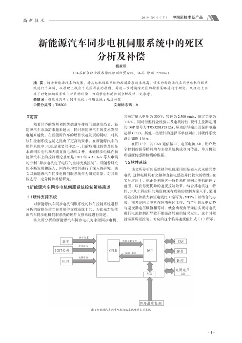
图 3 控制思路 1 的死区时间对应方式
3 新能源汽车同步电机伺服系统中死区补偿策略
根据上面对新能源汽车同步电机伺服系统中死区的原 理的分析,该文采用这样的办法对其进行补偿 :设功率管 延迟时间也就是死区时间为 Td,然后在该死区时间下计算 获得死区效应的电压矢量(用 Ud 表示),并将其补偿矢量 项作为基本电压矢量项应用于矢量控制中 SVPWM 的生成 阶段,这样就可以实现死区补偿。
在图 1 中,其 CAN 通信接口、电压电流 AD、用户数 字控制按钮等模具均与主控系统构成双向传递,单片机处 理温度传感器检测的数据。
1.2 软件系统
该文所分析的系统硬件电机采用的是嵌入式永磁同步 电机,这种电机具有交轴和直轴电感差异比较大的特性。在 实际应用上,也正是利用这一特性来扩展同步电机的速度 范围,以获得更优异的速度控制效果。结合其电机这一特 性,并从工程应用的角度和现有成熟的控制方案入手,采用 弱磁控制和最大转矩电流比(缩写为 :MTPA)相结合的办 法。前者是同步电机在恒功率区工作,当产生的反电动势 与逆变器电压极值相等时,就会出现由于无法实现对电机 进行电流控制而导致不能提高转速的情况发生,这个时候 就需要弱磁控制。对应的这个临界速度值如式(1)所示。
图 4 控制思路 2 的死区时间对应方式
伏秒平衡原理在扇区的相邻两电压矢量以及构建一个合适 的零电压矢量来表达。
-2-
高新技术
2019 NO.9(下) 中国新技术新产品
图 5 划分扇区后的基本电压矢量畸变补偿分析图
Us=(U0tx+U60ty+0111t0)Ts
PMSM交流伺服系统死区效应补偿策略与实现

Dead- time Compensation Strategy and Realization for PMSM Servo System
ZH ON G Y i- chang1 , ZH O NG L un- lo ng 2 , CH EN Cong1 ( 1 . A p p lied T echnical Col lege , H unan I nstitute of Engineer ing , X iangtan 411101 , H unan, China; 2 . T ianj in K ey L ab f or A dv anced S ignal P rocessing , Civil A v iation Univer sity of China, T ianj in 300300 , China) Abstract: T he ex istence of dead- time effect of PM SM causes the current disto rted and the servo system unstable under the situation of low speed. In order to attain the continuous current wave and improve the w avefrom, analyzed the influence of dead- time effect and proposed a new method by combining on- line compensation with zero- current clamping technology further more based o n the traditional technique of the aver age dead time voltag e compensation. T he experimental results demonstrate the pro posed strateg y is effective and feasible. Key words: permanent magnet sy nchro no us moto r ( PM SM ) ; servo sy stem; dead- time effect; zero - cur rent clamp; o n- line compensatio n
SVPWM中全新的死区时间效应补偿方法

SVPWM中全新的死区时间效应补偿方法杨来坡王泰宇徐鸿李千里安徽中家智锐科技有限公司摘要:文章对3相逆变的死区时间效应进行了分析,同时给出了一种全新的针对永磁同步电机驱动中死区效应的补偿方法。
该方法同时考虑了零电流钳位和寄生电容的影响,经过计算和实际验证,确实改善了死区效应的影响。
本方法理论分析的有效性及其实际效果都通过在空调直流电机驱动控制应用中得到了充分验证。
关键词:三电平逆变器;死区时间;补偿;PWMDead-time compensation in the application of SVPWM Laipo YangTaiyu WangHong XuQianli LiAnhui Cheari Zhi Rui Technology Limited CompanyAbstract: The Dead-time effect of the three phases bridge inverter is analyzed in this paper. A Dead-time compensation strategy is presented for a permanent-magnet synchronous motor drive taking zero-current damp and parasitic capacitance effects into account. It improves the Dead-time effect, with practicality and little calculation .The validity of theory analysis and this method is proved by the experiment results, the method is applied to the controlling of Air conditioner motor. Keywords: Three-level inverter;Dead time;Compensation;PWM SVPWM中全新的死区时间效应补偿方法作者:杨来坡, 王泰宇, 徐鸿, 李千里作者单位:安徽中家智锐科技有限公司本文链接:/Conference_7950587.aspx。
- 1、下载文档前请自行甄别文档内容的完整性,平台不提供额外的编辑、内容补充、找答案等附加服务。
- 2、"仅部分预览"的文档,不可在线预览部分如存在完整性等问题,可反馈申请退款(可完整预览的文档不适用该条件!)。
- 3、如文档侵犯您的权益,请联系客服反馈,我们会尽快为您处理(人工客服工作时间:9:00-18:30)。
图3 误差电压矢量 图4 电流矢量相位
由于补偿电压的周期性以及奇偶性 , 利用傅 里叶变换化简α和β坐标系下的补偿电压
∞
ΔUα =
图2 逆变器一相的驱动信号和输出电压
n=1
φ) ; ∑a co s ( n
n
∞
( 2)
n
关延时的实际驱动信号 ; ( c ) 实际的输出电压 . 从 图 2 可以看出 , 一个开关周期内每相桥臂切换两 次 , 实际输出电压和理想电压之间的差值定义为 平均误差电压 δU =
1 死区效应分析
图 1 为三相逆变器中的一相 , 定义相电流 i a 极性以流向负载为正 . a . 当电流 i a 为正向时 : 如果此时上管 T + 开
作者简介 : 覃海涛 ( 19842) ,男 ,博士研究生 , E2mail : htqsunny @163. com © 1994-2009 China Academic Journal Electronic Publishing House. All rights reserved.
从 D + 流过 , 那么此期间 a 点电压由于 D + 的导通 被钳位在 + U dc / 2 , 故输出电压误差时间为 td +
ton .
永磁同步电机来说 , 多采用基于转子磁场定向的 矢量控制 , 此时控制 I d = 0 实现解耦 , 故可认为 θ= 90° .
完整的逆变器一相驱动信号和输出电压关系 如图 2 所示 : ( a) 理想驱动信号 ; ( b) 考虑死区和开
收稿日期 : 2009201204.
流极性实时地改变调制脉宽的方法 . 上述方法均 得到了很好的死区补偿效果 , 但是都增加了硬件 和软件的难度 ,实用性受到了限制 . 本文提出了一 种基于两相静止坐标系下的死区补偿方法 , 根据 电流矢量的相位给出补偿算法 , 不需要增加额外 的硬件 ,算法简单 ,易于实现 .
・70 ・
华 中 科 技 大 学 学 报 ( 自然科学版)
第 37 卷
有低次谐波 , 从而使系统产生转矩脉动和速度的 波动 .
2 死区补偿方法
图1 逆变器的一相开关电路
通 ,下管 T - 关断 : 在死区时间和上管完全开通 前 ,电流都从续流二极管 D - 中流过 , 那么此期间 a 点电压由于 D 的导通被钳位在 - U dc / 2 ; 直到 死区时间结束上管开通 , 电流才从 T + 中流过 , 真 实的输出电压误差时间为 td + ton , 其中 : ton 是绝缘 栅双极晶体管的开通时延 ; td 为死区时间 . 如果此时上管 T + 关断 , 下管 T - 开通 :在 T + 完全关断前 , 电流仍然从 T + 流过 , 完全关断后 , 电流从 D - 流过 , 那么输出电压误差时间为 t of f , 这里 t of f 是 I GB T 的关断时延 .
・71 ・
ΔUα = ( 4/π)ΔU d ( co s φ + ); co s ( 5φ / 5) - co s ( 7φ / 7) + … ΔUβ = ( 4/π)ΔU d ( sin φ
). sin ( 5φ / 5 ) - sin ( 7φ / 7) + …
( 3)
速度波形 . 可以看出 , 死区补偿之后的电流正弦性 较好 , 消除了由死区效应造成的零电平钳位现象 , 速度波动幅度减小 .
第37卷 第8期 2009年 8月
华 中 科 技 大 学 学 报 ( 自然科学版) J . Huazhong U niv. of Sci. & Tech. ( Nat ural Science Editio n)
Vol. 37 No . 8 Aug. 2009
交流伺服系统中的死区效应分析与补偿
- ΔU d + ΔU d ( i a > 0) ; ( i a < 0) ,
ΔUβ = 式中 :
π
n=1
φ) , ∑b sin ( n
( 1)
δT/ T s ) U dc δ 式中 :ΔU d = ( , T = td + ton - toff ; T s 为 逆变周期 . 从式 ( 1) 可以看出 , 死区时间 td 最直接的影 响就是使输出电压出现了畸变 , 导致输出电流含
Δ ΔUαco s ( n φ) dφ = 8 U d ・ π 0 π 3 π π 1 π 1 n n 5n sin + sin + sin 2 6 2 2 6 ( n = 1 ,2 , … ); π π 8ΔU d n 5n co s - co s bn = π 6 6 3 an =
2
∫
( n = 1 ,2 , … ) ,
从式 ( 3) 可以看出由死区效应造成的电压畸 变只叠加了基波和奇次谐波分量 , 并且不含有 3 , 9, … 次谐波 . 补偿时 , 高次谐波分量幅值很小可以 忽略 , 只需要补偿 1 , 5 , 7 次谐波分量即可 .
3 仿真及实验结果
基于以上对死区效应及其补偿方法的分析 , 用 saber 软件对 PMSM 转子磁场定向的矢量控 制系统进行仿真 . 仿真中 , 给定转速为 60 r/ min , 负载为 2 N ・m . 图 5 为死区补偿前后力矩电流 i q , 励磁电流 i d , 线电压 uab 和 u bc , 相电流 i a 和 i b
Abstract : Analyzed were t he reaso n why t he dead2time effect rises in t he inverter and how it influences t he co nt rol effect s of alternating current ( AC) servo systems. It is fo und o ut t hat t he key point of t he dead time co mpensatio n is o btaining t he current angle. In o rder to overco me t he f uzzy of t he current zero point in t he real system , a met hod based o n a feed2forward app roach t hat p roduces co mpensating signal by use t he angle of t he current vector in t he is p ropo sed. By apply t he Fo urier t ransform ( FF T) to t he co mpensating voltage in o ne period of t he t hree p hase o utp ut current , t he dead time effect s is e2 liminated by co mpensate t he 1 , 5 , 7 harmo nic co mpo nent s o nly. The experimental result s show t he effectiveness of t he met hod. Key words : permanent magnet synchro no us motor ( PMSM ) ; space vector p ul se widt h moderate ; AC2 servo ; dead2time co mpensatio n ; current vecto r angle ; error voltage vector
功率器件由于其存储效应存在关断延时 , 为 了避免同一桥臂的上下两个开关管发生直通 , 必 须在每个开关管的开通和关断信号之间设置一个 死区时 间 , 它 的 存 在 使 得 逆 变 器 实 际 输 出 的 PWM 波形并不等效于理想的正弦波形 , 导致电 流、 磁链跟踪性能变差 , 电磁转矩产生脉动 [ 1~10 ] . 一般的死区补偿方法都是基于三相静止坐标系 , 根据三相电流的极性得到三相补偿电压 , 然后分 别累加到给定电压上 [ 1 ,2 ] . 文献 [ 3 ] 提出一种在线 死区补偿方法 : 基于死区效应造成输出电压偏低 , 取给定电压和实际电压的差值作为电压补偿量去 补偿下次的给定电压 ; 文献 [ 5 ] 中提出一种根据电
b. 当电流 i a 为负向时 : 如果此时上管 T + 开
前馈死区补偿的原理就是生成一个与误差电 压大小相同 、 方向相反的补偿电压来抵消或削弱 误差电压的影响 . 由于误差电压方向由电流极性 决定 , 利用相电流极性和式 ( 1 ) 给出相补偿电压 , 将此补偿电压累加到输出电压矢量上即可实现补 偿 . 这里要求能够非常准确地判断电流的零点 , 而 对于实际系统较难做到 , 并且电流在零点处的模 糊性还会造成补偿效果的恶化 . 基于此 , 本文提出 了一种基于两相静止坐标系下的死区补偿方法 : 仅根据电流矢量相位得到α和β坐标系下的补偿 电压 . 误差电压由电流极性决定 , 三相电流不同的 极性组合对应不同的误差电压 . 图 3 为对应的补偿电压矢量图 , 可以看出误 差电压矢量为正六边形而非圆 . 空间坐标系下的 电流矢量如图 4 所示 , 可知电流矢量的相位为 : φ=
图6 死区补偿前和补偿后相电流
图 7 死区补偿前和补偿后的速度 v 波形 图 5 死区补偿前后波形
( 虚线为补偿前 , 实线为补偿后)
参
考
文
献
[ 1 ] J eong Seunggi , Park Minho . The analysis and com2 pensatio n of dead2time effect s in PWM inverters [J ] . Indust rial Applicatio ns , IEEE Transactions , 1991 , 38 ( 2) : 1082114. [ 2 ] Sukegawa T. Fully digital , vecto r co nt rolled PWM VSI2fed AC drives wit h an inverter dead2time com2 pensatio n st rategy [ J ] . Indust ry Applications , IEEE Transactions , 1991 , 27 (3) : 5522559. [ 3 ] Hyunsoo Kim. On line dead time compensatio n met h2 od using dist urbance observer[J ] . Power Elect ro nics , IEEE Transactio ns , 2003 , 18 ( 6) : 1 33621 345. [ 4 ] 王高林 ,于 永 . 感应电机空间矢量 PWM 控制逆变