CH1 Pag1-Pag10
Parker Hannifin PL10胶油器产品说明书
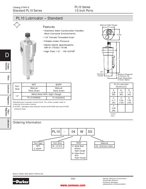
PL10 Series1/2 Inch PortsCatalog 0700P-EStandard PL10 Seriesof Drain Option Ordering InformationPort Type- NPTG BSPPPort Size04 1/2 InchMaterialSS Stainless SteelPL10 - 04 W SSBOLD ITEMS ARE MOST POPULAR.PL10 LubricatorDimensionsA2.36(60)A12.52(64)B1.73(44)C2.17(55)D5.46(139)E7.62(194)F3.50(89)inches(mm)Features• Stainless Steel Construction HandlesMost Corrosive Environments• 1/8" Female Threaded Drain• Fillable Under Pressure• Meets NACE SpecificationsMR-01-75/ISO 15156• High Flow: 1/2" - 100 SCFM§BowlD Metal BowlwithoutSight GaugeW Metal BowlwithSight GaugePortSizeNPT BSPPManualTwist DrainManualTwist Drain1/2"Metal Bowl With Sight GaugePL10-04WSS PL10G04WSSStandard part numbers shown bold. For other models refer toordering information below.§ SCFM = Standard cubic feet per minute at 90 PSIG inlet and 5 PSIGpressure drop.012345P r e s s u r e D r o p - P S I GP r e s s u r e D r o p - b a r.1.2.3Primary Pressure - PSIG1.7 bar3.4 bar 5.2 bar 6.9 barPrimary Pressure - bar051015202530354045Flow - dm /s3nPL10 SeriesAir Line LubricatorsCatalog 0700P-E Technical Specifications – PL10PL10 Filter Kits & AccessoriesDrain Kit –Manual Twist Drain –Small (Old) ..........................................................SA600Y7-1SS Large (New) ...............................................................SAP05481 Pipe Nipple –1/2" 316 Stainless Steel ................................................616A28-SS Sight Dome Kit –(Old)..................................................................................RKL10SS (New) ..................................................................................PS740NSpecificationsBowl Capacity ..................................................................4.0 OuncesPort Threads ..........................................................................1/2 Inch Pressure & Temperature Ratings –Metal Bowl (D) ...................................0 to 300 PSIG (0 to 20.7 bar) 0°F to 150°F (-18°C to 66°C) Metal Bowl (W) ..................................0 to 250 PSIG (0 to 17.2 bar) 0°F to 150°F (-18°C to 66°C)Note: Air must be dry enough to avoid ice formation attemperatures below 32°F (0°C).OperationAir flowing through the unit goes through two paths. At low flow rates the majority of the air flows through the Venturi section (A). The rest of the air opens the check valve (C). The velocity of the air flowing through the Venturi section (A) creates a pressure drop. This lower pressure allows the oil to be forced from the reservoir through the pickup tube (B) and travels up to the metering screw (D). The rate of oil delivery is then controlled by adjusting the metering screw (D). Oil flows past the metering screw (D) and forms a drop in the nozzle tube (E). As the oil drops through the dome (F) and back into the Venturi section (A), it is broken up into fine particles. It is then mixed with the air flowing past the check valve (C) and is carried downstream. As the air flow increases the check valve (C) will open more fully. This additional flow will assure that the oil delivery rate will increase linearly with the increase of air flow.Technical InformationWeight ........................................................................1.9 lb. (0.85 kg)Materials of ConstructionBody .....................................................................316 Stainless Steel Bowl .....................................................................316 Stainless Steel Dip Tube ...............................................................316 Stainless Steel Drain ....................................................................316 Stainless Steel Fill Plug ................................................................316 Stainless Steel Seals .............................................................................Fluorocarbon Sight Dome ...............................................................................Nylon Sight Gauge ........................................................................Isoplast(Revised 11-21-12)Stainless Steel FRLs Catalog 0700P-ENotes。
G10的用法

G10可编程参数输入G10允许用户在程序中设置偏置,用G10代替手工输入刀具长度偏置、半径补偿、工件坐标系偏置等。
G10L_P_R_X_Y_Z_L:选择的偏置种类L2G52和G54-G59工件坐标原点。
L10刀具几何页面长度偏置(H代码)L11刀具磨损页面长度偏置(H代码)L12刀具几何页面半径补偿(D代码)L13刀具磨损页面半径补偿(D代码)L20G110-G129辅助工件坐标原点P:选择的特殊偏置,由于P是跟随在L后面的选项,在不同的L种类中P的含义不同。
L10/L11中:P1-P100用来指定刀具长度补偿H代码。
G10L10P1…P1表示H01L12/L13中:P1-P100用来指定刀具半径补偿D代码。
G10L12P1…P1表示D01L2中:P0、P1-P6用来表示基本偏置EXT、G54-G59工件坐标系。
(P1=G54、P2=G55、P3=G56、P4=G57、P5=G58、P6=G59)G10L2P0…P0表示EXT基本坐标系。
G10L2P1…P1表示G54工件坐标系。
L20中:P1-P20用来表示G110-G129辅助工件坐标系。
(P1=G110、P2=G111、P3=G112……P19=G128、P20=G129)L20中:P1-P99用来表示G154P1-G154P99参考工件坐标系。
R:长度或直径偏置量的绝对值或相对量。
L10中:R用来表示长度偏置的绝对值。
G10L10P1R100.3表示长度H01里面输入100.3L11中:R用来表示长度偏置的增量值。
G10L11P1R2.1表示在原有的长度H01里面增加2.1L12中:R用来表示半径偏置的绝对值。
G10L12P1R4.1表示半径补偿D01里面输入刀补4.1L13中:R用来表示半径偏置的增量值。
G10L13P1R-0.1表示在原有的半径D01里面减去0.1*L10/L11为加工中心特有的偏置类型,不适用于车削**R值可以叠加使用,例如:G10L10P1R100.3G10L11P1R2.1运行该程序段后刀具长度补偿偏置里面实际值为102.4G10L12P1R4.1G10L13P1R-0.1运行该程序段后刀具半径补偿偏置里面实际值为4.0X_Y_Z_:仅在表示工件坐标偏置类型中,表示可以选择的X Y Z轴零点的位置。
Parker Hose 产品目录说明书
More of what you need to work smarter,AccessoriesV i s u a l I n d e x59RG D-17T1RG D-17Partek Sleeve D-18ParKoil™ (PG) D-19GuardsO-Rings for CA, CE,CF MetricFlange “D” Rings Caterpillar ® Style FlangesT ube O-Ring Fittings and CompressorFittingsO-Rings for Compression Fittings (IT126)O-Rings for C9, OC, 1C Metric Swivels88HC-H Clamp D-2488DB Clamp D-24Hose Assembly D-26Workstations3/4 Reel Rack D-2772B-Cabinet D-28HR6 Hose Bin D-28Hose Adapters D437° Flare Metric Triple-Lok ®Sizes: 6 mm – 38 mmMaterials : Steel, Stainless Steel Pressures : Up to 7200 psi60° Cone BSPPK4Sizes : 1/8” – 2”Materials : Steel Pressures : Up to 5000 psi30° Flare Komatsu StyleSizes : M14 x 1.5 – M33 x 1.5Materials : Steel Pressures : Up to 4000 psiO-Ring Face-Seal Metric Seal-Lok™Sizes: 1/4” – 2”Materials: Steel, Stainless Steel Pressures: Up to 9200 psiJapanese Industrial Standard JISSizes : 1/4” – 1”Materials : Steel Pressures : Up to 5000 psiWhen ordering Parker Adapters, please state the Catalogued Number of each type of adapter desired. Be sure to double check tube and hose sizes of items required.To select proper seal materials for specific applications, refer to Media Compatibility Chart in Tube Fitting Catalog 4300, or contact your Parker Tube Fitting Distributor.If in doubt about which type or size of fitting to specify, consult your Parker Tube Fitting Distributor. In addition Parker Field Sales, Technical Services,the Tube Fitting Division and your local Parker Service Center will help you find answers to all your issues.Phone: (614) 279-7070Fax: (614) 279-7685Web: /tfdNote: Refer to Parker Catalog 4300 for more detailed application information.CALL TOLL-FREE 1-800-C PARKER (1-800-272-7537)Parker Information Center for catalogs, literature or additional information.O-Ring Face-Seal Seal-Lok™ Sizes: 6 mm – 38 mm Materials: Steel, Stainless Steel Pressures: Up to 9200 psi37° Flare FittingsTriple-Lok ®Sizes: 1/8” – 2”Materials: Steel, Stainless Steel, BrassPressures: Up to 9000 psiPipe Fittings and Port AdaptersSizes: 1/8” – 2”Materials : Steel, Stainless Steel, BrassPressures : Up to 7200 psiPipe SwivelsSizes : 1/8” – 2”Materials : Steel, Stainless Steel Pressures : Up to 5000 psiConversion AdaptersSizes: 1/4” – 1-1/2”Materials : Steel, Stainless Steel Pressures : Up to 7700 psiHydraulic Flange and Flange AdaptersSizes : 3/4” – 3”Materials : Steel, Stainless Steel Pressures : Up to 6000 psi15T3SAE (Code 61) Flange – Male SAE (JIC) 37˚ FlareCaution: Do not use the T3 flange to tube or swivel nut to tube adapter in hose assembly applications inwhich pressures exceed the SAE100R2 working pressure range.17T3SAE (Code 61) Flange – Male SAE (JIC) 37˚ Flare - 45˚ Elbow19T3SAE (Code 61) Flange – Male SAE (JIC) 37˚ Flare - 90˚ Elbow39T3Male - Female Swivel - SAE (JIC) 37˚ - 90˚ Elbow41T3Male - Female Swivel - SAE (JIC) 37˚ - 90˚ Elbow - Long4AH3SAE Code 61 Flange - Male SAE (JIC) 37˚ Flare - 5000 psi Caution: Do not use the T3 flange to tube or swivel nut to tube adapter in hose assembly applications in which pressures exceed the SAE100R2 working pressure range.4FH3SAE Code 61 Flange - Male SAE (JIC) 37˚ Flare - 5000 psi -45˚ Elbow4NH3SAE Code 61 Flange - Male SAE (JIC) 37˚ Flare - 5000 psi -90˚ Elbow6AH3SAE Code 62 Flange - Male SAE (JIC) 37˚ Flare6FH3SAE Code 62 Flange - Male SAE (JIC) 37˚ Flare - 45˚ Elbow4AJMCode 61 Flange - Male Seal-Lok4FJMCode 61 Flange - Male Seal-Lok - 45˚ Elbow4NJMCode 61 Flange - Male Seal-Lok - 90˚ Elbow6NH3SAE Code 62 Flange - Male SAE (JIC) 37˚ Flare - 90˚ Elbow6NJMCode 62 Flange - Male Seal-Lok - 90˚ Elbow6FJMCode 62 Flange - Male Seal-Lok - 45˚ Elbow6AJMCode 62 Flange - Male Seal-LokNote:*5000 psi with 4A, 4F and 4N Fittings and 50H Flange Halves.There are two non-interchangeable SAE split flanges: a: S tandard or Code 61 is for 3,000psi to 5,000psi maximum, depending on size.b.H igh Pressure or Code 62 is for 6,000psi maximum, r egardless of size. The flange head is “V” notched for identification.Consult these tables to determine flange halves and flange kits specifications.High Pressure (Code 62)Standard Pressure (Code 61)Note: For use with 4A, 4F and 4N Flanges.50H5000 psi Flange Half (Code 61)Note: For use with 4A, 4F and 4N Flanges.Note: High pressure applications also require the use of Code 61 Flange End hose fittings.51HSAE Flange Half (Code 61)5050HK5000 psi Flange Kit (Code 61)5151HKSAE Flange Kit (Code 61)HFHSAE Flange Half (Code 62) HFHFHKSAE Flange Kit (Code 62) 8FHFlange Half (8000 psi)8FHFHKFlange Kit (8000 psi)DIN and ISO Metric PortsDIN (German) and ISO (International Organization for Standardization) flange heads are the same as SAE flange heads. By comparison, the ports have the same configura-tion except that the DIN and ISO Type I ports accept metric bolts. This requires specialflange halves in most sizes.Note: High pressure applications also require the use of Code 62 Flange End hose fittings.M1HDIN (ISO) Flange HalfM1M1HKDIN (ISO) Flange Kit (Code 61)M2M2HKDIN (ISO) Flange Kit (Code 62)M2HDIN (ISO) Flange Half (Code 62)711509O-Rings - SAE Thread (Compound N552-90)*711510O-Rings - Code 61 and Code 62 Flanges (Compound N552-90)**Note: F or use with petroleum base fluids, other compounds available for Phosphate Ester fluids.Please contact The Parker Hannifin Seal Group/O-Ring Division (1-800-C-PARKER) for additional information.C9RG O-Rings for CA, CE, CF MetricC9RG O-Rings for C9, OC, 1C Metric SwivelsD9DTBonded Seal for BSPP Port Fittings*Note: D 9DT must be ordered from the Tube FittingsDivision. Please contact TFD for additional size and product information.XARGFlange “D” Rings Caterpillar ®Style FlangesJ0RGO-Rings - Seal-Lok ®Note: O -Rings for use in Seal-Lok ® connections are illustrated in actual size. Part numbers for O-Ringsused in Seal-Lok ® and in SAE port connections are also listed in the table. O-Rings are supplied in Nitrile NBR compound, 90 durometer hardness.SAE 711509-4-8Seal-Lok J0RG-8-8Photo shows an actual comparison between an SAE port O-Ring (top) and a Seal-Lok ® O-Ring (bottom). They differ in both diameter and cross section.8ARGFlange “D” Rings for 76 Series Style FlangeT1RGO-Rings for Compression Fittings (1T126)Charge Ports CapsR134aR12CORGCaptive O-Ring Assembly ToolsParker’s new CORG Assembly Tools are designed to facilitate the installation of the O-Ring into the half-dovetail groove of the O-Ring face seal fitting.Note: C ORG Assembly T ools must be ordered from the T ube Fittings Division (614) 279-7070.Note: O -Rings listed are for use with petroleum base fluids. Other compounds are available for Phosphate Ester fluids by special order. For Viton ® or otherO-Ring compounds, consult Parker Hannifin, Seal/O-Rings Products Division (1-800-C-PARKER.)Bench TypeHand Type59RGO-Rings for Tube O-Ring Fittingsand Compressor FittingsNote:T he above O-Rings (RG) have HNBR compound number N1195-70 (green).Accessory Selection Guide – Partek Sleeve (AS-B, AS-Y or PS)Note: T he inside flat “A” dimension correspondswith the inside diameter “B” dimension. For example, AS-Y -13 flat surface “A” is 1.34 in. This offers a .86 in. inside diam-eter “B”. Hose with a smaller O.D. can be specified for this size sleeve. Parker 201-5 hose has a .58 in. O.D. and can easily be inserted in the Partek AS-Y -13Sleeve.Note: 1. T he dimensions shown are related to the hose outside diameter and may not fit over the fitting. For over the fitting applications, a larger sizesleeve may be required.2. Cut lengths are available. Contact your local distributor for prices ().Partek SleevePartek “PS” SleeveParker’s Partek Nylon Protective Sleeving gives you tough hose abrasion protection two ways. First, per the ISO 6945 specification, Partek has a unique tubular weave nylon construction, Partek “AS” is strong enough to withstand greater than 200,000 abrasion cycles without wearing through the fabric at any loca-tion. Partek “PS” can withstand greater than 50,000 abrasion cycles. In addition, this weave also gives an exceptionally smooth interior wall, allowing rubber hose to move freely inside the sleeve. This provides easy installation and prevents any internal abrasion problems. Partek sleeving is available in either black or yellow and in sizes to fit most hydraulic hose. Partek, the quick and easy solution to hose protection in high-abrasion areas.Temperature Range: -67°F to +248°F (-53°C to +120°C)Accessory Selection Guide – PolyGuard (HG)• S hield hose from abrasion and cuts • Minimize kinking• Cannot rust or corrode • R esist water, oil, gasoline, hydraulic fluid, and most solvents • I deal for bundling plastic tubing or hose lines • E asy to install without removing hose lines; no clamps neededPolyGuardHeavy-duty polyethylene provides protection in rugged operating conditions.Great for b undling high-pressure hose lines.Cut edges can be smoothed by applying heat.CAUTION: This material will support combustion.Color: BlackTemperature Range:0˚F to +200˚F (-17˚C to +93˚C)Parkoil ™Lower-cost protection for applications that call for a tighter bend radius and are less demanding.Cut edges can be smoothed by applying heat.CAUTION: This material will support combustion.Color: BlackTemperature Range:0˚F to +200˚F (-17˚C to +93˚C)Accessory Selection Guide – ParKoil ™ (PG)Accessory Selection Guide – Spring Guard and Armor GuardNote:Spring Guard and Armor Guard are packaged in 10 ft. pieces.Parker Spring Guard and Armor Guard are two products that prolong the life of hose lines that are exposed to rugged operating conditions. They distribute bending radii to avoid kinking in hose lines and protect hose from abrasion and deep cuts. Guards areconstructed of steel wire and plated to resist rust.Spring Guard (SG)Armor Guard (AG)Accessory Selection Guide – Firesleeve (FS-F)Parker Firesleeve is a flame resistant sheath that protects the hose from extreme temperature conditions. Firesleeve easily slides over hoses and readily expands over fitting. It can be assembled with Parker FSC or properly sized wormgear clamp.Construction: Braided fiberglass sleeve and an orange,bonded and seamless silicone rubber cover.Specifications: Conforms to SAE Aerospace Standard 1072A Type 2A.Temperature Range:-54˚C to +260˚C (-65˚F to +500˚F).Note: T he Firesleeve inside dimension (I.D.)must exceed the outside diameter (O.D.) of the hose and offer an allowance for easy hose insertion. For example, 201-16 has a 1.23 in. O.D. FS-S-24, with an I.D. of 1.46 in., is the suggested Firesleeve. Note: P arker FSC Clamp fits all hoses up to2 in. O.D. Note: P arker HC Clamps (wormgear) are listedon page D-24.Note: See Page D-22 for Firesleeve assembly instructions.Firesleeve (FS-F)FSC ClampPart Number: FSC(One size fits all hoses up to 2 inch O.D.)Accessory Selection Guide – Firesleeve (cont.)1. A ssemble one end fitting on hose. Cut firesleeve to same length as hose. Cover approximately 1” of each end of fire-sleeve with FSS sealant and allow to dry.2. P ush firesleeve back from cut end of hose and assemble the second end fitting. Then pull firesleeve completely over both sockets.3. I nsert tail of FSC clamp into FST clamping tool.4. P osition clamp around middle of socket and tighten with tool. Bend end of band back over buckle. Repeat on other end.Repair any scuffs or abrasions in firesleeve with FSS sealant.FSC ClampUsed to attach firesleeve around socket on hose sizes with a 2” maximum O.D.FST Clamp ToolPart Number: FST -711617 Used to secure FSC clamp.FSS Firesleeve SealantKeeps end of firesleeve from fraying - for neater, longer lasting installation.FiresleeveAssembly InstructionsAccessory Selection Guide – CL ClampVinyl coated steel clamps provide hose support where long lengths are used. Provides neater installation of hose lines, minimizes hose chafing and prevents damage to hose.Material: CR Steel with Zinc PlatingCoating: Black Vinyl Plastisol - 0,8 mm (0.03 inch) thick.Temperature Range:-40°C to +107°C (-40°F to +225°F).Accessory Selection Guide – HC, 88HC-H and 88DB ClampThe Parker HC Clamp is a stainless steel worm gear clamp designed for low presure industrial hose applications.Material: Stainless steelSpecifications: SAE J1508, Type F and Type HD88HC-HSeries Hose Clamp(High Torque Wormgear)88DBSeries Heavy Duty Hose Clamp(Double Bolt Hose Clamp)HC Hose Clamp TableNote: See 88 Series Assembly Instructions for proper 88HC-H clamp attachment.Accessory Selection Guide – Protection Shields (HP , HT, and HP-B)Prevent hose abrasion while extending your hose life. Parker Hose Protection Shields extend hose life by protecting the hose from abrasion that occurs when hose rubs against other hose, metal or concrete. Parker hose shields are resistant to oil, lubricants, gasoline, most solvents and can withstand ambient temperatures from -40° to +300° F . Easily installed and secured by cable ties without disconnect-ing any hose lines. Use with hose from 1/4” to 2” I.D.♦ Eliminate hose abrasion on concrete, metal or any rough surface. ♦ Guard against hose deterioration on mobile hydraulic equipment. ♦Let Parker fill all your hydraulic and pneumatic hose product needs.Hose Protector Shields are a fast and extremely cost effective way to isolate fluid lines from direct contact with other lines, components or structural members. They’re available in 4-inch, 6-inch and 8-inch lengths and the width can be trimmed to satisfy a variety of situations. These flexible protectors simply clamp around the hose and are securely held in place by nylon cable ties which are included. The cable ties are recessed in molded grooves to protect them from abrasion. You don’t need to disconnect a line to install a Parker Hose Protector Shield the way you do with a continuous tubular sleeve. Just wait until the installation is up and running to see exactly where contact needs to be prevented.Parker Hose Protector Shields are available in bulk quantities and in convenient assortments in 4”, 6” and 8” sizes. Cable ties are included with all protectors and are also available in bulk.Hose ShieldsTie Wraps HP-B-13X18-KIT2 ea. HP-13 RFL HT -12-KIT 30 ea. HT -12 Tie Wraps 2 ea. HP-15 RFL HT -16-KIT 30 ea. HT -16 Tie Wraps4 ea. HP-18 RFLHT -22-KIT15 ea. HT -22 Tie Wraps20 Hose Protectors and 60 Tie Wraps for each size are in point of purchase display box.HP-B-13-RFL 10 ea. HP-B-13 Hose Protectors (4”). 30 ea. HT -12 Tie Wraps in a sealed plastic bag.HP-B-15-RFL10 ea. HP-B-15 Hose Protectors (6”). 30 ea. HT -16 Tie Wraps in a sealed plastic bag.HP-B-18-RFL5 ea. HP-B-18 Hose Protectors (8”). 15 ea. HT -22 Tie Wraps in a sealed plastic bag.Contact your authorized Parker Hose Products Distributor for pricing and delivery information.Note: Parker Hose Protector Shield products are intended to prevent damage. They are not suitable as patches or repairs for lines which are already damaged or worn beyond safe use standards.Counter DisplayThe complete on-site complete hose assembly workstation design (above) includes:• TH7-5-C—6’ table with 1 hose reel and 1 bottom shelf • TH7-6—16 hose reel system, with rotating base • T H7-7—15” wide table set up for Parker 239 or 339 Cut-Off Saw Specifications: HoseFab Table (heavy duty)• Laminated wood table top • 1-1/2” square tubing structure • Gussetted corner braces • 6-leg design• All legs have adjustable feet • Hose reel/shelf combinations• 40B-Cabinet or 72B-Cabinet for fitting storage • Optional: Hose trough for measurement of hose • Calibrated to line up to Saw Table • Adjustable stop for standard length cuts• Built-in tape measureSpecifications: Rotary Reel Rack (TH7-6)• 16 Hose reel capacity • Compact design• Rotates for 1 man use• Center post bolts to floor in 4 places • Optional: Overhead craneSpecifications: Saw Table (TH7-7)• Calibrated to line up to Hose trough • Adjustable feet• Mounts to 6-foot benchSpecifications: 3 or 4 Reel Rack • Free standing 3 reel rack (TH7-8)• Bolts to floor• Optional: 4th reel capacity with wall mounts (TH7-8-F)• (2) 40B-Cabinet 40 openings - 4·1/2” x 4·1/2” x 12” in size • TH7-6-C—Optional overhead crane • T H7-5-HT—Optional 6’ measured hose trough with ad -justable hose stopPictured left is a complete on-site hose assembly workstation, the Parker Kart:The Parker Kart, TH7-4, is a portable all-in-one unit designed to hold a Minikrimp, Karrykrimp, Karrykrimp 2, or Parkrimp 1; a 332T -115V Cut-off Saw; 4 reels of hose; and has a 40 bin cabinet with 3 drawers for tools. The TH7-4 can be customized to fit your specific hose assembly needs. Contact Parker HPD or your Parker Hose distributor for details.Note: Part number TH7-4 does not include hose, fittings or equipment.Note: Part number and specifications of components for both workstations are listed on the following pages.HPD Hose Assembly WorkstationsHose Products Division has set up an agreement to allow Hose Products customers to purchase directly from our vendor, Safety Step.Safety Step’s contact information is:Safety Step Annette Cox 888-448-4237*********************See Safety Step contact information at the top of this pageSaw TableFeaturesThe Saw Table, specially designed for Parker 239 or 339 Hose Cut-Off Saw, attaches directly to the HoseFab Table.Part Number DescriptionTH7-715” wide table set up for Parker 239 or 339 Cut-Off Saw Table measurements:H eight - 18” Width - 28”Length - 14”3/4 Reel RackFeaturesCompact in its design, the standard version will hold 3 reels of hose. Optional 4th reel capacity designed with wall anchor mounts.P art Number DescriptionTH7-8 Upright 3 hose reel rackTH7-8-FO ptional extension with wall anchor for 4th reel Rack measurements:Height - 59” (82·1/2” with 4th reel option) Width - 27·3/4”Length - 27·1/2”HoseFab TableFeaturesHeavy duty constructed table for mounting Minikrimp, Karrykrimp, Karrykrimp 2, or Parkrimp 1. HoseFab Table is available in 3 versions to meet your require-ments. Options include two 40B-Cabinets or 72B-Cabinets for fitting storage.Part Number Description TH7-5-R 6’ table with 2 hose reels TH7-5-S 6’ table with 2 bottom shelves TH7-5-C 6’ table with 1 hose reel and 1 bottom shelf TH7-5-HT O ptional 6’ measured hose trough with adjustable hose stop 40B-Cabinet 40 openings - 4·1/2” x 4·1/2” x 12” in size 72B-Cabinet 72 openings - 4·1/2” x 4·1/2” x 12” in size Table measurements: Height - 31-3/4” Width - 29”Length - 72”Rotary Reel RackFeatures16 Hose reel capacity that fits in a compact area. Supplied with heavy duty casters which allow for ease of turning, even when fully loaded. Optional overhead crane available.Part Number DescriptionTH7-6 16 hose reel system, with rotating base TH7-6-C Optional overhead craneRack measurements:Height - 104” (120” with optional overhead crane) Width - 67”Length - 67”See Safety Step contact information on page D-26See Safety Step contact information on page D-26See Safety Step contact information on page D-26See Safety Step contact information on page D-26Parker Kart Part No. TH7-4Parker Kart organizes and stores all your necessary Parker hoses, fittings, power and hand tools - everything you need to make fast hose assemblies on site. As a valued addition to any facility, Parker Kart will save on downtime and labor costs, as well as eliminate errors in cutting and fitting attachment. With Parker Kart, you’ll always have the materials you need, right when and where you need them.• Easy one-man movement• Eight-inch urethane casters with brakes• Forklift carry tubes• Electric receptable with cord• Fitting bins and drawers• Large tool drawer• Four hose reel holders• Choice of Parker crimping equipment• Optional accessories availableParker Kart can be customized to fit specific hose assem-bly needs. Parker Kart does not include hose, fittings orequipment.Fitting Stock Bins72B-Cabinet36” wide, 43” high, 12” deep, with 72 openings each 4-1/2”x 4-1/2” x 12”, heavy duty steel, all welded construction.Product bin labels are available.Hose Stock BinsHR6-Hose-BinRugged metal cabinet for stocking coils of Parker hose 36”wide, 28” high, 20” deep, with upright separators to provide6 compartments varying in width from 4” to 8”.Provides suitable base on which to place the fittings stockbin (top measures 36” x 20”, bottom of fittings bin measures36” x 12”.)Yellow with black “Parker Hose” lettering.See Safety Step contact information on page D-26。
Parker Chomerics CHO-BOND 1018和CHO-BOND 1019应用指南说明

1. This application procedure applies toParker Chomerics CHO-BOND® 1018and CHO-BOND® 1019. CHO-BOND1018, is a two-part nickel-platedaluminum polythioether and CHO-BOND 1019, is a two-part silver-plated aluminum polythioether, eachof which are typically used as gapfillers, fillets, and seam sealants.2. For New Applications: In a well-ventilated area, clean the surfaceswith isopropyl alcohol (IPA) and letthe solvent flash off. Other harshersolvents, such as methyl-ethyl-ketone (MEK), toluene, or acetonecan be used to clean more difficult toremove contaminants.For Rework Applications: removethe existing compound and preparethe surfaces same as above guid-ance.3. Once the surfaces are prepared,CHO-BOND 1018 or CHO-BOND 1019can be mixed. Refer to the MixingInstructions in this document aspresented on Page 2.4. CHO-BOND 1018 or CHO-BOND 1019material is now ready to be applied.CHO-BOND material is typicallypackaged in a 6-ounce (by volume)SEMCO® cartridge. CHO-BOND 1018is also available in a 2.5-ounce (byvolume) SEMCO cartridge.Note: The 6-ounce SEMCO cartridgewill require an application gun todispense the product. There aremanual guns as well as pneumaticguns. A commonly used pneumaticgun is the SEMCO model 250A. (Ap-plication guns are not available fromParker Chomerics). A typical illustra-tion of the 250A dispensing gun isshown in the next column:To initially select the proper pres-sure to dispense CHO-BOND prod-ucts from the SEMCO cartridge, setthe line pressure at 10 psi and thenactivate the dispensing gun. Whilethe gun remains activated, slowlyincrease the pressure to the gunsteadily until the CHO-BOND materi-al flows out of the gun at the desiredrate. Avoid having high pressure inthe line to limit unexpected excessmaterial.Care should be taken during the ap-plication of the CHO-BOND mate- rialso that any protective coating on thesubstrate is not damaged. A non-stick plastic applicator is a betterchoice than a metal one. Limiting thebead width to less than a ½-inch incross-section is recommended, asthe center of the bead may not prop-erly cure within the typical full-curetime period.5. When out of its container, andexposed to air, CHO-BOND 1018 /CHO-BOND 1019 material will startto cure with- in a few minutes. Asthe product starts to cure, it willbecome difficult to work with andmay compromise adhesion to themating surfaces. It is recommendedto dispense in short sections, ap-proximately 3 feet of working lengthat a time.Try to avoid applying a long beadof material where the beginning ofthe bead may start to cure beforeoptional forming and shaping cantake place.If forming or shaping of the materialis required, the forming tool shouldbe wet using Toluene (or other simi-lar slow evaporating solvents). Non-stick, inert, and chemically resistantplastic tools may be a better choicethan a metal forming tool to avoidinadvertent damage to the substrateor finish. CHO-BOND 1018 and CHO-BOND 1019 will feel gritty duringapplication and forming, due to thelarge particle size of the conductivefiller.6. Handling time will vary by applica-tion. Typically, the assembly can behandled after 24 hours of cure time.The assembly will continue to cureas long as there is access to the am-bient atmosphere. Ideal conditionsfor full cure are room temperature21± 11°C (70± 20°F). Cure is inde-pendent of relative humidity levels.CHO-BOND® 1018 & CHO-BOND® 1019 Application Guide1. Always read and understand theprocess specification and the Safety Data Sheet (SDS), which provides information on health, physical and environmental hazards, handling precautions and first aid recommen-dations.2. Remove red nozzle cap and screw indasher rod (clockwise) into propel-ler mixer located inside the nose of cartridge.3. Hold cartridge, grasp dasher rod,and push forward approximately one inch.4. Insert ram rod into hollow of dasherrod, break piston loose, and inject about one-third of the contents into the front third of the cartridge.Note: Use even pressure; do not use force, tap, pound, or jolt ram rod if piston does not break loose readily.5. Push forward dasher rod and injectone-third of the rod’s contents at the middle of cartridge, then push dasher rod and inject the last third one inch from the end of the car-tridge. Remove ram rod.6. To mix, hold cartridge and pushdasher rod to the plunger end. Begin stroking the dasher rod turning in a spiral clockwise motion from the end of the cartridge to the plunger. Rotate the dasher rod approximately 90 degrees each stroke. A stroke is one complete in and out cycle. Mix material to 60-120 strokes (approxi-mately 1-2 minutes), or until well mixed.7. After mixing, remove red bottom/end cap.8. Pull dasher rod back to the nose ofthe cartridge. Grasp cartridge firmly at the neck, unscrew dasher rod and remove.9. Screw dispense nozzle into car-tridge. The dispense nozzle can be cut at an angle to help form the de- sired bead size and shape, reducing the amount of shaping and forming of the dispensed bead.Mixing Instructions - Injection Style Cartridge PackageDasher RodDispense NozzleRam RodSEMCO TubePropeller Mixer(internal)CHO-BOND® 1018 (Ni/Al filler) and CHO-BOND® 1019 (Ag/Al filler) caulking compound kit consists of a (part-A binder), charged in a HPE SEMCO tube, with a mixing dasher rod filled with part-B. The cartridge contains a propeller mixer inside the nose of the SEMCO tube. The mixing dasher rod is screwed on to the propeller mixer, and the contents of the dasher rod are “charged” into the SEMCO tube for mixing.10. Insert mixed and prepared tubeinto the dispensing gun, and use as required.© 2023 Parker Hannifin Corporation. All rights reserved.Talk to an Expert about Your ProjectGet a Quote Where to Buy Cure - Application life and cure times are dependent upon ambient environmental conditions. For epoxy cured polythioether rela- tive humidity does not affect tack free time and cure time.CHO-BOND 1018 and CHO-BOND® 1019 material is shipped frozen and must be immediately stored frozen upon receipt on-site at –40°F (-40°C), or below for optimal retention of material properties and certified shelf life.Thawing of CHO-BOND 1018 and CHO-BOND® 1019 prior to use can be accomplished in two ways:Ambient Thaw: Place the entire kit (unopened pouch) to be used on a level surface in a vertical position. Let stand at 70-80°F(21- 27°C) for approximately 30 minutes. Dry any condensation from the exterior of the pouch and mixing tubes prior to use. Actual thawing times may vary.Water Bath Thaw: Place the CHO-BOND 1018 and CHO-BOND 1019 kit (pouch) upright in a 120°F (49°C) water bath for approxi-mately 5-7 minutes. Upon removal from the bath, carefully dry the exterior of the pouch (same as above) before using. Actual thawing times may vary.Technical Bulletins for CHO-BOND materials, along with Safety Data Sheets (SDS) are available at our website: /chomerics . For additional technical support, please contact Parker Chomerics Applications Engineering at (781) 935-4850.CHO-BOND ® 1018 & CHO-BOND ® 1019 Ordering InformationCHOAG1004 May 2023。
Parker Hannifin Corporation CPH104P型号单向阀门说明说明书

Series CPH104PTechnical Information Performance CurvePressure Drop vs. Flow (Through cartridge only)SpecificationsMaximum Flow 30 LPM (8 GPM)Maximum 340 Bar (5000 PSI) - SteelInlet Pressure 210 Bar (3000 PSI) - Aluminum Leakage 5 drops/min. (1/3 cc/min.)at 340 Bar (5000 PSI)Pilot Ratio 3:1Operating Temp.-40°C to +93.3°C (Nitrile)Range (Ambient)(-40°F to +200°F)-31.7°C to +121.1°C (Fluorocarbon)(-25°F to +250°F)Cartridge Material All parts steel. All operating parts hardened steel.Body Material Steel or Aluminum Filtration ISO code 16/13,SAE Class 4 or better Mounting No RestrictionsCavityCommon Cavity No. C10-3General DescriptionThe CPH104P Series Single P .O. Check Valve will positively lock an actuator or permit flow to a portion of a circuit and not allow reverse flow until adequate pilot pressure is applied to the pilot port.OperationFree flow is permitted from the valve port (3) to the cylinder port (2). In the absence of adequate pilot pressure, the poppet remains seated preventingreverse flow. When adequate pilot pressure is applied at the pilot port (1), the pilot piston unseats the check poppet permitting reverse flow.Features•Hardened, precision ground parts for durability •Internal pilot pistonHydraulic Oil 135 SSU @ 100°F (28 cSt)6.95.52.84.11.4P r e s s u r e D r o p (P )∆Bar Flow (Q)15482LPMGPM0236308Pilot (1)Valve/Inlet (3)Series CPH104PDimensionsSeries CPH104POrdering InformationNOTE:If system pressure does not exceed 210 Bar (3000 PSI), aluminum bodies can be used.Higher pressures require steel bodies.Shipping Weight Cartridge Only .09 kg (0.2 lbs.)Cartridge in Body .86 kg (1.9 lbs.)。
HP Engage One 10t 维护与服务指南说明书

1 Getting started
Read this chapter to learn about safety information and where to find additional HP resources.
Important safety information
Carefully read the cautions and notes within this document to minimize the risk of personal injury to service personnel. The cautions and notes are not exhaustive. Proper service methods are important to the safe, reliable operation of equipment. Improper service methods can damage equipment. The service procedures recommended and described in this service manual provide effective methods of performing service operations. Service engineers should have prior repair knowledge and experience as well as appropriate training for the product before performing service procedures.
Table of Contents
1 Getting started ..............................................................................................................................................................1 Important safety information..................................................................................................................................1 Important service information and precautions ......................................................................................................1 RoHS (2002/95/EC) requirements............................................................................................................................2 General descriptions ...............................................................................................................................................2 Firmware updates ...................................................................................................................................................2 Before returning the repaired product to the customer.........................................................................................2
帕顿1110用户手册.pdf说明书

All warranty and non-warranty repairs must be returned freight prepaid and insured to Patton Electronics. All returns must have a Return Materials Authorization number on the outside of the shipping container. This number may be obtained from Patton Electronics Technical Service at (301) 975-1007. Packages received without an RMA number will not be accepted.
Like all fiber optic modems, the Model 1110 is inherently immune to RFI/EMI noise, ground loops and transient surges. The carrier may be switch selected as either “Continuously On” or “Controlled by RTS”, while an easily accessible DCE/DTE switch eliminates the need for cumbersome RS-232 crossover cables. Two easy-to-read LED indicators monitor the status of carrier detect and fiber optic output. Drawing all necessary power from the RS-232 interface, the Model 1110 requires no AC power or batteries to operate.
Servo Guide Mate伺服调整设定

文件信息发布范围关键词:(5~8个)“运算&图形”“缩放”图 1 Servo guide 与Servo guide mate对应关系维修说明书B-64605_01详细介绍了SERVO GUIDE MATE画面显示与操作,故不再赘述繁琐第1路径N1触发1ms1ms图 2 振动频率-测量设定“设定通道”画面的进入方式有两种:1、点击“System”后选择“波形”,画面,然后依次点击“操作”、“测量”、“取数”和“CH设定”后进入“设定通道”画面。
图 3 振动频率测试-设置通道在“设定通道”画面内设置CH1~CH3,具体设定值及含义见表 2。
图动频率曲线进行设定的。
CH1 CH2 CH3轴指定同一轴种类2:TCMD 16:FRTCM 15:FREQ单位33:% 31:A(p) 32:HZ转换系数100 100 1Title Servo Guide Mate 图 4 振动频率测试-运算&图形完成上述设定后,点击“System”后选择“波形”,右扩展进入“BODE”画面,依次点击“操作”、“测量”和“启动”,此时 “BODE”画面内“Now Sampl ing”标志急速闪烁。
切换至Now Sampling”慢速闪烁直至采集结束,最终采集的振动频率曲线如图所示。
为了便于观察,可操作图 5内屏幕下方软键来调整图形显示。
图 5 振动频率曲线中有上下两组曲线,1 为幅频特性曲线,2 为相频特性曲线,调试中主要以曲线察伺服特性的主要依据。
曲线1 中,按照频率区域划分:为低频特性响应区,该区域内接近 0dB 的曲线代表系统的响应带宽,接近的曲线越宽,系统的响应特性越好。
1、幅频特性曲线2、相频特性曲线图 6 转矩指令滤波器有高频振动,则可以利用HRV滤波器来消除高频振动点。
系统供使用的滤波器共有),如果系统有两个或以上共振点,需要组合使用滤波器。
Title Servo Guide Mate Diff2(AT ):2阶微分CH1数据图 7 电流曲线测试-运算&图形(Y-TIME )时间)的图1~图2进行表 5所示设定,值得注意的是“输入求选择通道,显示单位也可根据实际需求进行变更。
- 1、下载文档前请自行甄别文档内容的完整性,平台不提供额外的编辑、内容补充、找答案等附加服务。
- 2、"仅部分预览"的文档,不可在线预览部分如存在完整性等问题,可反馈申请退款(可完整预览的文档不适用该条件!)。
- 3、如文档侵犯您的权益,请联系客服反馈,我们会尽快为您处理(人工客服工作时间:9:00-18:30)。
1.1 串联接点回路
【动作要求】
自动检测传送带上的物体,若超过高度,传送带会自动停止。
光电传感器X0= ON,表示检测到有物体经过;光电传感器X1= ON,表示物体已经超高。
【组件说明】
【控制程序】
【程序说明】
1.物体通过检测器,当物体未超过标高通过时X0=ON,X1=OFF。
2.当超高时X0=ON,X1=ON,那么Y0=ON,则马达停止运转。
1.2 并联接点回路
【动作要求】
不管是在楼梯的底层还是在楼梯的顶层,人员都可以对楼梯走道的灯光进行控制(打开或关闭)。
【组件说明】
【控制程序】
【程序说明】
1.当楼梯的底层和顶层两个开关状态一致(都为ON或都为OFF)时,灯被点亮;状态不一致时,灯熄灭。
2.灯在熄灭状态时,不管是在楼底还是楼顶,只要拨动该处的开关到另一个状态,即可点亮。
3.灯在点亮状态时,不管是在楼顶还是楼底,只要拨动该处的开关到另一个状态,即可将灯熄灭。
1.3 上升沿产生一个扫描周期脉冲
【控制要求】
开关由OFF→ON动作时产生一个扫描周期的脉冲M10,作为条件去触发指示灯或其他装置。
【组件说明】
【控制程序】
【程序说明】
1.X0由OFF→O N 动作时(上微分指令触发),DIFU指令被执行,并送出一个扫描周期的脉冲M10。
2.M10=ON时,[SET Y0]指令被执行,Y0被置位为ON,指示灯被点亮或其他装置被驱动。
1.4 下降沿产生一个扫描周期脉冲
【控制要求】
开关由ON→O FF动作时产生一个扫描周期的脉冲M10,作为条件去触发控制电磁阀或其它装置。
【组件说明】
【控制程序】
【程序说明】
1.X0由ON→O FF动作时,下微分指令DIFD被执行,并送出一个扫描周期的脉冲M10。
2.M10=ON时,[RST Y0]指令被执行,Y0被复位为OFF,电磁阀被关断。
1.5 自锁控制回路
【控制要求】
按下START按钮,马达运转;按下STOP按钮,马达停止。
在STOP按钮保持ON时,按下TEST按钮,可测试马达是否运转正常。
【组件说明】
【控制程序】
【程序说明】
1.按一下START按钮,X0= ON,在没有故障的情况下(X3=OFF),马达运转;这些需通过自锁电路来
实现,其原理是把输出Y1拉回来当作一个输入条件来实现,如此马达运转不需一直按着START按钮。
2.按一下STOP按钮,X1=ON,则Y1=OFF,马达停止运转。
3.当故障发生时(X3=ON),则Y1=OFF,马达停止运转。
4.按下TEST 按钮,X2=ON,在马达无故障(X3=OFF)的情况下,Y1=ON,马达运转;松开TEST按
钮,马达立即停止运行,该测试可检测马达是否正常。
1.6 互锁控制回路
【控制要求】
单行车道,通过交通控制,保证在任何时刻只有一辆车通过,避免发生“撞车”事故。
【组件说明】
【控制程序】
【程序说明】
1.单行车道利用互锁结构保证只有一个车子可通过单行路段。
2.当左方来车要进入单行路段,X0(左方进入传感器)为ON,Y0=ON则可进入单行路段。
3.当左端路段Y0 =ON时,右栅栏方Y1被关断,禁止右方汽车进入。
4.对称地,当右方来车靠近检票栏时,X1(右方进入传感器)为ON,Y1=ON,左方栅栏Y0=OFF,禁止
左边车辆进入,而右方车辆则可进入单行路段。
1.7 传统自保持回路与SET/RST自保持回路
【动作要求】
按一下“启动按钮”X0,输出点Y0变为ON;按一下“关断按钮”X1,输出点Y0变为OFF。
【组件说明】
【控制程序】
●传统自保持回路
【程序说明】
1.以上两范例的动作皆为当X0由OFF→ON变化时,Y0保持在ON状态;当X1由OFF→ON变化时,
Y0保持为OFF状态。
2.若X0,X1同时动作时,则停止信号优先,即Y0会保持在OFF状态。
1.8 自保持回路应用
【控制要求】
水塔储水控制:当按下START按钮X2或塔内储水量低于低水位检测光电X0时,水泵(Y0)开始运行,抽水至水塔内;当按下STOP按钮X3或塔内储水量高于高水位检测光电X1时,水泵停止抽水工作。
【组件说明】
【控制程序】
●传统自保持回路
【程序说明】
1.按下START按钮时,X2=ON,SET指令被执行,Y0水泵电机开始抽水;或者当塔内水量低于下限水位时,X0=OFF也会自动执行SET指令,开启水泵抽水至水塔。
2.当按下STOP按钮,X3=ON,RST指令执行,Y0水泵电机停止抽水;另外一种停止抽水的情况是:当塔内水量高于水位上限后,X1=ON,也会使RST指令执行,Y0被复位,水泵电机停止抽水。
1.9 交替输出回路
【控制要求】
按下按钮X1,输出Y1动作;再按一次按钮X1,输出Y1停止工作;如此反复运作。
【组件说明】
【控制程序】
【程序说明】
●第1次(单次)按下按钮:
第一次按下按钮,X1= ON,[DIFU M10]指令被执行,M10导通(M10=ON)一个扫描周期,在本次
扫描周期内M10常开触点= ON,Y0常闭触点=ON,则Y0线圈=ON,灯被点亮。
在PLC进行下个周期扫描时,M10线圈= OFF,所以M10常闭触点= ON,加上Y0常开触点= ON,
所以输出线圈Y0还是= ON,并实现自保持回路,灯持续保持点亮状态,直到再次按下按钮。
●第2次(双次)按下按钮:
第二次按下按钮,X1= ON,[DIFU M10]指令被执行,M10导通(M10=ON)一个扫描周期。
在本次
扫描周期内:M10常闭触点=OFF,所以Y0线圈= OFF,Y0自保持回路断开,灯被熄灭。
在PLC进行下个周期扫描时,M10线圈=OFF,所以M10常闭触点=ON,但Y0常开触点=OFF,所
以Y0线圈= OFF并实现自保持回路,灯持续保持熄灭状态,直到再次按下按钮。
●利用FUN10.TOGG交替开关也可实现此功能。
1.10. 条件控制回路
【控制要求】
谷物出仓,必需输送带马达(Y0)先开启运行,仓底阀门(Y1)才能开启,否则会造成堵料的问题。
【组件说明】
【控制程序】
【程序说明】
1.本程序是一个条件控制回路的典型应用,按下供输送带启动按钮时,Y0=ON,输送带启动。
2.输送带必须运转,才能打开放料阀门Y1=ON (否则会造成堵料)。
1.11 先进先出回路
【控制要求】
1.小明参加央视益智抢答节目,共有三组选手参加,主持人提出问题,三组选手必需按下桌上的抢答按
钮;最快按下按钮者,方可回答问,其它按下的按钮无效。
2.若答对,则主持人会重置(reset)按钮进行下一题。
3.若答错,主持人亦会重置(reset)按钮进行,三组可同时再进行抢答。
【组件说明】
【控制程序】
【程序说明】
1.主持人未按下按钮时,X3信号状态为OFF,那么X3常闭触点=ON,则[MC 0]指令不执行,所以
MC0~MCE0之间程序正常执行。
2.任何一组抢答成功后都是通过自锁回路形成自保,即松开按钮后指示灯也不会熄灭。
3.其中一组抢答成功后,通过互锁回路,其它组再按按钮也无效。
4.主持人按下复位按钮后,X3信号状态为ON,那么X3常闭触点=OFF,则[MC N0]指令被执行,
MC0~MCE0之间程序不被执行。
Y0、Y1、Y2全部失电,所有组的指示灯熄灭。
主持人松开按钮后,
X3=OFF,MC0~MCE0之间程序又正常执行,进入新一轮的抢答。
1.12 后进先出(Stack )回路
【控制要求】
4个按钮对应到4个指示灯,按下任意一个按钮时,对应的指示灯会亮,同时之前点亮的指示灯会熄灭。
【组件说明】
【控制程序】
【程序说明】
1.按下任何按钮后,对应的X输入信号点将由O FF→ON变化一次,在这个扫描周期里,DIFU指令被执
行,对应的一个M辅助继电器接通一个扫描周期,则WM0>0,CMP指令执行后的结果使得M11=OFF,M11的常闭触点导通,[NBMV]指令被执行,M 装置的状态将被传送到外部相应的一个输出点上,同
时原来点亮状态的指示灯将熄灭。
2.从第二次扫描周期开始,DIFU指令将不执行,M0~M3值为0,CMP指令执行的结果将使M11=ON,
M11的常闭接点关断,[NBMV]指令不被执行,M装置为0的状态也不会被传送到外部输出点,所以
Y装置仍保持原来状态,直到再次按下按钮。
1.13 程序的选择执行
【控制要求】
灌装A液或B液,经开关选定灌料。
【组件说明】
【控制程序】
【程序说明】
1.灌装开始,需打开灌装总开关使X0=ON。
2.选择A液灌装模式,X1=ON,Y0=ON,开始灌装A液。
3.选择B液灌装模式,X2=ON,Y1=ON,开始灌装B液。
范堤商贸(上海)有限公司Page: 10。