
智能编程定时器操作说明书
文案大全此文档由恒飞电器提供 由杭州寰宇世极功放编写 ※系统概述: M P 3智能音乐播放器:采用世界最先进的微电脑控制技术。
将广播自动分区播放、外部音频和麦克风录音存储等先进功能综合为一体。
内存大小由你选择: (分别可用U 盘或T F 卡设计),成为广播设备的典范之精品,达到国内领先水平。
广泛适用于校园自动广播音乐打铃、外语广播教学听力考试系统。
※综合功能: M P 3自动广播、智能分区广播、日常教学广播、消防紧急广播、背景音乐播放、外语教学及听力考试广播功能。
※技术参数:信噪比:>90d B ; 谐波失真:<0.1%;频响范围:20H z -18K ; 电压:220V※前面板介绍(由于机型不同布局略有不同)01、电源灯及开关02、插U 盘或连接电脑U S B囗03、电源灯 (T F 卡插囗)04、显示屏;05、菜单上,下,左,右控制选择键;06、确定,停止,返回键; 07、咪,输入,监听音量控制键; 08、分区1,2,3,4,5,6按键 09、分区及电源全开全关按键; 10、手动与自动切换按键; 重要提示:当你插入新U 盘或TF 卡时,必须先把它插在本机上并开关本机电源,让它自动生成AUDIO 文件夹后并把有编号的MP3歌曲装到AUDIO 文件夹内才可以播放。
※后面板介绍(由于机型不同布局略有不同)2注:短路输入端囗: 当这个端囗有短路信号输入时,本机会立刻播放你放在內存里AL A R M 文件夹内的这一首曲目,A L AR M 这文件夹內只能放一首用于紧急报警用的歌曲,其它需要定时播放的歌曲要放在AU DI O 文件夹內,如歌曲的路径放错则定时播放将不执行。
短路输出端囗: 这个端囗与功放电源和分区的动作同步,即当有定时点到时,这端囗即短路,当定时歌曲放完或设定了结束时间到了即断开,这端囗作用是用于控制电源时序器接多台功放之用。
※设备连接图(由于机型不同布局略有不同)01、FM 与遥控天线接囗;03、MIC 输入插孔;05、六个分区输入输出接线座;07、输入电源接线座; 02、音频输入输出插孔; 04、短路输入警报与短路输出控制接口; 06、电源输出接线座;文案大全※音乐播放步骤一:按面板上的” 确定” 键,进入主菜单。
按面板上的“▲▼”键选择T F 卡或U 盘內的曲目(如无插U 盘则会直接显示内存卡的歌曲,按确定键进入播放(如图)。
(注: 输出音量调整可直接按一下“▲”键,再按“◄►” 键调整。
) 如进入(手动音乐播放) 时,长按“确定”键,则有: 全部循环,单曲一次,随机播放,三项选择,※编辑播放步骤一:按面板上的“确定” 键,进入主菜单。
(如图)按面板上的“▲▼”键选择到“编辑播放”菜单,按“确定”键进入“编辑曲目编辑号码播放” 。
每放进入编辑播放都会按照记忆你上一次編辑的曲目序号及分区状态和播放模式来播放的。
※录音机/录音步骤一:按面板上的“确定” 键,进入主菜单。
(如图) 按面板上的“▲▼”键选择“录音机” 按“确定” 键确定进入“录音机” 功能菜单,再按“确定” 键确定进入“录音”如下图所示。
4步骤二:(如图)按面板上的“确定”键选择“开始录音” ,在录音的过程中按“停止”键将停止当前录音并保存,第一次录音时系统将以文件“R E C 001.MP 3” 保存,第二次录音时系统将以“R E C 002.M P 3” 保存…,录音时间视乎内存剩余空间的多少,当出现“内存空间已满” 时只能删除不需要的文件省出空间才能再次录音。
如下图所示※录音机/录音播放步骤一:按面板上的“▲▼”键选择“录音机” ,按“确定” 键确定选择进入“录音播放” 功能菜单,按“确定” 键进入播放,如图所示。
※ 录音文件的删除录音文件是放在“RE C O DR ” 文件夹內的,录音文件删除只要去到“删除录音”菜单,按“确定”键即可。
功能提示 录音的主要功能是方便用户将外部C D 或麦克风等音频信号通过线路输入或咪录入系统,把录好的R E C 001.M P 3文件复制到放歌曲的A U D I O 文件夹內可通过直选播放或定时播放将录制的文件播放出来。
※收音机(没有配备“收音机”功能的机种没有此功能)步骤一:按面板上的“确定” 键,进入主菜单。
(如图)按面板上的“▲▼”文案大全键选择“收音机” 按“确定” 键确定选择进入“收音机”功能菜单,如下图所示步骤二:搜索频道: 1).手动搜索, 直接在 “收音机”菜单键按“确定” 键进入F M 系统手动状态, 短按“◄►”频率步进, 长按“◄►”F m 系统会快速搜索有效频率.2).自动搜索, 进F M 系统后长按“确定” 键1秒即进入子菜单有自动搜索和手动搜台选择,由你随意进入操作。
步骤三:F M 录音: 在正在收音状态是按一下“确定” 键,即可以进行F M 录音。
※定时设置★设置定时前请先执行“定时设置/程序设置”步骤一:按面板上的“确定” 键,进入主菜单。
按面板上的“▲▼”键选择“定时设置” 按“确定” 键选择进入“程序设置”功能菜单,(本机出厂时黙认“内部程序1”为如下图所示步骤二: 在“程序设置”菜单进入后看到有(內部程序1至4,U 盘程序1至4) ,按面板上的“▲▼”键要选择好你要定时的程序号(一般选“内部定时1”)按“确定” 键保存。
步骤三:按面板上的“▲▼”键选择到(添加定时)功能菜单,按“确定” 键进入下一层菜单有(音乐定时) ,F M 定时,外控定时。
选择你需要的定时如(音乐定时) 。
按“确定” 键进入下一层菜单。
6步骤四: 如图,按面板上的“▲▼”键移动游标,选择时、分、秒,星期几,分区和电源旁囗打√,(注: 如电源1,2一项的保持囗打√了即是执行完定时任务后电源继续保持接通方便如定时刚播完课间操后即需要咪讲话等用途),等,按“◄►” 键设置参数,可以连播六首曲目: 如011-002-034-004-023-035,顺序还可以03-23)按“▼”继续设置下一参数。
你所选择歌曲号码的所有曲目可以有三种播放模式有选择:1顺序一次,2顺序重复,3随机播放。
由你选。
设好参数后把光标移到保存处按“确定” 键保存即编辑好一个定时,下一个继续同样操作。
(注: 结束时间本机默认为23:59:59,这个一般设置音乐定时不用修改,因为本机设计为音乐放完即关闭分区和电源的,这个结束时间设定只适用于设定某一段时间内的播放歌曲,某一段时间内的定时收音或外控定时,则按照你设的结束时间关闭所有正在执行的任务。
※ 定时设置/F M 定时(没有配备“收音机”功能的机种没有此功能)步骤一:按面板上到F M 定时菜单进入。
一般都要设置开和关的时间段(即文案大全你开F M 至关闭结束F M 收听的时间) 按“◄►” 键直接设置你要收听F M 节目的频率参数,在保存处按“确定” 键即保存了你要设的F M 定时。
※定时设置/外控定时步骤一:按面板上选择外控定时菜单进入。
按面板上的“▲▼”和“◄►” 键选择你要求的参数进行保存,一般都要设置开和关的时间段,此项定时功能是定一个时间段来控制外部设备的通断电达到定时开关机作用。
※定时设置/查看定时及修改定时步骤一:按面板上的查看定时菜单进入,可以看到你设置保存的所有定时,按面板上的“▲▼”键可以直接进入查看每一个定时并可以进行刪除或修改保存。
※ 定时设置/定时复制 定时复制是内部卡的4套程序相互之间,U 盘的4套程序相互之间,或内部卡的4套程序与U 盘的4套程序之间的互相复制过程步骤一:按面板上的定时复制进入菜单。
按面板上的“▲▼”键选择功能菜单,按“确定” 键确定当前的复制选择。
功能提示定时复制功能主要是方便用户在四套程序之间进行快速复制,并可将复制后的目标程序通过“定时设置/査看定时、修改删除定时” 达到快速进行增减定时等。
※ 定时设置/导出定时8功能提示 导出定时功能是导出当前机內的原有定时文件方便更新查看之用,操作:在本机(不连电脑)通电状态下进入到(导出定时)菜单按确定键,待本机导出完成后,再用U S B 线连接电脑打开可移动盘,找到T I M EF I L F 文件夹打开内部(如S D A R 1.b i n ,S D C A R 2.b i n 等文件)就是本机原有定时文件,这些定时文件要用(定时编辑工具) 软件打开才能査看的。
※ 定时设置/导入定时导入定时是指用电脑软件编辑定时后要手动操作进入到此菜单后按“确定” 键确定,才能把你编好的定时写出本机內。
否则设好的定时无法执行。
※ : 用电脑软件编辑定时:(注: 本机连接电脑时,最好把电脑的毒霸,360等杀毒软件暂时离开已免把本机自动生成的文件夹当成病毒删去!) 如删去了则要删掉杀毒软件运行或用另一台电脑格式化內存卡重插入本机启动电源即可重新生成) 打开附送的光盘,直接双击打开“定时编辑工具”文件,将出现下图:这时有些按钮是无效的,接着按<打开路径>钮,将出现下图:选择你文件需要放置的路径(可直接放置到本机的可移动盘),也可以放到电脑卓面或其它你喜欢放的地方(注:如路径放到电脑上则要把生成的S D A R1.b i n等定时文件复制到可移动盘上的T I M E F I L E文件夹內)这样才可以导入定时,点确认返回到主界面,这是所有按钮都变有效。
如下图。
文案大全然后输入按自己需要的定时数据,每输入好一定时数据后都要点击一下<保存定时>按钮,然后点击<添加定时>再设下一个定时,生成的一个定时文件如定时选择为<内部程序一>会生成“S D A R1.b i n”、选择是<内部程序二>会生成“S D C A R2.b i n”,依此类推,选择是<U盘程序1>会生成“U D I S K F1.b i n”、选择是<U盘程序2>会生成“U D I S K F2.b i n”)依此类推,并自动保存信息,输入完毕后可点击<定时查看>。
把定时文件复制到移动盘的T I M E F I L E文件夹內(如打开路径是选择了本机的可移动盘则不用些复制操作),然后退出可移动盘,脱离计算机后,选择进入到(导入定时)菜单按“确定”键确定让它运行导入的定时文件,本机就会自动执行你所设置的定时。
(要査看每个定时文件则要到导出定时菜单导出后并运用定时编辑工具才能査看)。
※下载音乐(注:不管是下载音乐到你的U盘或T F卡,都要先把U 盘或T F卡插入本机重启让它自动生成AU DI O文件夹,并把音乐放进文件夹内并编号才能播放)步骤一:与电脑连接好计算机与“播放器”的U S B线。
打开“我的电脑”中的“可移动磁盘”将需要下载的M P3文件复制到移动盘內的A U D I O文件夹內(这个复制路径一定不能搞错,否则本机执行定时时因找不到歌目到了定时点而不能播放),并将M P3音乐通过重命名的方法在文件名的前面加上编号(添加编号001、002、003…),断开与计算机的连接即可。
CX-T02型可编程多功能电子定时器说明书
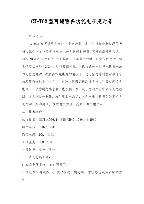
CX-T02型可编程多功能电子定时器一、产品简介:CX-T02型可编程多功能电子定时器,是一个以微电脑处理器为核心配合电子电路等组成的电源开关控制装置。
它可预设定每天或一周内20次不同时间的开/关控制,还具有倒计时、任意循环定时、键盘锁定功能和12/24小时制转换功能,本机内置一枚可充电镍氢电池作为备用电源,在脱离市电电源的情况下,仍可保持计时显示和储存的各项数据达9个月以上。
它采用便携式移动插头形式和微功耗待机电路,可以控制电热水器、电饭煲、饮水机、电动自行车限时充电控制、灯具等各种电器。
您使用本产品后,各种电器将根据您的要求实现自动开启和关闭,既省电又方便,是真正的节电产品。
二、技术参数:执行标准:GB/T14536.1-1998 GB/T14536。
8-1996额定电压:220V~50Hz额定电流:10A(阻性)工作温度:-20~70℃计时误差:≤±1秒/天三、系统功能介绍:1.液晶全屏字符,如右图所示:2.本机在时钟状态下,按“模式”键可将工作状态设定为所需的方式。
设定顺序为:关→自动→开→循环→Zz(倒计时)关—电源输出处于经常关闭状态。
自动—电源输出处于行编定的定时开/关程序状态。
开—电源输出处于经常开启状态。
循环—电源输出按照您设定的开启时间长度和间隔时间长度(关闭时长)来循环工作。
Zz—电源输出处于倒计时(延时关机)状态,最长时间为23小时59分,最短为1分钟。
C—按此键后系统将清除所有储存的数据,系统恢复到初始状态。
四、操作方法在本机进入时钟状态后,可按以下方法进行操作:(一)、校正星期和时间:按“模式”键将定时器工作状态设定为“关”,在此状态下左手按住“时钟”键不放,右手按“日期”键,将星期调整为当前日期,调整好日期(星期)后再按“时”和“分”键将时钟调整为妆前的标准时间。
(二)、设定倒计时(延时关机)时间:按“模式”键将工作状态切换至Zz状态,电源输出即处于开启状态(初始默认时间为8小时),屏幕显示如右图所示:在些状态下按“时”或“分”键修改您所需要本机开启通电的时间,每按一次“时”或“分”键,时间将减少1小时或1分钟,最大时间为23小时或1分钟,最大设定时间为23小时59分,设定完成后按“时钟”键,系统即进行倒计时,此时“Zz”不断闪烁,待时钟退至0:00后,电源即自动关闭。
TP系列可编程定时器使用说明书
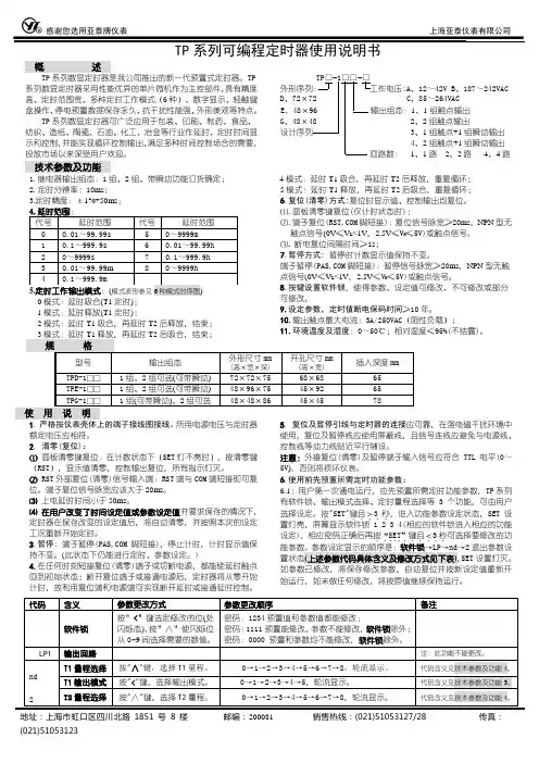
地址:上海市虹口区四川北路1851号8楼 邮编:200081 销售热线:(021)51053127/28 传真:(021)51053123TP 系列可编程定时器使用说明书概 述TP 系列数显定时器是我公司推出的新一代预置式定时器。
TP 系列数显定时器采用性能优异的单片微机作为主控部件,具有精度高、定时范围宽、多种定时工作模式(6种)、数字显示、轻触键盘操作、停电预置数据保存永久、抗干扰性能强、外形美观等特点。
TP 系列数显定时器可广泛应用于包装、印刷、制药、食品、纺织、造纸、陶瓷、石油、化工、冶金等行业作延时、定时时间显示和控制,并能实现循环控制输出,满足多种时间控制场合的需要,投放市场以来深受用户欢迎。
:A 、12~42V B 、187~242VAC D 、72×、85~264VAC E 、48×1、1组触点输出 G 、48×、2组触点输出3、1组触点+1组瞬动输出、2组触点+1组瞬动输出1、1路2、2路 4、4路技术参数及功能1.继电器输出组态:1组、2组、带瞬动功能订货确定;2.定时分辨率:10ms ;3.定时精度:±1%+50ms ; 1模式:延时释放(T1定时);2模式:延时T1吸合,再延时T2后释放,结束; 4模式:延时T1吸合,再延时T2后释放,重复循环;5模式:延时T1释放,再延时T2后吸合,重复循环; 6.复位(清零)方式:复位时显示值、控制输出均复位。
⑴.面板清零键复位(仅计时状态时);⑵.端子复位(RST,COM 脚短接):复位信号脉宽≥20ms ,NPN 型无触点信号(0V ≤V L <1V ,2.5V ≤V H ≤5V)或触点信号。
⑶. 断电复位间隔时间≥1s ;7.暂停方式: 暂停时计数显示值保持不变。
端子暂停(PAS,COM 脚短接):暂停信号脉宽≥20ms ,NPN 型无触点信号(0V ≤V L <1V ,2.5V ≤V H ≤5V)或触点信号。
定时器使用方法

定时器使用方法定时器是一种非常常见的功能,我们可以通过定时器来实现一些定时执行的任务,比如定时发送邮件、定时清理数据等。
在编程中,定时器也是一个非常重要的组件,它可以帮助我们实现一些定时执行的逻辑。
接下来,我将介绍一些定时器的使用方法,希望对大家有所帮助。
首先,我们需要了解定时器的基本原理。
定时器其实就是一个计时器,它可以在设定的时间间隔内执行特定的任务。
在编程中,我们可以通过调用系统提供的定时器接口来创建和启动定时器。
一般来说,定时器的使用可以分为以下几个步骤:1. 创建定时器,首先,我们需要创建一个定时器对象。
在大多数编程语言中,都提供了相应的定时器类或接口,我们可以通过实例化这些类或调用接口来创建定时器对象。
2. 设置定时器的时间间隔,接下来,我们需要设置定时器的时间间隔,即定时器多久执行一次任务。
一般来说,时间间隔可以以毫秒为单位进行设置,比如1000毫秒表示1秒钟。
3. 编写定时器任务,然后,我们需要编写定时器要执行的任务。
这个任务可以是一个函数或一个代码块,定时器会在设定的时间间隔内执行这个任务。
4. 启动定时器,最后,我们需要启动定时器,让它开始按照设定的时间间隔执行任务。
一旦定时器启动,它就会按照设定的时间间隔一直执行任务,直到我们手动停止它。
在实际的编程中,定时器的使用方法可能会有所不同,但基本原理是相似的。
下面,我将以Python语言为例,介绍一下如何使用定时器:```python。
import threading。
def task():print("定时器任务执行")。
# 创建定时器,设置时间间隔为3秒,指定定时器任务为task函数。
timer = threading.Timer(3, task)。
# 启动定时器。
timer.start()。
```。
在这个例子中,我们首先导入了Python的threading模块,然后定义了一个名为task的函数作为定时器的任务。
PTC-15程序可编程定时器说明书

Programmable Timing ControllerThe view mode is used to determine which timer is displayed, or to view (but not change) the set times. To change the timer being viewed during normal running :-1. Press /\ or \/ to show the currently selected timer (T1 at default).2. Press /\ or \/ again to change the selected timer. The timer number (e.g. T3 = T imer 3) will be displayed for 3 seconds and that timer will then be in view. If the timer selected is set to relay mode, the display will show "rly".To view set times:-3. Press SEL. The display will show the timer and set point number (e.g. St21 = timer 2, set time 1) for 3seconds and then shows that set time for a further 3 seconds. If there is a second set time (i.e. in cct and dodo modes) this can be displayed by pressing SEL again.4. Use /\and \/ while viewing the set time to select the timer set point to be displayed.5. The timer will return to normal running after displaying the set time. The last timer to be displayed will now be in view. T o view a different timer while running, repeat steps 1 and 2 above.SELPRGSelects view set time mode. Allows access to set point for adjustment in set mode. Moves adjustment to the next digit in set and program mode. Allows access to parameters for adjustment in program mode.Selects set mode. Selects program mode when held for >4 seconds. Steps through individual timer functions when in program mode. Exits program mode when held for >4 seconds at Mde prompt in program mode.Increments the timer being displayed in view mode. Increments the timer being adjusted in set mode. Increases a single digit in set mode. Steps up through the function menu in program mode.Increases a parameter value or option in program mode.Decrements the timer being displayed in view mode. Decrements the timer being adjusted in time set mode. Decreases a single digit in set mode. Steps up through function menu in program mode. Decreases a parameter value or option in program mode.240 Vac 110 Vac NeutralParameter Function Default Range/Option St11-St51First timing value 90000 to Timing range St12-St52Second timing value 90000 to Timing range PASSPassword to access 00000 = No Password Program 1 - 4999 for adjustable times5000-9999 for locked times 1996 Override PasswordMODE Timing Mode dE dE = Delay On (ndE1-5)Selection int = Interval Timedd = Delay Offcct = Cycling Timerdodo = Delay On Delay Off rLy = Relay Moder nG1Timing Range SECS SECS = 0.1 to 999.9 secs r nG2Selection M-S = 1sec to 99min59secH-M = 1min to 99hrs59minSt Start Mode CtS CtS = Close to StartPtS = Pulse to Start Ptr = Pulse to ResetncYc Cycle Counter 00000000 = Continuous1-9999 cyclestdirCounting Direction uP uP or dn = Up or DownNormal running - viewing time* Input refers to terminals 1 to 5Terminal 1 is input for Timer1Terminal 2 is input for Timer 2 etcNormal running - viewing timer (n)Set mode is used to change the set times.1. Press PRG. The display will show the timer and set point number (e.g. ST21 = timer 2, set time 1).2. Use /\ and \/ to select the timer to be set.3. When the relevant timer is selected, press SEL to allow the set time to be changed.4. Adjust the set time one digit at a time using /\ and \/. Press SEL to move between digits.5. When adjustment is complete, press PRG to store the new setting and move on to the second set time if selected. If a single time mode is in use, the timer will return to run mode.6. Repeat steps 4 and 5 to set the second time.7. Press PRG to return to run mode. The last timer to be set will now be in view. T o view a different timer while running, repeat steps 1 & 2 in view mode above.Program mode is used to set up the operating functions and parameters of the timer. (Refer to the parameter map for programming details)1. Press and hold PRG. The display will show PASS (if a password>0 has been set). Press SEL and use /\ and \/ to enter each digit of the password. Use SEL to move between password digits. When complete press PRG to access the program functions. NOTE : if no password is set (PASS=0000) the display will go directly to the first program parameter (MdE1).2. Use /\ and \/ to move around the program menu (Mde1, Mde2, Mde3, Mde4, Mde5, tdir, P ASS - Mde1, Mde2 … etc.)3. Press SEL to access the program parameter to be changed, use /\ and \/ to change the parameter (using SEL to move between digits where required).4. Press PRG to store the change and move on to the next variable within a particular timer set up ( eg. Mde1, rng1, St, St11 - Mde1, rng1…etc)5. Use /\ and \/ at the Mde prompt to move around the program menu.6. Press and hold PRG at any Mde prompt to exit program mode. The timer active when exiting from program mode will now be in view. T o view a different timer while running, repeat steps 1 & 2 in view mode above.1. Set and program modes will time out if no buttons are pressed for 1 minute. The timer will return to run mode.2. When the program routine has been accessed all timing stops, is reset and all outputs are de-energised.3. Timing continues in set mode. The new set times take effect when the timer is next started.4. The output indicator will light when the relevant output is energised.Panel cut-out 2.755 x 1.77 (70 x 45)All dimensions in inches (mm)。
定时器操作使用说明书

定时器操作使用说明书(总2页)本页仅作为文档封面,使用时可以删除This document is for reference only-rar21 year.March步骤按键按(手动)按(校星期)按(校时)(校分)设左项目使显示器的短横线在自动位巻结束时间设左定时器使用说明书一.功能键说明校星期一一调整星期校时一一调整小时校分一一调整分钟定时一一设置定时开关键时钟一一设置正常时间复位一一清除所有设置取消/恢复一一只起到清除定时设置不动作的功能,指删除1-14组中所设置的任一组(一组包括开和关,例:第二组设置为:U: 02开、11: 03关,如果清除11:02,同时也会将11: 03清除,恢复刚才清除,再按一下清除键即可,恢复后这一组定时会执行动作)自动/手动一一切换接通状态:ON为常开;AUTO为自动;即定时设定起作用;OFF为常关二、定时操作说明鲁复第2-第6步设立第2J6次开关的时间按(时钟)【举例】例如控制器每天下午6点自动打开电源,到夜里2点关闭电源,按以下操作:按一下“定时键”显示器上显示如图1(表示当前定时器没有定时计划)按住“校时”“校分”显示器显示如图2。
再按一下“设时键”显示器显示如图3。
按住“校时”“校分”显示器显示如图4。
以上调整完再按一下“时钟键”注意:定时操作完成后,不要忘记按“自动/手动”键把接通状态设成AUTO状态。
長■白砂黄(图1)(图2〉MO TU IE TH FR SA £U(图3> (图4》。
智能编程定时器操作说明书

文案大全此文档由恒飞电器提供 由杭州寰宇世极功放编写※系统概述:M P 3智能音乐播放器:采用世界最先进的微电脑控制技术。
将广播自动分区播放、外部音频和麦克风录音存储等先进功能综合为一体。
内存大小由你选择: (分别可用U 盘或T F 卡设计),成为广播设备的典范之精品,达到国内领先水平。
广泛适用于校园自动广播音乐打铃、外语广播教学听力考试系统。
※综合功能:M P 3自动广播、智能分区广播、日常教学广播、消防紧急广播、背景音乐播放、外语教学及听力考试广播功能。
※技术参数:信噪比:>90d B ; 谐波失真:<0.1%;频响范围:20H z -18K ; 电压:220V※前面板介绍(由于机型不同布局略有不同)01、电源灯及开关02、插U 盘或连接电脑U S B 囗03、电源灯 (T F 卡插囗)04、显示屏;05、菜单上,下,左,右控制选择键; 06、确定,停止,返回键; 07、咪,输入,监听音量控制键; 08、分区1,2,3,4,5,6按键 09、分区及电源全开全关按键; 10、手动与自动切换按键;重要提示:当你插入新U 盘或TF 卡时,必须先把它插在本机上并开关本机电源,让它自动生成AUDIO 文件夹后并把有编号的MP3歌曲装到AUDIO 文件夹内才可以播放。
※后面板介绍(由于机型不同布局略有不同)2注:短路输入端囗: 当这个端囗有短路信号输入时,本机会立刻播放你放在內存里AL A RM 文件夹内的这一首曲目,AL A RM 这文件夹內只能放一首用于紧急报警用的歌曲,其它需要定时播放的歌曲要放在A U DI O 文件夹內,如歌曲的路径放错则定时播放将不执行。
短路输出端囗: 这个端囗与功放电源和分区的动作同步,即当有定时点到时,这端囗即短路,当定时歌曲放完或设定了结束时间到了即断开,这端囗作用是用于控制电源时序器接多台功放之用。
※设备连接图(由于机型不同布局略有不同)※音乐播放步骤一:按面板上的” 确定” 键,进入主菜单。
CM系列智能式计数器定时器使用说明书
*若以上提供给您的型号仍不能满足您的使用要求,请您与公司总部联系,我们会尽最大的努力满足您的订货。
特点:CM □- P S □ □ AA:进口拨码 B:国产拨码1:表示一段设定 2:表示二段设定显示位数:表示四、五、六位显示S:比率设定P:表示预置外型尺寸:48H*48W、72H*72W 8:48H*96W CM系列仪表型号CM7-PS 61A(CM7-PS 61B )CM7-PS 62A(CM7-PS 62B )CM 8-PS51A(CM7-PS51B )CM 8-PS52A(CM7-PS52B )尺寸(mm)L ED位数段设定继电器输出24V供电供电电源6位单段AL2可订做A C/DC 100~240V A C/DC 100~240V A C/DC 100~240V A C/DC 100~240V6位两段AL1;AL2可订做5位单段AL2可订做5位72H *72W CM 4-PS 41A(CM 4-PS 41B )4位单段AL2可订做A C/DC 100~240V 48H *48W 72H *72W 48H*96W 48H*96W两段AL1;AL2可订做整机功耗<5W供电电源CM4、CM7、CM8:AC/DC 100~240V ±15% 输出类型继电器触点及晶体管同时输出继电器触点容量AC 250V/3A或DC 30V/3A 晶体管输出容量DC 30V/50mA外供电源D C 24V±2V 50mA m ax 绝缘电阻≥100M Ω抗干扰电源:±2kV 输入:±2kV 抗振动10~55H z 0.75mm 参数保存10年环境温度0~50℃环境湿度35~85%R HCM系列智能式计数器/定时器使用说明书◎单排5位或6位LED数码管显示;◎多种封装尺寸可选:48H*48W、72H*72W、48H*96W;◎用拨码及按键设定参数值;◎可逆计数功能,4种输入方式:A、B、C、D;◎两个输出通道(继电器或晶体管):AL1、AL2;12种输出方式:F、N、 R、C、K1、K2、P、Q、A、D、H、L;◎停电记忆功能;◎按键及拨码保护功能;◎按键及外接端子复位功能;◎定时暂停功能;◎8种定时方式,可选十进制或六十进制;◎定时双延时功能,输出延时单位任意选择h(小时)、m(分)、s(秒);一、型号二、技术参数◆计数器参数◆定时器参数输入信号触发沿输入阻抗计数速度计数范围输出延时时间比率设置范围脉冲信号:方波、正弦波;5≤H≤30V 0≤L≤1V 上升沿≥10KΩ5/30/100/1000/3000CPS-1999~9999(4位,最多可保留3位小数显示)-19999~99999(5位,最多可保留4位小数显示)-199999~999999(6位,最多可保留6位小数显示)0.01s~99.99h(4位);0.01s~999.99h(5位);0.01s~9999.99h(6位)0.001~9999(4位);0.0001~999.99(5位);0.00001~9999.99(6位)91+0.54525-0←←←←←←303067.5+0.81467.5+0.8→→→→→→→→CM8CM7CM8注:若仪表有新的改动,恕不再另外通知,请您按实际仪表接线图接线。
SPC-A5定时专用程序控制仪使用说明书
SPC-A5定时专用程序控制仪使用说明书1、可在每天二十四小时中的任意时、分自动开关用电设备或控制响铃。
2、用户可方便地洗、编、检查、修改程序(作息时间表)。
3、编定时间程序后,电脑无需电池可保证停电十年记忆不乱。
4、仪器机内装有可充电电池,在停电五天内,能维持电子钟继续走时(但不显示)。
5、调钟可快进、慢进、倒退。
6、电铃铃声有三种,上课:十短声、下课:一长声:预备:六组两短声。
适用于各机关、团体、学校、企事业单位需要按时间控制用电设备和定时响铃的地方,它具有停电记忆、走时不乱,时间精度高,编程简便等特点。
本SPC系列仪器系国家级新产品,经国家鉴定本系列仪器是目前技术、性能处于国内领先地位的先进产崐品。
本系列产品曾在国际科技与和平周活动中获“中国科技之光进步奖”和“爱迪生”发明金奖。
又被国家贸易部评为质量信得过产品。
天安门广场国旗自动升降及国歌自动播放设备中采用本系列产品。
一、功能和特点:1、可在每天二十四小时中的任意时、分自动开关用电设备或控制响铃。
2、用户可方便地洗、编、检查、修改程序(作息时间表)。
3、编定时间程序后,电脑无需电池可保证停电十年记忆不乱。
4、仪器机内装有可充电电池,在停电五天内,能维持电子钟继续走时(但不显示)。
5、调钟可快进、慢进、倒退。
6、电铃铃声有三种,上课:十短声、下课:一长声:预备:六组两短声。
7、本仪采用发光数码管显示时间,清晰、美观且耐久。
二、技术指标:1、各种动作时间以1分钟为单位。
2、交流电源电压范围:~180V-~240V。
3、平均耗电功率:3W4、各路开关继电器容量~220V,阻性负载10A(2000W)。
5、计时误差≤1秒/天。
6、可编60个时间程序。
7、采用24小时计时制。
8、体积:26×21×11cm3;重量:1.5KG。
仪器使用方法顺序图状态指示灯显示红色:{ ↓按住“模式”(状态选择)键3秒后放掉状态指示灯显绿色:(1)洗掉旧时间程序(2)编制新时间程序(3)检查已编时间程序(4)修改已编程序(如检查无错, 不必进行此项操作)按住“模式”(状态选择)键3秒放掉状态指示灯显红色:校对北京时间具体详见下列使用方法:三、使用方法:(一)开机操作:把仪器插上~220V电源,此时电源指示灯、状态指示灯亮(显红色),显示屏数字不断闪动。
程序可编程定时器单通道PCZ-521.3说明书
PURPOSEOPERATIONProgrammable control timer is used to time control the devices in home orindustrial automation systems by an individual time program set by the user.Timer activates and deactivatesthe device or electrical circuit on theprogrammed hours in cycles: daily, weekly, working days (Mon-Fri) orweekend (Sat, Sun).ON-OFF COMMAND – program entry for enabling or disabling the receiver.500 MEMORY CELLS– internal memory for individual program entries,allowing to program250 pairs of ON-OFF COMMANDS.AUTOMATIC MODEicon on display]MANUAL MODEpermanentlyopen contact (position 1-6) when the AUTOMATIC MODE is off [nodisplay]CYCLE MODE - adjustable, weekly cycle (7 days from Monday to Sunday) ofthe receiver switching in accordance with the programmed ON-OFFCOMMANDS:* single day of the week: Mo; Tu; We; Th; Fr; Sa or Su.* working days: Mo Tu We Th Fr (Monday to Friday).* weekend: Sa Su (Saturday and Sunday)* daily: Mo Tu We Th Fr Sa Su (Monday to Sunday).AUTOMATIC TIME CHANGE - change from winter time to summer time withoptions to change automatically or not. User can set the time zone so that theswitching time is consistent with the local time.PREVIEW DATE- the ability to preview the set date (OK.)PREVIEW OF THE CURRENT PROGRAM – pressing the +/- keys in the datepreview mode displays information about the number and details of thecurrent program.NFC WIRELESS COMMUNICATION- wirelessly read andwrite timerconfiguration from an Android phone equipped with the NFC module.…PCZ KONFIGURATOR” APP - free application for Android mobile phones andtablets equipped with the NFC module for wireless communication.Features:· timer configuration in Offline mode (without the connection with the PCZ-521 timer);· read and write the setup from and to the controller;· quick programming of multiple controllers using a single configuration;· read and write the configuration from and to a file;· sharing the configuration via e-mail, Bluetooth,network drives…· identification of the connected timer and the ability to name individualdevices;· automatic configuration backups. Along with a unique identifier for eachtimer, user can easily restore previous configuration;· set the time and date according to the clock in mobile phone;The app is available on Google Play!CLOCK TIME CORRECTION – set monthly adjustment of the system clock.BATTERY INDICATOR - the controller comes with built-in control system ofthe backup timer battery used in the case of main power supply failure. If thebattery is low, user will receive information that the battery needs to bereplaced. Battery life depends on the ambient temperature and the degreeof the battery wear.OPERATING MODES AND FUNCTIONS3. HOURPress MENU. The clock will enter program menu. Using the +/- buttons selectthe mode for time setting [hour].Clock will show settings for the next parameters: year, month, and day. Usethe +/- keys to set the parameters; move to the next parameter with the OKbutton. Go back to the previous item by pressing MENU.Clock will show settings for the next parameters: hour and minutes. Move tothe next parameter with the OK button. Go back to the previous item bypressing MENU.Press OK to accept date entry. The clock will automatically exit from the datesetting mode and go to the program menu.The date setting is tantamount to time determination: winter or summer.In Poland, the time change from winter to summer is done automatically atnight, on the last Sunday of March at 2.00 AM (by adding 1 hours to thecurrent time). Time change from summer to winter is done automatically atnight, on the last Sunday of October at 3.00 AM (by subtracting one hourfrom the current time).NOTE!The automatic time change can be turned off (see section 8.1).Press OK to accept time entry. The clock will automatically exit from the datesetting mode and go to the program menu.4. ON-OFF COMMAND - setting the parametersPress OK to accept (or select another number using the +/- keys). Clock willenter the single ON-OFF COMMAND parameters setting mode.A. Operation cycleB. Hour and minutesClock will show setting for the next parameters: hour and minutes.Set the values using +/- keys; move to the next parameter with the OKbutton. Go back to the previous item by pressing MENU.Press MENU. The clock will enter the program menu. Using the +/- buttonsselect the mode for time setting [prog].Press OK to accept. The clock will enter the memory cell number selectingmode. The display will automatically show the number of the first emptymemory cell.DISPLAY AND CONTROL PANEL DESCRIPTIONMo – Monday; Tu – Tuesday; We – Wednesday; Th – Thursday; Fr – Friday;Sa – Saturday; Su – Sunday.DATE AND TIME/PROGRAM ENTRIESDAYS OF WEEK/WORK CYCLEUSER CONTROL FUNCTION SUMMARYMENU:- enter the program menu- return to the previous position (back).OK:- move to the next setting- accept setting- preview of the date and the current program+ [Plus]:- change the setting by one position up for the selected programming option(holding down the button continuously changes the setting by one positionup in a loop)- in MANUAL MODE: permanent ON and OFF contact switching- [Minus]:- change in the setting by one position down for the selected programmingoption (holding down the button continuously changes the setting by oneposition down in a loop)- in MANUAL MODE: permanent ON and OFF contact switching1. START1.1 Connect the power supply.1.2 The clock will start at the root level and the display will show set hour.In the absence of any program entries timer will automatically run in manualmode. If the previous entries are present, timer will execute the program. Toerase all previous settings, see section 8.6.1.3 Set individual timer program with internal configuration menu or usingthe "PCZ Konfigurator" app for mobile devices.PROGRAMMING2. DATEPress MENU. The clock will enter program menu. Using the +/- buttons selectthe mode for date setting [date]Confirm with OK.LCD BRIGHTNESS ADJUSTMENT - change the contrast of the display to get aclear LCD read-out in different viewing angles.RELAY STATE MEMORY - the relay state in manual mode will be rememberedeven after power supply failure.-1--2-OFF2OFF2* Switch-on time of contact established by a pair of ON-OFF commands canbe longer than 24 hours, which means that [ON] command can be set to anytime and any day of the week (e.g. Tuesday, 1:45 PM) and [OFF] command toany hour of another day of the week (e.g. Thursday, 5.05 PM).5. EDITION OF ON / OFF COMMANDS PARAMETERSB. ON / OFFClock will allow to choose [ON] or [OFF] option.Set ON or OFF using +/- keys; confirm with OK. Clock will automatically enterthe next ON-OFF COMMAND parameter input mode.NOTE!* The entered ON-OFF commands do not constitute solid pairs of commandsfor switching on and switching off a contact. They are treated as individualcommands and executed in accordance with the specified time chronology.Cases of overlapping contact closing times from two pairs of ON-OFFcommands are illustrated in the following diagrams:2Press MENU. The clock will enter the program menu. Using the +/- keys selectthe parameter edit mode [edit]Press OK to accept. The clock will enter the memory cell number selectingSet OPERATION CYCLE using +/- keys:* single day of the week: Mo; Tu; We; Th; Fr; Sa or Su.* working days: Mo Tu We Th Fr (Monday to Friday).* weekend: Sa Su (Saturday and Sunday)* daily: Mo Tu We Th Fr Sa Su (Monday to Sunday)Press OK to accept.-3-Proceed as with ON-OFF COMMAND parameters setting (see section 4).-4-Continued on page 56. CLEARING A PROGRAM – removing entriesConfirm by pressing OK. The cell will be deleted. The clock will display the next programmed cell number.Pressing MENU will take you to the root level.NOTE! To erase all previous ON-OFF COMMANDS settings see section 8.6.Accept by pressing OK. The clock will enter work mode menu (auto – hand). With +/- keys select desired operation mode:7. OPERATION MODEPress MENU. The clock will enter the program menu. Using the +/- keys select [mode ].*MANUAL – “hand”*AUTOMATIC – “auto”Accept by pressing OK. The clock will automatically exit the operation mode selection and go to the program menu. Pressing Menu one more time will take the clock back to the root menu.NOTE! To change the contact position in the MANUAL OPERATION mode use the +/- keys at the root level.In the absence of any program entries timer will automatically run in MANUAL MODE (there is no option to set AUTOMATIC OPERATION MODE).Confirm by pressing OK. The clock will enter the System Settings submenu (dst - utc -batt - cal - LCD - clear - info). Select the parameter and confirm with OK. Pressing MENU will take you to the upper level.8. SYSTEM SETTINGSPress MENU. The clock will enter the program menu. Using the +/- keys select system settings [syst].pressing OK. The clock will enter the menu with the option to disable automatic time change (auto-off). With +/- keys select desired mode:*with AUTOMATIC TIME CHANGE – “auto ”*without AUTOMATIC TIME CHANGE – “off”Press MENU. The clock will enter the program menu. Using the +/- keys select ON-OFF COMMANDS reset mode [del].Press OK to accept. The clock will enter the memory cell number selecting mode. Select the cell to be deleted and accept by pressing OK. The clock will be waiting for confirmation of deletion. This is indicated by alternatingflashing of the number of the selected cell and its set parameters.Continued from page 48.2 Time zone – utczone (12/-12). Pressing +/- keys set time zone for the clock. Confirm bypressing OK. Time zone for Poland is +1.8.3 Battery charge indicator – battConfirm by pressing OK. The clock will display information about batterycharge level.HIGH - (100%)GOOD - (80%)LOW - (15%)EMPTY - (0%)8.4 System clock time adjustment - calTime adjustment is thenumber of seconds by which the system clock is adjusted per month. Setting range: +/- 300 seconds.For example: If the clock is fast 4 seconds per month, set the parameter value -4.Confirm by pressing OK. The clock will display current parameter of time adjustment. Press +/- keys to set desired number of seconds. Confirm bypressing OK.8.5 Display contrast - lcdSetting the display contrast. Range: -3 (lowest) ... + 3 (highest).Confirm by pressing OK. The clock will display thecurrent contrast parameter. Use the +/- keys to set the contrast parameter. Confirm bypressing OK.8.6 Resetting the commands, parameter settings and errors - clearUse the +/- keys to select reset option.Use the +/- keys to select reset option:* [prog ] - deleting ON/OFF entries * [sys ] - resetting the system settings Confirm by pressing OK.A. progConfirm selected option by pressing OK. The clock will enter standby mode awaiting for deletion confirmation. This is indicated by alternating flashingof "prog" and "clear" on display.Confirm by pressing OK. The clock will start deleting entries. The display will count off consecutive numbers of deleted entries (from 1 to 500). Upon completion the display will show [prog].B. sysConfirm selected option by pressing OK. The clock will enter standby mode awaiting for deletion confirmation. This is indicated by alternating flashing of [sysr ] and [clear] on display.count off consecutive numbers of deleted entries (from 1 to 500). Upon completion the display will show [sys].C. errorIf the timer system detects an error, the display will show "error" message at the root level. At the same time in the "clear" section the extra "error" item will appear. Error reset is possible only through the menu (menu -> syst -> clear -> error).Confirm the “error” option by pressing OK. The clock will enter standby mode awaiting for deletion confirmation. This is indicated by alternating flashing of"error" and "clear" on display.“error”. The clock will return to standard operation mode.Confirm by pressing OK. The clock will enter the information menu. Browse the information by pressing +/- keys:*clock type-8-IN/OUT DESCRIPTION3-4 timer power supply 1 COM contact input 5 NO contact output- “standard open” position 6 NC contact output- “standard closed” position156CONNECTION SCHEMEINSTALLATION1 Turn off the power.2. Mount the timer on the TH rail in the distribution box.3. Connect wires according to the diagram.4. Connect receivers according to the diagram.5. Set the correct date (see section 2) and time (see section 3).6. Set individual time program for receiver switching on.TECHNICAL DATApower input 24÷264V AC/DCcurrent load <16Acontactseparated 1NO/NCup time of the clock (for T=20°C) 6 years battery type2032 (lithium)up time of the display operation no informationthe accuracy of the clock 1s time error±1s/24h precision of program time setting 1min.program memory cells 500(250 pairs ON/OFF COMMANDS)power consumption 1.5W operating temperature -20÷50°Cterminal2.5mm screw terminalstightening torque 0.4Nmdimensions 2 modules (35mm)mountingon TH-35 railprotection gradeIP20L NBATTERY REPLACEMENTUser can single-handedly replace the battery.Detailed instructions with pictures and videos can be found on the website .pl on thesubpage of the timer. Battery type: 2032 (lithium).-6--5--7-D151109P r o g r a m m i n g s c h e m e8Adding and editing programsžAdd or edit program displays a windowwith following options:ž Operation – selects whether theprogram will turn the relay on or off .ž Day – selects the days of programexecution. You can select a single day, Monday - Friday, Saturday - Sunday, all week.ž Time – selects the time of program execution.Main window1) New configuration – opens window for creation of a new controller configuration.2) Open configuration- opens window for loading the program configuration stored as a file in the phone memory. 3) My device - gives access and support for all backup copies of configurations assigned to specific devices.4) Information – application user guideNew configuration1)N e w – c re a te s n e w, e m p t y configuration file (without any programs).2) Load from PC – new configuration is created based on a program saved in the PCZ controller.Select this option and bring the phone closer to the timer to load the program from the phone to the application. 3) Load from file - new configuration is created based on a files saved by the user. Opens a window with a list of files previously saved by the user.4) Restore - a new configuration is created based on a backup copy of one of the previous configuration. Tapping this icon opens window with a list of backups split into controllers in which they were written. Select a new configuration option opens another window.The function window allows to edit program as well as to load and save configuration to a PCZ controller. It appears automatically when we bring the phone closer to the controller, or when we create a new configuration. In the upper part of the screen the application displays a frame with following information:Dev – supported controller type ID – unique identifier of connected controller (appears only when the application is connected with the controller. In the Offline mode that field remains empty). Icon of a pencil on the right-hand side allows you to enter your own name for the controller.Operating mode – displays the current operating mode for the controller (manual or automatic). Applies only to operating in Online Out mode – Output relay status (enabled or disabled). Applies only in Online mode. Keys:1) Read the timer configuration.2) Save the current configuration to the timer.3) Load configuration from file.4) Save the current configuration to file. 5) Restore configuration from backup copies.6) Edit the current configuration.EditEditing window allows you to edit current configuration (new, loaded from file or from PCZ)Editing window consists of three tabs: 1) List - a list of all programs (in the order in which they are stored in the memory).2) Filter - a list of programs that will be executed on the selected day (in chronological order by program execution).3) Settings – system settings configuration.ListMain part of the screen is taken by the list of PCZ programs. Programs are displayed sorted by the time they are written in the controller memory.Each program is symbolized by: ž action icon - the green "v" means that the specific program will activate relay. Red “x” means deactivation of relay.ž Date and time – show days of programs activation and their start time.ž Program number - program position in the controller memory. Bold font marking represents a program that is (or should be) executed. Pressing the trash bin icon next to the program entry deletes program. To add a new program select "Add Program". To edit an existing program tap into the edited program.The three icons at the bottom of the screen allow you to:ž Save to file - saves the current configuration to a file.ž Save to PCZ - saves the configuration to a timer.ž Back - returns to the function window.Upon returning to the function window, current configuration is stored in application memory.FilterFilter tab performs a similar function to List. In this case, at the top of the screen appears addition frame for choosing the day and time interval for which the application displays a list of programs active during that time. Programs are displayed in chronological order, sortedby the time of their actual execution.Configurator AppPCZ https:///store/apps/details?id=.fif.clockprogramer。
控制器的定时功能说明书
控制器的定时功能说明书一、简介控制器是一种智能化设备,具备定时功能,本说明书旨在向用户介绍控制器的定时功能以及如何操作。
二、定时功能概述控制器的定时功能可以让用户按照自己的需求,在设定的时间范围内自动启动或关闭设备。
用户可以通过控制器上的面板或者手机应用进行设置。
三、设置定时1. 打开控制器电源,确保控制器正常运行。
2. 进入定时功能设置页面,可以通过面板上的按键或者手机应用进行设置。
3. 根据实际需求,选择启动时间和关闭时间,以及重复周期(一次性、每天、工作日等)。
4. 确定设置后,保存并退出设置页面。
四、定时功能示例假设用户需要每天早上7点自动启动设备,在下午6点自动关闭设备,可以按照以下步骤进行设置。
1. 进入定时功能设置页面。
2. 选择每天作为重复周期。
3. 选择7点作为启动时间。
4. 选择下午6点作为关闭时间。
5. 确认设置后,保存并退出设置页面。
五、特殊定时功能说明1. 周期定时:用户可以根据需要设置周期性的定时,例如每周一、每个月第一天等。
2. 延时定时:用户可以设置设备在一定时间后启动或关闭,例如定时1小时后关闭等。
3. 多时段定时:用户可以根据实际需求设置多个定时段,使设备在不同时间段内开启或关闭。
六、注意事项1. 定时功能需要确保控制器处于正常工作状态,请及时检查电源是否连接稳定。
2. 在设置定时功能前,请确认设备是否处于关闭状态,否则定时功能可能无法正常启动。
3. 如需修改定时设置,请进入定时功能设置页面进行修改,并确保保存修改后的设置。
4. 定时功能仅针对控制器连接的设备生效,请确保设备已连接到控制器并正常运行。
七、总结控制器的定时功能使用户能够更加智能、便捷地控制设备的启动和关闭,同时也提高了设备的能源利用效率。
通过本说明书,您已了解了定时功能的基本操作及注意事项,希望能够帮助到您使用控制器的定时功能。
如有任何问题或需要进一步的帮助,请随时联系我们的客服。