LANDesk产品手册2010上海联阳
高德瑞克公司产品用户手册说明书
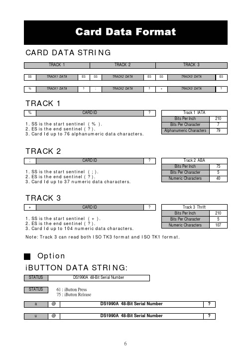
CARD DATA STRINGTRACK 11. SS is the start sentinel ( % ).2. ES is the end sentinel ( ? ).3. Card Id up to 76 alphanumeric data characters.TRACK 21. SS is the start sentinel ( ; ).2. ES is the end sentinel ( ? ).3. Card Id up to 37 numeric data characters.TRACK 31. SS is the start sentinel ( + ).2. ES is the end sentinel ( ? ).3. Card Id up to 104 numeric data characters.Note: Track 3 can read both ISO TK3 format and ISO TK1 format.iBUTTON DATA STRING:OptionSTEP 1 : Run MSR ConfigureSTEP 2 : Choose PS/2 or COM port and press “Scan” ,connect theMSR220/250 reader.START MSRCONFIGURE SOFTWAREApply the bundled disk no. 5296 to begin with the demo software.STEP3 : Click “Read” ,scan the MSR220/250 reader parameter.General :Interface : MSR Interface is being detected. Buzzer : Choose buzzer enable or disable.Feed Back : Set MSR output data ,waiting for feedback from the terminal. Show `Error 'message if no reaction from MSRRS232(UART): Setting MSR communication parameter ,when RS232 and serial USB enable .Package :Setting MSR & iButton data output package .MSR Data Package :iButton Data Package :Data Format :Keyboard : Setting MSR language ,when keybpard enable .FE1 : Package ending character.FS :Package leading character.FE0 : Package ending character.check : Bit check up.iButton: Set iButton data format .Data format :Present ID format : Set present iButton output ID format .Release ID format : Set release iButton output ID format .Family Code : Terms for iButton series.PS : iButton present prompt character.RS : iButton Release prompt character.SS : Start Sentinel ES : End SentinelFF : To set up direct side cardswipe prompt character.RR : To set up reverse side cardswipe prompt character.Swipe Card Direction : To set up prompt character for direct/reverse side card swipe prompt character.Decode Standard : To decode magstripe format.Mark Code :Leading character to set up output data.Decode Mode : To decode magstripe data.Magnetic Card: Set MSR data format and data output parameter .SS : Start Sentinel ES : End SentinelTK ES0 :Ending prompt character .TK ES1 : Ending prompt character .Track Output Order : To set up track data in turn.Track Length : To set up track data length.Head Compatible : To set up the decoding work for IBM or JIS2 data output at one time only.MSR package :JIS2 :JIS2 data format.AAMVA :AAMVA data format .IBM :IBM data format .7Bit : 7 Bits Per Character data.ABA :5 Bits Per Character data .STEP4 : Click “Write” ,write the parameter to MSR220/250 reader .Click “Open or Save” open or save your choose parameter to file. PS.Same as to when MSR220/250 reader is in RS232 interface mode,Keyboard function will be in disable mode .When MSR220/250 reader is in Keyboard function, RS232 interface will be in disable mode.STEP5 : Click “Test Mode” can test the MSR220/250 .STEP6 : Click “Default” can reset MSR220/250 parameter.。
上海南浦仪表厂导线式热电偶产品资料选型手册说明书

上海南浦仪表厂产品资料选型手册 导线式热电偶是近几年从国外引进的一种高效的测温体,导线热电偶柔软,可以任意弯曲抗震,操作方便,热响应时间快,温度准确。
上海南浦仪表厂产品资料选型手册 导线式热电偶是近几年从国外引进的一种高效的测温体,导线热电偶柔软,可以任意弯曲ຫໍສະໝຸດ 震,操作方便,热响应时间快,温度准确。
上海南浦仪表厂产品资料选型手册 导线式热电偶是近几年从国外引进的一种高效的测温体,导线热电偶柔软,可以任意弯曲抗震,操作方便,热响应时间快,温度准确。
上海南浦仪表厂产品资料选型手册 导线式热电偶是近几年从国外引进的一种高效的测温体,导线热电偶柔软,可以任意弯曲抗震,操作方便,热响应时间快,温度准确。
斯皮克拓扑撒布器产品说明书

1008146 Rev. A©2010 Spyker Spreaders/A Brinly-Hardy Co.Model P30/S30 SeriesSpyker SpreadersContact Us at 800.972.6130This manual contains information for the safetyof persons and property. Read it carefully before assembly and operation of the equipment!IMPORTANT Operator's Manual1008146 Rev. A2Spinner/Axle Explosion1008146 Rev. A3No.Part Number Qty Description105-94-00646Nylon Washer2SS-91-0004131/4-20 Nylon Locknut,SS31007745-011Towtube, Polished1007744-101Towtube, Painted 41007746-011Control Handle, Polished 1007740-101Control Handle, Painted 510078282Handle Knob61008023-011Frame, Polished1008026-101Frame, Painted705-90-0080111/4-20 x 1-3/4" HexBolt SS8SS-94-00071Hopper Bottom Bearing 905-44-22101Accuway Screw Assembly 1005-71-22051Hopper Bottom Plate 1105-94-00422Rate Gate/AccuwayGuide1205-94-00431Accuway Diffuser1399-10-020551/4-20 x 1/2" Bolt, SS 1405-94-00681Rate Gate1505-94-00691Dial Mount16SS-94-00061Plastic Dial1705-94-00781Pine Tree Clip1805-24-11021Rate Gate Link, Polished 1910081281Hopper, 12520 Series 10081321Hopper, 17520 Series 2005-93-00751Spyker Accuway Label 2110080671Spyker Decal 2210081651Flow Control Decal23SS-90-00021Roll Pin 1/8 x 7/8"24SS-92-00022Felt Washer2505-125-00701Spinner Shaft26SS-90-00011Roll Pin 1/8 x 3/4" 2705-90-009325/8" Gearbox Bushing 2805-90-009423/8" Spinner ShaftBushing2905-90-009613/16 x 1" Dowel Pin, SS 3005-94-00331Bevel Gear3105-94-00341Pinion Gear No.Part Number Qty Description3205-288-10271Nylon Pin Retainer3305-90-00978#10-24 x 5/8" FlangeHead Bolt, SS3405-91-00088#10-24 Nylon Locknut,SS3505-94-00371Gear Box Cover Front 3605-94-00381Gear Box Cover Rear 3705-98-01111Grease Zerk 3810081251Axle3905-95-0016-JD2Wheel40SS-94-0012-11Spinner4110081041Screen42SS-96-00031Agitator Wire4305-179-0040 2Tow Bar Brace, SS 1000566-102Tow Bar Brace, Painted 4405-90-003811/4-20 x 2" Hex Bolt, SS 4505-90-006513/16 x 1-3/4" Clevis Pin 4605-90-00891Hairpin Cotter, Large 4705-92-00041Wheel Washer, SS 481001693-012Hitch Plate, Polished 1001147-102Hitch Plate, Painted49SS-90-00061Clevis Pin5005-92-00141Nylon Spacer5105-90-00401Rue Ring Locking Pin 521007739-011Control Bracket, Polished 1007709-101Control Bracket, Painted 5310077421Control Link54SS-90-001111/4-20 x 1-1/4" HexBolt, SS5545M0909SS10Washer, SS5645M2121P45/8" Flat Washer57B-6978-012Spacer58D-146P1Hairpin Cotter, Small59F-2832Axle Bearing60F-5751Special Thick Washer 6110081461Operation Manual1008146 Rev. A41. Install spinner to spinner shaft. Press down onspinner until it snaps into place on the roll pin,Figure 1.2. Install axle/transmission assembly into frameas shown, Figure 1. IMPORTANT! Note theorientation of the axle/transmission assembly is critical. See the hole locations in Figure 1. One side has hole near the end of the axle, the other next to the frame.3. Slide the axle bearings over the axle andinto place in the frame, Figure 1.4. Install a 5/8" metal washer, axle spacer, and asecond 5/8" metal washer onto axle, Figure 2.Slide wheel onto axle. Repeat on other side.5. On the drive side of the axle, insert the small clevispin through the holes in the wheel and axle, Figure3. Install Small Cotter Pin.Axle Bearing1008146 Rev. A 51008146 Rev. A66.On the other side of the axle install a wheel washer and rue ring locking pin, Figure 4.7.Place hopper onto frame. IMPORTANT! Note orientation of rate dial. Be sure to slide spinner shaft into hopper , Figure 5.8.Insert 1/4" Nylon Washer onto 1/4-20 x 1-3/4" Bolt. Insert through hopper and frame. Attach finger tight only with 1/4" Nylon Insert Locknut, Figure 5. Repeat for remaining 3 bolts, washers,and nuts. Tighten fully.9.Slide felt washer over spinner shaft, Figure 6. Insert Agitator wire by sliding through the hole in the spinner shaft as shown. IMPORTANT: Note orientation of agitator wire when installing.Figure 61008146 Rev. A710. Install Hitch Tow Bar onto frame, Figure 7. Attachwith 1/4-20 x 1-3/4" Bolt and 1/4" Nylon Insert Locknut.11. Install Hitch Plates to end of Tow Bar using 1/4-20x 1-3/4" Bolts and 1/4" Nylon Insert Locknuts, Figure 8. Install Hitch Pin and Large Cotter Pin, Figure 8.12. Slide Control Lever into U shaped bracket asshown, Figure 9. The label on the U shaped bracket faces the hopper .13. Install Control Linkage into Control Lever . NOTEorientation of on-off label on U shaped bracket. The shorter section of linkage should face upward and away from lever as shown, Figure 9.Longer Section of LinkageShorter Section of LinkageLabel14. Install 1/4-20 x 1-1/4" Bolt and 1/4" Washerthrough the U shaped bracket, Figure 10.15. From inside the bracket install Nylon Spacer , ThickNylon Washer then through Control Lever. Install second 1/4" Washer and 1/4" Nylon Insert Locknut. Tighten.SpacerThick Nylon Washer 1/4” Washer1/4” Nylon Insert Locknut 1/4-20 x 1-1/4” Bolt1/4” WasherFigure 9Figure 1016. Turn Control Bracket assembly sideways as shown,Figure 11. Install end of linkage into rate gatebracket.17. Install front of control lever assembly onto Tow Barwith 1/4-20 x 1-3/4" Bolt, 1/4" Washer (oneon each side of tow bar) and 1/4" Nylon InsertLocknut, Figure 12. Do not fully tighten at thispoint.1008146 Rev. A818. Install Frame Braces to Frame using 1/4-20 x1-3/4" Bolt, 1/4" Washer (one on each side) and1/4" Nylon Insert Locknut, Figure 13.19. Attach Frame Braces to Tow Tube/Control LeverAssembly using 1/4-20 x 2" Bolt, 1/4" Washers(one on each side), and 1/4" Nylon Insert Locknut.20. With rate gate dial set to 0, move control leverback and forth and ensure rate gate opens andcloses fully, Figure 14. If necessary adjust ControlLever Bracket assembly forward or necessary. Fully tighten hardware from steps 17 and 19 that holdControl Lever Bracket in place.21.Install Screen into Spreader.Rate GateFigure 141008146 Rev. A9READ BEFORE USING OPERATE SAFEL YKeep bystanders away when you operate this machine. Use this machine for intended purpose only.Do not let children or an untrained person operate machine.Keep all parts in good condition and properly installed. Fix damaged parts immediately. Replace worn or broken parts.Do not modify the machine or safety devices. Unauthorized modifications to the machine may impair its function and safety, and void the warranty.Do not let anyone sit or ride on equipment during operation. Keep riders off attachment.Wear substantial footwear and long trousers. Do not operate the equipment when barefoot or wearing open sandals.Do not wear loose fitting clothing that can get caught in moving parts.Always wear eye protection when operating the equipment.Stay alert for holes in the terrain and other hidden hazards.Watch out for traffic when crossing or near roadways. Before you operate any feature of this machine, observe your surroundings and look for bystanders.Always wash hands after contact with fertilizers and pesticides.Keep all nuts, bolts and screws tight to be sure the equipment is in safe working condition.1008146 Rev. A10Become Familiar With The Operation Of The Spreader BeforeYou Put Material In The Hopper• Practice walking with the spreader, opening and closing the rate gate at the appropriate times.• Travel at a constant speed and operate the spreader lever position. Remember: Open the rate gate after the spreader is in motion at operating speed (about3 mph, or at a brisk walking pace).• Close the rate gate while spreader is still at operational speed.Dial Setting InformationThe RATE DIAL has 9 numbers with 10 stops between each number. This allows for accurate control of the spreading rate. The dial is set with only a turn, it will automatically lock into the set position. LINE UP THE DIAL NUMBER WITH THE DIAL INDICATOR.• The spread width ranges from 4 - 12 ft. wide depending on the volume/density, particle size of the material, and rate of travel.• The spread thins or feathers at the outer edges, eliminating sharp, "Edge Of Spread" lines whichcause stripes and streaks. Extra coverage can begiven under trees and other heavy feeding areaswithout showing "Edge Of Spread" lines.• Gaps and double overlaps are less likely. Small errors in travel are forgiven and do not show.WARNING: When spreading products containing herbicides, exercise extreme caution with respect to careless spreading and to wind-drift.Contact Of Some Products On Some Plants Can Be FatalIf a dial setting is not found, use the size and weight comparison table found in this manual. Determine a dial setting on the low side. If the setting proves tobe too low, cover the area more than one time. A higher setting can be used when a proven dial setting is established.Remember: Published dial settings are approximate only. The operation of the spreader, the condition of the material (damp or dry or over-pulverized) and weather conditions, are all contributing factors.For these reasons, it is often a good idea to spread the area 2 times - or one-half rate - in cross directions (SEE INFORMATION ON ONE-HALF RATE DIAL SETTINGS). One-half rate dial settings are highly recommended under damp and humid conditions.Rotary AgitatorUse the rotary agitator only if needed. Free-flowing, lump-free materials will not require the agitator. The rotary agitator is easily installed or removed. Note the clockwise rotation and sweep. Place felt washer aroundspinner shaft before inserting agitator.Now You Are Ready To Put Material In The Hopper WARNING: Avoid Injury! Chemicals can be dangerous. Avoid injury to operators or bystanders.• Make sure the rate gate is in the closed position.• Read chemical container label for handlinginstructions. A Material Safety Data Sheet (MSDS)should be supplied by the chemical dealer andprovides proper safety information.1008146 Rev. A11• Wear proper clothing and safety equipment while handling or applying chemicals.• Prohibit all smoking, drinking, and eating around chemicals.• When spreading products containing herbicides, exercise extreme caution with respect to carelessspreading and to wind-drift. Contact Of SomeProducts On Some Plants Can Be Fatal.• Fill the spreader on a flat, level surface only. Fill on sidewalk, driveway, cardboard, etc. to avoid material loss.• When filling hopper with material, always use screen to help break up clumps.Now You Are Ready To Spread• Keep spinner blade clean. Excess material build-up can cause an uneven spread pattern.• Keep the impeller level when spreading.• DO NOT overload. Maximum capacity of 12520 Series is 125 lbs. Maximum capacity of 17520Series is 175 lbs.• DO NOT use on windy days.• Spread header strips at the ends of the area OPPOSITE of the direction of spreading. This willprovide a "turn-around" area, an area to re-align the spreader for the return spread.• Example shown is for 6 ft. wide spread. Make the first spread pass at one-half the spread width from the edge of the spreading area or in this case,approximately 3 feet (or one big step).• Additional spreading passes will be at the full spread width or approximately 6 ft. apart.• TAKE A SIGHTING AT THE FAR END. Keep your eye on the sighting as you spread. You will not needto wonder where you are or where you have been.Continue until spreading is completed.• Left over fertilizer can be spread under trees and other high feeding areas without showing "edge ofspread" lines.Cleaning The Spreader Is Part Of The Spreading JobClean and oil spreader immediately after each use. Method #1 - Wipe spreader thoroughly with an oily cloth. Oil all bearings and bearing areas.Method #2 - Wash, rinse, and dry the spreader. Note: Drying takes time. Moisture trapped in bearing areas is slow to go. Immediately after drying - oil all bearings and moving parts. Make certain all operations are thorough. NOTE: Good "Dry Cleaning" is preferable to poor "Wet Cleaning".• It is virtually impossible to have rust and corrosion ona clean, dry, oiled surface.• Again - just before using - oil all bearings and moving parts.• In storage, ideally the spreader should be hung by the handle. In any case, do not pile weight on thespreader, as excess weight over a period of time can distort the tires.Oil Bearings And All Moving PartsMake sure the spreader is running freely!1008146 Rev. A12ACCUWA Y - What It DoesThe Accuway Spread Pattern Equalizer Balances the spread pattern - Bulls Eye - Dead to the Center of the Spreader.All products. All spreading conditions.Skewing is eliminated. Does not change the spread width.ACCUWA Y - How It WorksAccuway shifts the material placement on the spreader spinner fan. This in turn, balances the pattern heavier to the right or heavier to the left.Spread pattern can be affected by many variables such as humidity, temperature, wind, spreader condition, speed of travel, material size and weight. Because of these variables, the diffuser must be adjusted for each type of application. Proper adjustment will minimize skewing and uneven coverage.Adjustment is very sensitive. Turning the Accuway Diffuser Knob just a little will result in a drastic change to the spread pattern.The Accuway Diffuser Plate has a front and a rear ramp. Never adjust so that the diffuser plate splits the material flow to both the front and rear ramp at the same time.If the spreader is spreading to the left of center, turn the diffuser knob counterclockwise fully. Then adjust clockwise until the edge of the diffuser plate centers the spread.If the spreader is spreading to the right of center, turn the diffuser knob clockwise fully. Adjust counterclockwise until the edge of the diffuse plate centers the spread. NEVER USE ACCUWAY FRONT AND REAR RAMPS TO SPLIT THE PRODUCT FLOW. Use only the front side or the back side. With proper adjustment you should beable to achieve a balanced spread pattern.1008146 Rev. A131008146 Rev. A14Spreader does not sit flat The "feet" or the flattenedportion of the spreader hoppersupport tubes are not benting a hammer or pliers, bend the feet to be equal with each other.Deflector shut off is binding and will not open/close properlyShut off plate is jammed withdebris.Thoroughly wash out hopperand shut off plates with water.Ensure debris is not stuckbetween shut off plate andrate gate plate. TROUBLESHOOTING1008146 Rev. A 151008146 Rev. A。
朗克(Parker)橡胶管袋和支架系列产品说明说明书
B r a s s V a l v e s : V i s u a l I n d e xTable of ContentsVisual Index ............................................................................................................................H2Ball Valves ..............................................................................................................................H6 Wide range of brass, carbon steel and stainless steel ball valves. For use as fuel shut-off lines and other general purpose applications that require shut-off capability.Note: Please refer to Catalog 3501-E for special working pressures and other technical data.Drain Cocks ..........................................................................................................................H11 System temperature and the type of tubing should be considered. Ground plug shutoffs are designed to withstand 30 psi working pressure. Drain cocks are designed to withstand up to 150 psi working pressure, unless otherwise noted.Needle Valves .......................................................................................................................H12 Up to 150 psi working pressure, unless otherwise noted.Truck Valves ..........................................................................................................................H14 Up to 150 psi working pressure, unless otherwise noted.“How to Order” Information .....................................................................................................18Chemical Compatibility Guide..................................................................O10, Visual IndexIndustrial ValvesXV500PFemale-Female page H6XV500HP-XFemale-Female (Large)page H6XV502PPanel Mount page H7XV520PEconomy Series page H9XV533P3 Way Diversionpage H9XV540P4 Waypage H9XV600P6 Port Diversionpage H9XV633P6 Port Diversion page H9XV500CSCarbon Steelpage H6XV502CSPanel Mount Carbon Steel page H7XV502SSPanel Mount Stainlesspage H8MV709Micro Valvepage H6MV609Mini Valvepage H6XV501P Male-Female page H7XV590P90° Valve page H9XV590P-X-0490° Valve page H9XV501SSStainless Steelpage H7MV708Micro Valvepage H6MV608Mini Valve page H6XV509PSolder - Solder page H8Female PortsMale- Female PortsSolder PortsB r a s s V a l v e s : V i s u a l I n d e xIndustrial Valves (Continued)XV591P90° Valve page H9XV591P-X-0490° Valve page H9XV506P Female - Female page H8XV506PFemale - Female (Large)page H8XV510PMale - Female page H8XV506CSCarbon Steel page H8XV506HP Straight Thread page H8XV506HP-XStraight Thread (Large)page H8XV500HP-XFemale Portspage H6XV500HP-XFemale Ports (Large)page H6XVP500HP-X Female Ports-Padlockingpage H9XVP500HP-XFemale Ports-Padlocking (Large)page H10XVP500PFemale Ports page H10XVP501PMale - Female page H10XVP502PPanel Mount page H10XVP510PStraight Thread page H10XVP500CSCarbon Steel page H9XVP502CSPanel Mountpage H10XVP502SSStainless Steel page H10XVP506HP-XStraight Thread page H10XVP506HP-XStraight Thread (Large)page H10XVV500PFemale Ports page H10XVV501PMale-Female page H11XVV502PPanel Mount page H11XVVP500PFemale Ports page H11XVVP501PMale-Female page H11XVVP502PPanel Mount page H11XV500P-X-04Female Ports page H6XV501P-X-04Male - Female page H7XV502P-X-04Panel Mount page H7XV510P-X-04Straight Thread page H9XV500CS-X-04Carbon Steelpage H6XV500P-X-21Female Ports page H6XV500P-X-21Female Ports page H6XV502P-X-21Panel Mountpage H7Male-Male PortsStraight Thread PortsStraight ThreadPorts-High PressureFemale Ports-High PressureFemale Ports-Padlocking- High PressurePadlockingVentedStraight Thread Ports-Padlocking-High PressureVented-PadlockingTee HandleOval HandleB r a s s V a l v e s : V i s u a l I n d e xIndustrial Valves (Continued)XV500CS-X-21Carbon Steelpage H6XV502CS-X-21Panel Mount - Carbon Steelpage H7XV502SS-X-21Oval Handlepage H8XV502SS-X-20Panel Mount page H8NV101F Female - Malepage H12NV102FFlarepage H12NV103FFlare - Male Pipepage H13NV104C-NV104CACompression - Pipepage H13NV105C-NV105CACompressionpage H13NV106C-NV106CACompression - Pipepage H13NV107PPipepage H13NV108PFemale - Malepage H13NV109PFemalepage H13NV311PPoly-Titepage H13NV312PPoly-Titepage H13V203F Flarepage H11V204FFlare - Pipepage H12V303C-V303CACompressionpage H12V304C-V304CACompression - Pipepage H12V401PPipepage H12V402PFemale - Pipepage H12V403PFemalepage H12V406P3 Waypage H12V407P4 Waypage H12DC601Pipepage H11DCR601Internal Sealpage H11DC602Internal Sealpage H11DC603Internal Sealpage H11DC604External Sealpage H11DC606External Sealpage H11DC607Bib Drainpage H11XV502P-X-ACTActuatorpage H7XV502P-X-SUBSub-Assemblypage H7HV104C-KITHumidifier Valve Kit page H12SPV104C-KITSelf Piercing Kit page H13HV104CHumidifier Valvepage H12Short HandleNeedle ValvesShutoff ValvesDrain CocksAuxiliaryB r a s s V a l v e s : V i s u a l I n d e xTransportation: Compression Style ValvesV408NTAT ube - Pipe page I16V410NTAT ube - Pipe page I16V412FTube - Flarepage H14V404PHose - Pipepage H14V404PHHose - Pipepage H14SV404PHose - Pipepage H14V409F Flare - Pipe page H14V405PFemale - Malepage H14Tube to Male PipeHose to Male PipeFemale Pipe to Male PipeFlare to Male PipeB r a s s V a l v e s : B a l l V a l v e sMV608Male-Female Pipe Ends,Compact Handle, Mini Ball ValvePart Number Pipe Thread MV608-21/8MV608-41/4MV608-63/8MV608-81/2MV609Female Pipe Ends, Compact Handle, Mini Ball ValvePart Number Pipe Thread MV609-21/8MV609-41/4MV609-63/8MV609-81/2MV609-6-43/8x1/4MV708Male-Female Pipe Ends, Mini Ball ValvePart Number Pipe Thread MV708-21/8MV708-41/4MV709Female Pipe Ends, Mini Ball ValvePart Number Pipe Thread MV709-21/8MV709-41/4XV500CSFemale-Female Pipe EndsPart Number Pipe Thread XV500CS-41/4XV500CS-63/8XV500CS-81/2XV500CS-123/4XV500CS-161Ball Valves XV500CS-X-21Oval Handle, Female Pipe EndsPart Number Pipe Thread XV500CS-4-211/4XV500CS-6-213/8XV500CS-8-211/2XV500CS-12-213/4XV500CS-16-211XV500CS-X-04Tee Handle,Female Pipe EndsPart Number Pipe Thread XV500CS-4-041/4XV500CS-6-043/8XV500CS-8-041/2XV500CS-12-043/4XV500CS-16-041XV500HP-X6000 PSIFemale-Female Pipe EndsPart Number Pipe Thread (NPT)XV500HP-41/4-18XV500HP-63/8-18XV500HP-81/2-14XV500HP-123/4-14XV500HP-161-11.5XV500PFemale-Female Pipe EndsPart Number Pipe Thread XV500P-41/4XV500P-63/8XV500P-81/2*XV500P-123/4**XV500P-161*** PTF Special Short.** PTF Special Extra ShortXV500P-X-04Tee Handle,Female Pipe EndsPart Number Pipe Thread XV500P-4-041/4XV500P-6-043/8XV500P-8-041/2*XV500P-12-043/4**XV500P-16-041*** PTF Special Short.** PTF Special Extra ShortXV500P-X-21Oval Handle, Female Pipe EndsPart Number Pipe Thread XV500P-4-211/4XV500P-6-213/8XV500P-8-211/2*XV500P-12-213/4**XV500P-16-211*** PTF Special Short.** PTF Special Extra ShortXV500HP-X (LARGE)6000 PSIFemale-Female Pipe EndsPart Number Pipe Thread (NPT)XV500HP-20 1 1/4-11.5XV500HP-24 1 1/2-11.5XV500HP-322-11.5XV500P-20, XV500P-24, XV500P-32Female-Female Pipe EndsPart Number Pipe Thread (NPT)XV500P-201-1/4XV500P-241-1/2XV500P-322B r a s s V a l v e s : B a l l V a l v esXV501SS Male-Female Pipe EndsPartNumber Pipe Thread (NPT)XV501SS-41/4XV501SS-63/8XV501SS-81/2XV501SS-123/4XV501SS-161XV502CS-X-21Oval Handle,Female Pipe Ends, Panel MountPart NumberPipe Thread XV502CS-20-211-1/4XV502CS-24-211-1/2XV502CS-32-212XV502CSFemale-Female Pipe Ends, Panel MountPart Number Pipe Thread XV502CS-201-1/4XV502CS-241-1/2XV502CS-322XV502P-X-21Oval Handle,Female Pipe Ends, Panel MountPart Number Pipe Thread XV502P-4-211/4XV502P-6-213/8XV502P-8-211/2*XV502P-12-213/4**XV502P-16-211*** PTF Special Short.** PTF Special Extra ShortXV502P-X-04Tee Handle, Female Pipe Ends, Panel MountPart Number Pipe Thread XV502P-4-041/4XV502P-6-043/8XV502P-8-041/2*XV502P-12-043/4**XV502P-16-041*** PTF Special Short.** PTF Special Extra ShortXV502PFemale-Female Pipe Ends, Panel MountPart Number Pipe Thread XV502P-41/4XV502P-63/8XV502P-81/2*XV502P-123/4**XV502P-161*** PTF Special Short.** PTF Special Extra ShortXV502P-X-ACTRotary Actuator, Female Pipe EndsPart Number Size Mounting Holes XV502P-4-ACT 1/41/4-20 UNC XV502P-6-ACT 3/81/4-20 UNC XV502P-8-ACT 1/21/4-20 UNC XV502P-12-ACT 3/41/4-20 UNC XV502P-16-ACT11/4-20 UNCXV502P-X-SUBActuatorSub-AssemblyPart Number Size UNCXV502P-4-SUB 1/410-24XV502P-6-SUB 3/810-24XV502P-8-SUB 1/210-24XV502P-12-SUB 3/410-24XV502P-16-SUB110-24XV501P Male-Female Pipe Ends Part Number Female Pipe Thread (PTF)Male Pipe Thread (NPTF)XV501P-41/41/4XV501P-63/83/8XV501P-81/2*1/2XV501P-123/4**3/4*XV501P-161**1** PTF Special Short.** PTF Special Extra ShortXV501P-X-04Tee Handle,Male-Female Pipe EndsPartNumber Female Pipe Thread (PTF)Male Pipe Thread (NPTF)XV501P-4-041/41/4XV501P-6-043/83/8XV501P-8-041/2*1/2XV501P-12-043/4**3/4XV501P-16-041**1* PTF Special Short.** PTF Special Extra ShortXV501P-X-21Oval Handle, Male-Female Pipe EndsPartNumberFemale Pipe Thread (PTF)Male Pipe Thread (NPTF)XV501P-4-211/41/4XV501P-6-213/83/8XV501P-8-211/2*1/2XV501P-12-213/4**3/4XV501P-16-211**1* PTF Special Short.** PTF Special Extra ShortB r a s s V a l v e s : B a l l V a l v e sXV502SSFemale Pipe Ends, Panel MountPart Number Pipe Thread (NPT)XV502SS-41/4XV502SS-63/8XV502SS-81/2XV502SS-123/4XV502SS-161XV502SS-201-1/4XV502SS-241-1/2XV502SS-322XV502SS-X-20Short Handle, Female Pipe Ends, Panel MountPart Number Pipe Thread (NPT)XV502SS-4-201/4XV502SS-6-203/8XV502SS-8-201/2XV502SS-X-21Oval Handle,Female Pipe Ends, Panel MountPart Number Pipe Thread (NPT)XV502SS-4-211/4 XV502SS-6-213/8 XV502SS-8-211/2 XV502SS-12-213/4 XV502SS-16-211XV502SS-20-211-1/4 XV502SS-24-211-1/2 XV502SS-32-212XV506PFemale/Female, Straight Thread O-Ring PortPart Number Straight Thread XV506P-47/16-20XV506P-69/16-18XV506P-83/4-16XV506P-121-1/16-12XV506P-161-5/16-12XV506P-20, XV506P-24, XV506P-32Female/Female, Straight Thread O-Ring PortPart Number Straight Thread XV506P-20 1 5/8-12XV506P-24 1 7/8-12XV506P-322 1/2-12XV509PSolder Cup Number Tube Size XV509P-81/2 XV509P-123/4 XV509P-161XV509P-20 1 1/4 XV509P-24 1 1/2 XV509P-322XV510PMale-Female, Straight Thread O-Ring PortPart Number Straight Thread XV510P-47/16-20XV510P-69/16-18XV510P-83/4-16XV510P-107/8-14XV510P-121-1/16-12XV510P-161-5/16-12XV506CSFemale-Female SAE Straight Thread Ports Part Number Straight Thread XV506CS-47/16-20XV506CS-69/16-18XV506CS-83/4-16XV506CS-121-1/16-12XV506CS-161-5/16-12XV506HP-X (LARGE)6000 PSI Female-Female Straight Thread EndsPart Number SAE J1926-1Thread XV506HP-20 1 5/8-12 UNF XV506HP-24 1 7/8-12 UNF XV506HP-32 2 1/2-12 UNFXV506HP-X6000 PSIFemale-Female Straight Thread EndsPart Number SAE J1926-1Thread XV506HP-47/16-20 UNF XV506HP-69/16-18 UNF XV506HP-83/4-16 UNF XV506HP-12 1 1/16-12 UNF XV506HP-161 5/16-12 UNFB r a s s V a l v e s : B a l l V a l v e sXV520PBrass Ball ValveNumber Pipe Thread XV520P-41/4-18XV520P-63/8-18XV520P-81/2-14XV520P-123/4-14XV520P-161-11.5XV520P-201-1/4XV520P-241-1/2XV520P-322XV520P-402-1/2XV520P-483XV533PFemale-Female- Female Pipe EndsPart Number Pipe Thread(PTF)XV533P-41/4 XV533P-63/8 XV533P-81/2 XV533P-123/4 XV533P-161XV540PFemale-Female-Female-Female Pipe EndsPart Number Pipe Thread (PTF)XV540P-41/4XV590P 90° Flow, Male-Female Pipe EndsPart Number Pipe Thread(PTF)XV590P-41/4XV590P-63/8XV590P-81/2*XV590P-161*** PTF Special Short** PTF Special Extra ShortXV591P90°Flow,Male-Male Pipe EndsPart Number Pipe Thread XV591P-41/4XV591P-63/8XV591P-81/2XV590P-X-04Lever Handle, 90° Flow, Male-Female Pipe EndsPart Number Pipe Thread (PTF)XV590P-4-041/4XV590P-6-043/8XV590P-8-041/2*XV590P-16-041*** PTF Special Short** PTF Special Extra ShortXV510P-X-04 Tee Handle, Straight Thread O-Ring PortPart Number Straight Thread XV510P-4-047/16-20XV510P-6-049/16-18XV510P-8-043/4-16XV510P-10-047/8-14XV510P-12-041-1/16-12XV510P-16-041-5/16-12XV591P-X-04Lever Handle, 90° Flow, Male-Male Pipe EndsPart Number Pipe Thread XV591P-4-041/4XV591P-6-043/8XV591P-8-041/2XV600PSix Port Diversion Brass ValvePart Number Pipe Thread Top Port SPL Short Bottom Port PTF XV600P-8-61/23/8XV633PSix Port DiversionBrass ValvePart NumberPipe Thread Top Port SPL Short BottomPort PTFXV633P-8-61/23/8XVP500CSLocking Handle,Female Pipe EndsPart Number Pipe Thread XVP500CS-41/4XVP500CS-63/8XVP500CS-81/2XVP500CS-123/4XVP500CS-161XVP500HP-X6000 PSI Locking-Female-Female Pipe EndsPart Number Pipe Thread (NPT)XVP500HP-41/4-18XVP500HP-63/8-18XVP500HP-81/2-14XVP500HP-123/4-14XVP500HP-161-11.5B r a s s V a l v e s : B a l l V a l v e sXVP500HP-X (LARGE)6000 PSILocking-Female- Female Pipe EndsPart Number Pipe Thread (NPT)XVP500HP-20 1 1/4-11.5XVP500HP-24 1 1/2-11.5XVP500HP-322-11.5XVP500PLocking Handle, Female Pipe EndsPart Number Pipe Thread For use with 5/16" Ø Shank Lock; .33ØXVP500P-41/4XVP500P-63/8XVP500P-81/2*XVP500P-123/4**XVP500P-161**For use with 9/32" Ø Shank Lock; .31ØXVP500P-201-1/4XVP500P-241-1/2XVP500P-322* PTF Special Short** PTF Special Extra ShortXVP501PLocking Handle, Male-Female Pipe EndsPartNumberFemale Pipe Thread (PTF)Male Pipe Thread (NPTF)XVP501P-41/41/4XVP501P-63/83/8XVP501P-81/2*1/2XVP501P-123/4**3/4*XVP501P-161**1*For use with 5/16" Ø shank lock * PTF Special Short** PTF Special Extra ShortXVP502CSLocking Handle, Female Pipe Ends, Panel MountPart Number Pipe Thread XVP502CS-201-1/4XVP502CS-241-1/2XVP502CS-322XVP502SSLocking Handle, Female Pipe Ends, Panel MountPart Number Pipe Thread (NPT)XVP502SS-41/4 XVP502SS-63/8 XVP502SS-81/2 XVP502SS-123/4 XVP502SS-161XVP502SS-201-1/4 XVP502SS-241-1/2 XVP502SS-322XVP502PLocking Handle, Female Pipe Ends, Panel MountPart Number Pipe Thread XVP502P-41/4XVP502P-63/8XVP502P-81/2*XVP502P-123/4**XVP502P-161**For use with 5/16" Ø shank lock * PTF Special Short** PTF Special Extra ShortXVP506HP-X6000 PSILocking-Female- Female Straight Thread EndsPart Number SAE J1926-1Thread XVP506HP-47/16-20 UNF XVP506HP-69/16-18 UNF XVP506HP-83/4-16 UNF XVP506HP-12 1 1/16-12 UNF XVP506HP-16 1 5/16-12 UNFXVP506HP-X (LARGE)6000 PSILocking-Female- Female Straight Thread EndsPart Number SAE J1926-1Thread XVP506HP-20 1 5/8-12 UNF XVP506HP-24 1 7/8-12 UNF XVP506HP-32 2 1/2-12 UNFXVP510PLocking Handle, Straight Thread O-Ring PortPart Number StraightThread XVP510P-47/16-20XVP510P-69/16-18XVP510P-83/4-16XVP510P-107/8-14XVP510P-121-1/16-12For use with 5/16" Ø shank lockXVV500PVented,Female Pipe EndsPart Number Pipe Thread XVV500P-41/4XVV500P-63/8XVV500P-81/2*XVV500P-123/4**XVV500P-161*** PTF Special Short** PTF Special Extra ShortB r a s s V a l v e s : B a l l V a l v e s , D r a i nC o c k sXVV501P Vented,Male-Female Pipe EndsPartNumberFemale Pipe Thread (PTF)Male Pipe Thread (NPTF)XVV501P-41/41/4XVV501P-63/83/8XVV501P-81/2*1/2XVV501P-123/4**3/4*XVV501P-161**1** PTF Special Short** PTF Special Extra ShortXVV502PVented,Female-Female Pipe Ends, Panel MountPart Number Pipe Thread XVV502P-41/4XVV502P-63/8XVV502P-81/2*XVV502P-123/4**XVV502P-161*** PTF Special Short** PTF Special Extra ShortXVVP502POSHA 29 CFR Part 1910 Vented, Locking Handle, Female Pipe Ends, Panel MountPart Number Pipe Thread XVVP502P-41/4XVVP502P-63/8XVVP502P-81/2*XVVP502P-123/4**XVVP502P-161**For use with 5/16" Ø shank lock * PTF Special Short.** PTF Special Extra ShortXVVP500P OSHA 29 CFR Part 1910 Vented, Locking Handle, Female Pipe EndsPart Number Pipe Thread XVVP500P-41/4XVVP500P-63/8XVVP500P-81/2*XVVP500P-123/4**XVVP500P-161**For use with 5/16" Ø shank lock * PTF Special Short** PTF Special Extra ShortXVVP501POSHA 29 CFR Part 1910 Vented, Locking Handle, Male-Female Pipe EndsPartNumberFemale Pipe Thread (PTF)Male Pipe Thread (NPTF)XVVP501P-41/41/4XVVP501P-63/83/8XVVP501P-81/2*1/2XVVP501P-123/4**3/4XVVP501P-161**1For use with 5/16" Ø shank lock * PTF Special Short** PTF Special Extra ShortDC601Ground Plug Shutoff Temperature Range: +32° to +125°FPart Number Pipe Thread DC601-21/8DC601-41/4DC601-63/8DC601-81/2DC602Internal Seal Drain Cock Temperature Range: -65°F to +250°FPart Number Pipe Thread DC602-21/8DC602-41/4DC603Drain CockTemperature Range: -65°F to +250°FPart Number Pipe Thread DC603-21/8DC603-41/4DC603-63/8DC604External Seal Drain Cock Temperature Range: -65°F to +250°FPart Number Pipe Thread DC604-2*1/8DC604-41/4DC604-6*3/8* When assembled handle wings are down facingDC606External Seal Drain Cock Temperature Range: -65°F to +250°FPart Number Pipe Thread DC606-41/4-18DC607Bib Drain ValveTemperature Range: -65°F to +250°FPart Number Hose Size Pipe Thread DC607-43/81/4DCR601Drain CockTemperature Range: -30°F to +250°FPart Number Pipe Thread DCR601-41/4V203FGround Plug Shutoff Flare to FlareTemperature Range: +32° to +125°FPart Number Tube Size V203F-6-63/8V203F-8-81/2Drain CocksB r a s s V a l v e s : D r a i nC o c k , N e e d l e V a l v e sV204FGround Plug Shutoff Flare to Male Pipe Temperature Range: +32° to +125°FPart Number Tube Size Pipe Thread V204F-4-21/41/8V204F-6-43/81/4V303C / V303CAGround Plug Shutoff Compression to CompressionTemperature Range: +32° to +125°FPart Number Tube Size V303C-4-41/4V303CA-4-41/4V303C-6-63/8V303CA-6-63/8V403PGround PlugShutoff Female Pipe to Female PipeTemperature Range: +32° to +125°FPart Number Female Pipe Thread V403P-2-21/8V403P-4-41/4V403P-6-6*3/8*Made from extruded bar stockV406PThree-way valveFemale Pipe three ends Temperature Range: -40° to +180°FPart Number Pipe Thread V406P-41/4V407PFour-way valveFemale Pipe four ends Temperature Range: -40° to +180°FPart Number Pipe Thread V407P-41/4V401PGround Plug Shutoff Male Pipe to Male Pipe Temperature Range: +32° to +125°FPart Number Pipe Thread V401P-2-21/8V401P-4-41/4Needle Valves NV101FAngle Needle Valve Flare to Male Pipe Temperature Range: -45° to +250°FPart Number Tube Size Pipe Thread NV101F-4-21/41/8NV101F-6-43/81/4NV102FNeedle Valve Flare to FlareTemperature Range: -45° to +250°FPart Number Tube Size NV102F-4*1/4*Provided with Pin HandleHV104CHumidifier ValveTemperature Range: -45° to +250°FPart Number Tube Size Pipe Thread HV104C-4-21/41/8HV104C-kitHumidifier Valve clamp kit Temperature Range: -30°F to +250°FClamp fits 3/8" OD through 1.315" OD tube or pipe. Kit includes 60PT -4 and 63PT -4 for assembly with plastic or nylon tubing. For complete kit, specify entire part number as shown below:Part Number Tube Size Pipe Thread HV104C-4-2 KIT1/41/8V304C / V304CAGround Plug ShutoffCompression to Male Pipe Temperature Range: +32° to +125°FPart Number Tube Size Pipe Thread V304C-4-21/41/8V304CA-4-21/41/8V304C-4-41/41/4V304C-6-43/81/4V304CA-6-43/81/4V402PGround Plug ShutoffFemale Pipe to Male PipeTemperature Range: +32° to +125°FPart Number Female Pipe Thread Pipe Thread V402P-2-21/81/8V402P-4-41/41/4V402P-6-63/83/8B r a s s V a l v e s : N e e d l e V a l v esNV105CA NV105CNV104CNV104CA NV106CANV106C NV103F Needle ValveFlare to Male Pipe Temperature Range: -45° to +250°FPart Number Tube Size Pipe Thread NV103F-4-2*1/41/8*Provided with Pin HandleNV105C-NV105CANeedle ValveCompression to Compression Temperature Range: -45° to +250°FPart Number Tube Size NV105C-4*1/4NV105C-5*5/16NV105C-63/8NV105CA-4*1/4NV105CA-63/8*Provided with Pin HandleNV104C-NV104CAAngle Needle ValveCompression to Male Pipe Temperature Range: -45° to +250°FPart Number Tube Size Pipe Thread NV104C-4-2*1/41/8NV104CA-4-2*1/41/8NV104C-4-41/41/4NV104C-5-2*5/161/8NV104C-6-43/81/4*Provided with Pin HandleNV107PNeedle ValveMale Pipe to Male Pipe Temperature Range: -45° to +250°FPart Number Pipe Thread NV107P-2*1/8NV107P-41/4*Provided with Pin HandleNV108PNeedle ValveFemale Pipe to Male Pipe Temperature Range: -45° to +250°FPart NumberPipe Thread NV108P-2*1/8NV108P-41/4*Provided with Pin HandleNV109PNeedle Valve Female Pipe to Female PipeTemperature Range: -45° to +250°FPart Number Pipe Thread NV109P-2*1/8NV109P-41/4*Provided with Pin HandleNV106C-NV106CA Needle ValveCompression to Male Pipe Temperature Range: -45° to +250°FPart Number Tube Size Pipe Thread NV106C-4-2*1/41/8NV106C-4-4*1/41/4NV106C-5-2*5/161/8NV106C-6-43/81/4NV106CA-4-21/41/8NV106CA-4-4*1/41/4NV106CA-6-43/81/4*Provided with Pin HandleNV311PNeedle ValvePoly-Tite to Male Pipe Temperature Range: 0° to +150°FPart Number Tube Size Pipe ThreadNV311P-4-21/41/8NV311P-4-41/41/4NV311P-6-43/81/4NV312PAngle Needle Valve Poly-Tite to Male Pipe Temperature Range: 0° to +150°FPart Number Tube Size Pipe Thread NV312P-4-21/41/8NV312P-4-41/41/4NV312P-6-43/81/4SPV104C-kitSelf-Piercing Humidifier Valve clamp kitTemperature Range: -30°F to +250°FClamp fits 3/8" OD through 1.315" OD tube or pipe. Kit includes 60PT -4 and 63PT -4 for assembly with plastic or nylon tubing. For complete kit, specify entire part number as shown below:Part Number Tube Size Pipe Thread SPV104C KIT1/41/8B r a s s V a l v e s : T r u c k V a l v esTruck Valves SV404PTruck ValveHose to Male Pipe Temperature Range: -30°F to +250°FPart Number Hose ID Pipe Thread SV404P-10-85/81/2SV404P-12-63/43/8SV404P-12-83/41/2V404PHTruck ValveHose to Male Pipe with Pin HandleTemperature Range: -30°F to +250°FPart Number Hose ID Pipe Thread V404PH-10-65/83/8V404PTruck ValveHose to Male Pipe Temperature Range: -30°F to +250°FPart Number Hose ID Pipe Thread V404P-6-63/83/8V404P-10-65/83/8V405PTruck ValveFemale Pipe to Male Pipe Temperature Range: -30°F to +250°FPart Number Female Pipe Thread Male Pipe Thread V405P-6-63/83/8V405P-6-83/81/2V405P-8-81/21/2V409FTruck ValveFlare to Male Pipe Temperature Range: -30°F to +250°FPart Number Tube Size Pipe Thread V409F-8-61/23/8V409F-8-81/21/2V409F-10-85/81/2V409F-12-83/41/2V412FTruck ValveTube to Male Pipe Temperature Range: -30°F to +250°FPart Number Tube Size Pipe Thread V412F-10-85/81/2。
上海协堡电子 激光测距模块SLDM-C30 C60产品说明书

上海协堡电子有限公司ShangHai ShinePoin Electronics CO.,LTD.地址:上海市闵行区新骏环路115号寰启商务大厦1幢906室TEL:021-********FAX*************上海协堡电子有限公司ShangHai ShinePoin Electronics CO.,LTD.TEL*************FAX*************地址:上海市闵行区新骏环路115号寰启商务大厦1幢906室SLDM-C30/C60激光测距模块产品说明书(中文版)C目录第一章综述....................................................................................................................................1.1 产品简介............................................................................................................................. 第二章工作原理..............................................................................................................................2.1 原理简介............................................................................................................................. 第三章尺寸结构..............................................................................................................................3.1 外形图................................................................................................................................. 第四章技术数据..............................................................................................................................4.1 数据一览表......................................................................................................................... 第五章端口与通讯协议..................................................................................................................5.1 端口一览表......................................................................................................................... 第六章使用方法及步骤..................................................................................................................6.1 使用方法及步骤................................................................................................................. 第七章应用市场..............................................................................................................................7.1 案例场景............................................................................................................................. 第八章应用注意事项......................................................................................................................8.1注意事项.............................................................................................................................. 第九章警告与售后..........................................................................................................................9.1 注意与警告.........................................................................................................................9.2 售后服务............................................................................................................................. 第十章系统拓展与开发..................................................................................................................10.1 说明 ..................................................................................................................................10.2 联系我们...........................................................................................................................第一章综述1.1 产品简介SLDM-C30/C60激光测距模块是新一代测距传感装置,产品集功能强大、性能稳定可靠、安装使用方便、应用范围广等诸多优点于一体,是一种性能优良的经济型实时距离监测产品。
波士顿·雷克斯罗斯 Pneumatics 方向控制阀门 Series 740 产品参考手册说明书

BrochureC o u r t e s y o f C M A /F l o d y n e /H y d r a d y n e ▪ M o t i o n C o n t r o l ▪ H y d r a u l i c ▪ P n e u m a t i c ▪ E l e 480 ▪ w w w .c m a f h .c o mBosch Rexroth AG | PneumaticsDirectional valves → Pneumatically operatedSeries 740Part numbers marked in bold are available from the central warehouse in Germany, see the shopping basket for more detailed informationPneumatics catalog, online PDF, as of 011-05-18, © Bosch Rexroth AG, subject to change5/ -way valve, Series 740▶ Qn = 700 - 950 l/min ▶ pipe connection ▶ compressed air connection output: Ø 8x1 - Ø 10x1 ▶ Can be assembled into blocks ▶ Manual override: with detent ▶ suitable for ATEX5ATEXfor ATEXFittings - Accessories, Series 74013C o u r t e s y o f C M A /F l o d y n e /H y d r a d y n e ▪ M o t i o n C o n t r o l ▪ H y d r a u l i c ▪ P n e u m a t i c ▪ E l e c t r i c a l ▪ M e c h a n i c a l ▪ (800) 426-5480 ▪ w w w .c m a f h .c o mBosch Rexroth AG | PneumaticsDirectional valves → Pneumatically operated5/2-way valve, Series 740▶ Qn = 700 - 950 l/min ▶ pipe connection ▶ compressed air connection output: Ø 8x1 - Ø 10x1 ▶ Can be assembled into blocks ▶ Manual override: without ▶ suitable for ATEXPart numbers marked in bold are available from the central warehouse in Germany, see the shopping basket for more detailed informationPneumatics catalog, online PDF, as of 011-05-18, © Bosch Rexroth AG, subject to change001 4170Version Diaphragm poppet valve Pilotinternal Sealing principlesoft sealing Mounting on manifold strip PRS stripWorking pressure min./max. 1.5 bar / 10 bar Ambient temperature min./max.-15°C / +60°C Medium temperature min./max.-15°C / +60°C MediumCompressed air Max. particle size50 µmOil content of compressed air0 mg/m³ - 5 mg/m³Materials:Housing Polyoxymethylene; Polyarylamide SealsAcrylonitrile Butadiene RubberD571_740_aa: Min. pilot pressure at port 14 (Z) depending on working pressureC o u r t e s y o f C M A /F l o d y n e /H y d r a d y n e ▪ M o t i o n C o n t r o l ▪ H y d r a u l i c ▪ P n e u m a t i c ▪ E l e c t r i c a l ▪ M e c h a n i c a l ▪ (800) 426-5480 ▪ w w w .c m a f h .c o m4Bosch Rexroth AG | PneumaticsDirectional valves → Pneumatically operated5/2-way valve, Series 740▶ Qn = 700 - 950 l/min ▶ pipe connection ▶ compressed air connection output: Ø 8x1 - Ø 10x1 ▶ Can be assembled into blocks ▶ Manual override: without ▶ suitable for ATEXPart numbers marked in bold are available from the central warehouse in Germany, see the shopping basket for more detailed information Pneumatics catalog, online PDF, as of 011-05-18, © Bosch Rexroth AG, subject to changeD571_740) flow control screw for exhausts 5 (R) and (S)C o u r t e s y o f C M A /F l o d y n e /H y d r a d y n e ▪ M o t i o n C o n t r o l ▪ H y d r a u l i c ▪ P n e u m a t i c ▪ E l e c t r i c a l ▪ M e c h a n i c a l ▪ (800) 426-5480 ▪ w w w .c m a f h .c o m5Bosch Rexroth AG | PneumaticsDirectional valves → Pneumatically operated5/2-way valve, Series 740▶ Qn = 700 - 950 l/min ▶ pipe connection ▶ compressed air connection output: Ø 8x1 - Ø 10x1 ▶ Can be assembled into blocks ▶ Manual override: with detent ▶ suitable for ATEXPart numbers marked in bold are available from the central warehouse in Germany, see the shopping basket for more detailed informationPneumatics catalog, online PDF, as of 011-05-18, © Bosch Rexroth AG, subject to change001 4171Version Diaphragm poppet valve Pilotinternal Sealing principlesoft sealing Mounting on manifold strip PRS stripWorking pressure min./max. 1.5 bar / 10 bar Ambient temperature min./max.-15°C / +60°C Medium temperature min./max.-15°C / +60°C MediumCompressed air Max. particle size50 µmOil content of compressed air0 mg/m³ - 5 mg/m³Materials:Housing PolyoxymethyleneSealsAcrylonitrile Butadiene RubberD571_741_aa: maximum control pressure depending on operating pressure b: minimum control pressure depending on operating pressureC o u r t e s y o f C M A /F l o d y n e /H y d r a d y n e ▪ M o t i o n C o n t r o l ▪ H y d r a u l i c ▪ P n e u m a t i c ▪ E l e c t r i c a l ▪ M e c h a n i c a l ▪ (800) 426-5480 ▪ w w w .c m a f h .c o m6Bosch Rexroth AG | PneumaticsDirectional valves → Pneumatically operated5/2-way valve, Series 740▶ Qn = 700 - 950 l/min ▶ pipe connection ▶ compressed air connection output: Ø 8x1 - Ø 10x1 ▶ Can be assembled into blocks ▶ Manual override: with detent ▶ suitable for ATEXPart numbers marked in bold are available from the central warehouse in Germany, see the shopping basket for more detailed information Pneumatics catalog, online PDF, as of 011-05-18, © Bosch Rexroth AG, subject to changeD571_7461) for pipe Ø 8 x 1) flow control screw for exhausts 5 (R) and (S) ) position indicatorC o u r t e s y o f C M A /F l o d y n e /H y d r a d y n e ▪ M o t i o n C o n t r o l ▪ H y d r a u l i c ▪ P n e u m a t i c ▪ E l e c t r i c a l ▪ M e c h a n i c a l ▪ (800) 426-5480 ▪ w w w .c m a f h .c o m7Bosch Rexroth AG | PneumaticsDirectional valves → Pneumatically operated5/2-way valve, Series 740 CP▶ Qn = 950 l/min ▶ pipe connection ▶ compressed air connection output: Ø 10x1 ▶ Can be assembled into blocks ▶ corrosion-protected ▶ Manual override: without ▶ suitable for ATEXPart numbers marked in bold are available from the central warehouse in Germany, see the shopping basket for more detailed informationPneumatics catalog, online PDF, as of 011-05-18, © Bosch Rexroth AG, subject to change001 4170Version Diaphragm poppet valve Pilotinternal Sealing principlesoft sealing Mounting on manifold strip PRS strip Working pressure min./max. bar / 10 bar Ambient temperature min./max.-15°C / +60°C Medium temperature min./max.-15°C / +60°C MediumCompressed air Max. particle size50 µmOil content of compressed air0 mg/m³ - 5 mg/m³Materials:Housing PolyoxymethyleneSealsAcrylonitrile Butadiene Rubber Front platePolyarylamideD571_740_aa: Min. pilot pressure at port 14 (Z) depending on working pressureC o u r t e s y o f C M A /F l o d y n e /H y d r a d y n e ▪ M o t i o n C o n t r o l ▪ H y d r a u l i c ▪ P n e u m a t i c ▪ E l e c t r i c a l ▪ M e c h a n i c a l ▪ (800) 426-5480 ▪ w w w .c m a f h .c o m8Bosch Rexroth AG | PneumaticsDirectional valves → Pneumatically operated5/2-way valve, Series 740 CP▶ Qn = 950 l/min ▶ pipe connection ▶ compressed air connection output: Ø 10x1 ▶ Can be assembled into blocks ▶ corrosion-protected ▶ Manual override: without ▶ suitable for ATEXPart numbers marked in bold are available from the central warehouse in Germany, see the shopping basket for more detailed information Pneumatics catalog, online PDF, as of 011-05-18, © Bosch Rexroth AG, subject to changeD571_740) flow control screw for exhausts 5 (R) and (S)C o u r t e s y o f C M A /F l o d y n e /H y d r a d y n e ▪ M o t i o n C o n t r o l ▪ H y d r a u l i c ▪ P n e u m a t i c ▪ E l e c t r i c a l ▪ M e c h a n i c a l ▪ (800) 426-5480 ▪ w w w .c m a f h .c o m9Bosch Rexroth AG | PneumaticsDirectional valves → Pneumatically operated5/2-way valve, Series 740 CP▶ Qn = 950 l/min ▶ pipe connection ▶ compressed air connection output: Ø 10x1 ▶ Can be assembled into blocks ▶ corrosion-protected ▶ Manual override: with detent ▶ suitable for ATEXPart numbers marked in bold are available from the central warehouse in Germany, see the shopping basket for more detailed informationPneumatics catalog, online PDF, as of 011-05-18, © Bosch Rexroth AG, subject to change001 4171Version Diaphragm poppet valve Pilotinternal Sealing principlesoft sealing Mounting on manifold strip PRS strip Working pressure min./max. bar / 10 bar Ambient temperature min./max.-15°C / +60°C Medium temperature min./max.-15°C / +60°C MediumCompressed air Max. particle size50 µmOil content of compressed air0 mg/m³ - 5 mg/m³Materials:Housing PolyoxymethyleneSealsAcrylonitrile Butadiene Rubber Front platePolyarylamideD571_746_aa: maximum control pressure depending on operating pressure b: minimum control pressure depending on operating pressureC o u r t e s y o f C M A /F l o d y n e /H y d r a d y n e ▪ M o t i o n C o n t r o l ▪ H y d r a u l i c ▪ P n e u m a t i c ▪ E l e c t r i c a l ▪ M e c h a n i c a l ▪ (800) 426-5480 ▪ w w w .c m a f h .c o m10Bosch Rexroth AG | PneumaticsDirectional valves → Pneumatically operated5/2-way valve, Series 740 CP▶ Qn = 950 l/min ▶ pipe connection ▶ compressed air connection output: Ø 10x1 ▶ Can be assembled into blocks ▶ corrosion-protected ▶ Manual override: with detent ▶ suitable for ATEXPart numbers marked in bold are available from the central warehouse in Germany, see the shopping basket for more detailed information Pneumatics catalog, online PDF, as of 011-05-18, © Bosch Rexroth AG, subject to changeD571_7461) for pipe Ø 8 x 1) flow control screw for exhausts 5 (R) and (S) ) position indicatorC o u r t e s y o f C M A /F l o d y n e /H y d r a d y n e ▪ M o t i o n C o n t r o l ▪ H y d r a u l i c ▪ P n e u m a t i c ▪ E l e c t r i c a l ▪ M e c h a n i c a l ▪ (800) 426-5480 ▪ w w w .c m a f h .c o m11Bosch Rexroth AG | PneumaticsDirectional valves → Pneumatically operatedSeries 740AccessoriesPart numbers marked in bold are available from the central warehouse in Germany, see the shopping basket for more detailed information Pneumatics catalog, online PDF, as of 011-05-18, © Bosch Rexroth AG, subject to changeSubbases and accessories57 7-501Ambient temperature min./max.-15°C / +50°C MediumCompressed air Working pressure min./max.See table belowMaterials:Subbase PolyoxymethyleneSealsAcrylonitrile Butadiene RubberC o u r t e s y o f C M A /F l o d y n e /H y d r a d y n e ▪ M o t i o n C o n t r o l ▪ H y d r a u l i c ▪ P n e u m a t i c ▪ E l e c t r i c a l ▪ M e c h a n i c a l ▪ (800) 426-5480 ▪ w w w .c m a f h .c o m1 Bosch Rexroth AG | PneumaticsDirectional valves → Pneumatically operatedSeries 740AccessoriesPart numbers marked in bold are available from the central warehouse in Germany, see the shopping basket for more detailed information Pneumatics catalog, online PDF, as of 011-05-18, © Bosch Rexroth AG, subject to changeDimensionsD898_ 97Tightening torque for all screws max. 5 Nm 1) Inlet plate ) Through plate ) End plate4) Dummy flange5) Adapter for separate air supplyC o u r t e s y o f C M A /F l o d y n e /H y d r a d y n e ▪ M o t i o n C o n t r o l ▪ H y d r a u l i c ▪ P n e u m a t i c ▪ E l e c t r i c a l ▪ M e c h a n i c a l ▪ (800) 426-5480 ▪ w w w .c m a f h .c o m1Bosch Rexroth AG | PneumaticsDirectional valves → Pneumatically operatedSeries 740AccessoriesPart numbers marked in bold are available from the central warehouse in Germany, see the shopping basket for more detailed information Pneumatics catalog, online PDF, as of 011-05-18, © Bosch Rexroth AG, subject to changeFittings - Accessories, Series 740p89 _900D89 _900C o u r t e s y o f C M A /F l o d y n e /H y d r a d y n e ▪ M o t i o n C o n t r o l ▪ H y d r a u l i c ▪ P n e u m a t i c ▪ E l e c t r i c a l ▪ M e c h a n i c a l ▪ (800) 426-5480 ▪ w w w .c m a f h .c o mBosch Rexroth AG Pneumatics Ulmer Straße 4D - 30880 LaatzenPhone +49 511 2136 - 0Fax +49 511 2136 - 2 69********************************/pneumaticsThe data speci fi ed above only serve to describe the product. No statements concerning a certain condition or suitability for a certain application can be derived from our information. The information given does not release the user from the obligation of own judg-ment and veri fi cation. It must be remembered that our products are subject to a natural process of wear and aging.© This document, as well as the data, speci fi cations and other informations set forth in it, are the exclusive property of Bosch Rex-roth AG. Without their consent it may not be reproduced or given to third parties.Subject to modi fi cations.Online-PDF Your contact:CanadaBosch Rexroth Canada Corp.3426 Mainway DriveBurlington, Ontario L7M 1A8Tel. +1 905 335-5511Fax +1 905 335-4184AustraliaBosch Rexroth Pty. Ltd.3 Valediction Road Kings Park NSW 2148SydneyTel. +61 2 9831-7788Fax +61 2 9831-5553U.S.A.Bosch Rexroth Corp.1953 Mercer RoadLexington, KY 40511-1021KentuckyTel. +1 859 254-8031Fax +1 859 254-4188Great BritainBosch Rexroth Ltd.Broadway Lane South CerneyCirencester, GL7 5UH GloucestershireTel. +44 1285 86-3000Fax +44 1285 86-3003further contacts:/addresses18-05- 011C o u r t e s y o f C M A /F l o d y n e /H y d r a d y n e ▪ M o t i o n C o n t r o l ▪ H y d r a u l i c ▪ P n e u m a t i c ▪ E l e c t r i c a l ▪ M e c h a n i c a l ▪ (800) 426-5480 ▪ w w w .c m a f h .c o m。
南公园筛选器产品目录:D 1FB 三轴电子阀门系列说明书
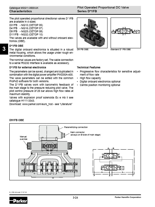
3The pilot operated proportional directional valves D*1FBare available in 4 sizes:D31FB - NG10 (CETOP 05)D41FB - NG16 (CETOP 07)D91FB - NG25 (CETOP 08)D111FB - NG32 (CETOP 10)The valves are available with and without onboard elec-tronics (OBE).D*1FB OBEThe digital onboard electronics is situated in a robustmetal housing, which allows the usage under rough en-vironmental conditions.The nominal values are factory set. The cable connectionto a serial RS232 interface is available as accessory.D*1FB for external electronicsThe parameters can be saved, changed and duplicated incombination with the digital power amplifier PWD00A-400.The valve parameters can be edited with the commonProPxD software for both versions.The D*1FB valves work with barometric feedback ofthe main stage to the pressure reducing pilot valve. Thepilot control pressure of 25 bar allows high flow rates atmaximum stability.Valves with explosion proof solenoids Ex e mb ll seecatalogue HY11-3343.Download: /euro_hcd - see “Literature”D91FB OBED91FB OBETechnical Features• Progressive flow characteristics for sensitive adjust-ment of flow rate• High flow capacity• Digital onboard electronics optional• Centre position monitoring optionalSeries D*1FB3Ordering CodeD*1FB1) With enlarged connections Ø 32 mm.2)Not for spool type B31 und B32.3)Please order plugs separately. See accessories.4)Please order female connector M12x1 separately (see accessories , female connector M12x1 (order no.: 5004109).Series D*1FB3Series D*1FB OBE D*1FB OBEOrdering Code1) With enlarged connections Ø 32 mm.2)Not for spool type B31 und B32.3)Please order plugs seperately, see accessories .4) For 1 solenoid 0...+10 V respectively 4...20 mA.5) Not for spool position E and K.6) F0, M0 potentiometer supply, W5 command channel & potentiometer supply.7) Please order female connector M12x1 separately (see accessories , female connector M12x1 (order no.: 5004109)Series D*1FB3Technical Data2)Flow rate for different D p per control edge: Q x = Q Nom. · √ D p xD p Nom.1)If valves with onboard electronics are used in safety-related parts of control systems, in case the safety function is requested, the valveeletronics voltage supply is to be switched off by a suitable switching element with sufficient reliability.Series D*1FB3Technical DataWith electrical connections the protective conductor (PE W) must be connected according to the relevant regulations.Series D*1FB3D*1FB B/E Flow characteristics at D p = 5 bar per metering edge Spool code E01/02Spool codeB31/32*D*1FB B/E OBEFlow characteristics(set to opening point 10 %)at D p = 5 bar per metering edge Characteristic CurvesSpool code E01/02Spool code B31/321)Flow direction depending on ordering code.All characteristic curves measured with HLP46 at 50 °C.Series D*1FB3The neutral position is monitored. The signal changes after less than 10 % of the spool stroke.Monitor SwitchElectrical characteristics of position control M12x1 as per IEC 61076-2-101M12 pin assignment1 + U S 19.2...28.8 V2 Out B: normally open3 0V4Out A: normally closedPlease order female connector M12x1 separately (see accessories, female connector M12x1 (order no.: 5004109).1)Only guaranted with screened cable and female connectorSeries D*1FB3Block DiagramsCode F0, M06 + PE acc. to EN 175201-804Code G0, S06 + PE acc. to EN 175201-804Code W511 + PE acc. to EN 175201-804Series D*1FB3Interface ProgramProPxD interface programThe ProPxD software permits comfortable parameter setting for the module electronics. Via the clearly arranged entry mask the parameters can be noticed and modified. Storage of complete parameter sets is possible as well as printout or record as a text file for further documenta -tion. Stored parameter sets may be loaded anytime and transmitted to other valves. Inside the electronics a non-volatile memory stores the data with the option for recall-ing or modification.The PC software can be downloaded free of charge at /isde – see page “Support" or directly at /propxd.Features• Comfortable editing of all parameters• Depiction and documentation of parameter sets • Storage and loading of optimized parameter adjust -ments• Executable with all actual Windows ® operating systems from Windows ® XP upwards•Plain communication between PC and electronics via serial interface RS232CThe parametrizing cable may be ordered under item no. 40982923.Series D*1FB3Pilot FlowD31FBB/ED41FBB/ED91FBB/ED111FBB/EPilot oil inlet (supply) and outlet (drain)Series D*1FB3DimensionsD31FBD41FBSeries D*1FB3D91FBDimensionsD111FBSeries D*1FB3Dimension with DT04-2P "Deutsch" ConnectorDimensionsSeries D*1FB3Series D*1FB OBEDimensionsD31FB OBED41FB OBESeries D*1FB3Series D*1FB OBE D91FB OBEDimensionsD111FB OBE。
蓝熊蓝熊下地拉力机说明书

ADVANTAGES: WIRELESS REMOTE PROVIDES MAXIMUM FLEXIBILITY FOR OPERATOR
EASY SET-UP RUGGED DESIGN TO WITHSTAND HARSHEST CONDITIONS
EASY LAYOUT FOR MAINTENANCE AND SERVICE HYDRAULICALLY-CONTROLLED ARM AND OUTRIGGERS
ASK ABOUT THE CUSTOMIZED AND FLEXIBLE LEASING & FINANCING SOLUTIONS AVAILABLE FROM CUSTOM TRUCK CAPITAL
........... ..........
PULL SPEED: 56FPM: 8,500 LBS. 79FPM: 6,000 LBS. 175FPM: 2,300 LBS.
THE BLUE OX CONTROL BOX: REAL-TIME TENSION MONITORING
DOWNLOADABLE PULL DATA WIRELESS/BLUETOOTH REMOTE CONTROL
SUPERIOR FACTORY SERVICE AND SUPPORT INSTRUCTIONAL VIDEO AND SERVICE MANUAL PROVIDED
FEATURES: HYDRAULIC BOOM ARM EXTENSION (UP TO 90”)
ADJUSTABLE OUTRIGGERS EASY-TO-ACCESS MAINTENANCE COMPONENTS
TRAFFIC CONE HOLDER UMBRELLA HOLDER WITH UMBRELLA INCLUDED
- 1、下载文档前请自行甄别文档内容的完整性,平台不提供额外的编辑、内容补充、找答案等附加服务。
- 2、"仅部分预览"的文档,不可在线预览部分如存在完整性等问题,可反馈申请退款(可完整预览的文档不适用该条件!)。
- 3、如文档侵犯您的权益,请联系客服反馈,我们会尽快为您处理(人工客服工作时间:9:00-18:30)。
LANDesk产品手册2010目录一. 桌面管理中遇到的问题 (1)1 桌面为什么需要管理 (1)2 桌面如何管理 (1)二.LANDesk解决方案介绍 (3)1 LANDesk公司简介 (3)2 LANDesk产品列表 (3)3 LANDesk解决方案功能及卖点 (5)3.1 管理解决方案产品简介 (5)资产管理 (5)远程支持 (7)软件分发 (8)软件授权监视 (10)操作系统分发和配置迁移 (11)LANDesk应用程序虚拟器(插件) (14)3.2 安全解决方案产品简介 (16)LANDesk补丁管理器(插件) (16)防病毒软件病毒代码管理 (19)桌面防火墙管理 (19)安全威胁分析 (20)蓝代斯克更新 (20)软件禁用 (20)间谍软件检测和排除 (21)设备外设控制 (21)LANDesk主机入侵防护系统(插件) (22)客户端安全准入 (23)LANDesk 防病毒软件(插件) (24)4 LANDesk管理方案特点 (26)三. LANDesk解决方案案例(部分) (28)附录1 产品价格表 (28)附录2 产品架构 (30)单一服务器部署架构 (30)网络拓扑图 (30)节点说明 (30)管理模式介绍 (31)管理角色划分 (31)系统维护 (32)系统安全 (33)附录3 软件分发技术 (34)有目标的多址广播 (34)对等下载 (36)字节级的断点续传技术 (37)动态带宽调整技术 (37)一.桌面管理中遇到的问题1桌面为什么需要管理现在,随着企业IT应用的不断深入和普及,拥有数百台甚至成千上万台个人电脑、服务器和移动设备的企业越来越多。
如何对它们进行高效率的管理?这已成为令CIO们头痛的事情。
比如,当微软发布了一个新的Windows补丁程序时,如果是有30~40台PC的企业,网管员可以逐一去打补丁,但如果一个公司有1000多台电脑,IT管理人员却非常有限,而且还有外地的分支机构,怎么办?而且这些电脑运行着各种前端企业应用,其稳定性、可靠性、安全性及性能不仅直接影响员工的工作效率,也对整个企业的业务效率和管理成本有着重要影响。
与此同时,由于个人电脑和移动设备的使用自主性大,桌面的内容和应用往往因人而异,不按要求及时升级安全补丁软件、安装未经授权的软件都可能导致桌面端设备和移动设备成为企业IT管理“木桶效应”中的“最短木块”。
对桌面设备、服务器和移动设备管理程度的高低直接决定着IT设备的应用效能和企业整体IT系统成本的控制。
据Gartner对IT系统成本分析报告,在整个企业的IT系统成本中,由于终端用户操作不当而带来的成本增加已高达48.7%。
而这些成本往往都是计划外的支出。
因此,企业级用户的桌面管理已成为一个重要的IT管理问题。
2桌面如何管理何为桌面管理?简单地说,桌面管理就对企业IT系统中的桌面设备进行全面的管理,保证企业IT系统稳定、安全、可靠地运行。
我们先来看一下,一台设备从采购到淘汰需要经过怎样的使用生命周期呢?用户在采购设备之后,首先要登记设备的硬件配置,然后安装并配置操作系统;安装应用软件、配置应用环境,一切OK之后,设备进入使用阶段,需要进行日常维护,解决可能出现的问题;实施必须的管理策略,跟踪用户应用的使用情况;统计设备从硬件到软件的IT资产并形成报告;保障设备系统和应用的安全性;升级设备的硬件和软件环境。
对这个使用生命周期的每一过程进行管理,就是桌面管理所需要涉及的内容。
一般来说,桌面管理涵盖的范围包括IT资产的统计和追踪、软件和操作系统的安装、日常维护、安全监控和管理、应用监控和服务器管理等。
IT资产的统计和追踪“企业到底有多少IT资产?这些资产的实时状态如何?”这是企业IT管理的基础问题。
企业不仅需要了解系统硬件构建的IT资产信息,而且还要包括安装的操作系统和应用名称、版本以及系统的配置信息,比如机器名、用户、IP地址等,这些资产信息都是随时更新的。
软件和操作系统的安装在企业新购设备,或在操作系统崩溃后,第一件要做的事就是安装或恢复操作系统和应用,如果只能在设备本地逐台操作,显然费时费力。
企业需要对网络中客户端的操作系统和应用程序进行统一的安装和配置,提高管理效率,更赢得宝贵的时间。
日常维护很多IT管理员往往疲于应对电话求助和现场服务,工作效率非常低,而且大部分是重复性的简单劳动。
企业需要IT管理员能够远程解决问题,只有在特殊情况下才到现场支持,从而大幅度提高支持效率。
安全监控和管理安全漏洞、恶性病毒、黑客攻击等事件常常给企业来严重的灾难。
企业需要能够统一掌握终端设备的漏洞状况,了解网络终端的平台安全性,包括用户的共享安全性、密码安全性、IE安全性等,并能统一应用安全补丁,实施安全策略并及时反馈效果。
应用监控一些终端用户安装一些业务无关的应用程序,比如聊天工具、游戏等,这些应用的使用不仅影响员工的工作效率,更影响网络的性能。
企业需要实时地对用户的应用使用情况进行详细的跟踪并严格限定某些无关应用的使用。
服务器管理现在,企业中的PC服务器数量逐渐增加,但对服务器的维护和管理主要还是通过每天定时的人工监视和用户的问题反馈来实施。
企业需要对服务器的关键硬件和操作系统资源进行实时监控,当出现安全、功能或性能问题时实时报警、响应并记录日志。
以上的管理工作仅靠简单的手工维护方式已经无法胜任,企业需要更好的桌面和设备管理工具,在IT系统生命周期的每个环节中,掌握IT系统资产信息和监控应用系统的应用效率、可靠性和可扩展性,帮助企业维持稳定的业务和收益,在不添置额外软硬件设备的情况下,最大限度地提升IT架构的应用价值和安全保障。
二. LANDesk解决方案介绍1LANDesk公司简介LANDesk软件公司是业界领先的桌面设备,服务器和移动设备的管理和安全解决方案提供商。
自2002年从Intel拆分出来后,保持了50%以上的高速增长。
其产品线以LANDesk管理套件为核心,扩展了补丁管理器、桌面安全管理套件、系统管理器、服务器管理器、手持设备管理器等多个产品和插件。
在企业网络终端设备的管理和安全防护领域提供了全面的解决方案。
在2006年4月27日,蓝代斯克与美国Avocent公司签署最终协议,Avocent 收购蓝代斯克软件公司。
蓝代斯克将成为Avocent的独立业务部门,充分利用双方合并后在硬软件方面的协力优势,提供业界唯一的“不间断”管理解决方案,蓝代斯克与Avocent联合起来,将能够提供一系列完整的管理解决方案,它们具有无与伦比的端到端应用范围、适用于从数据中心直到终端节点的各个领域。
LANDesk中国分公司于2003年初在北京建立,现在在上海,广州,香港、台北有办事机构。
到目前为止已经发展成为具有研发,测试,销售,市场等完整架构的营运中心,员工共160多人,可以为国内市场的用户提供即时高效的服务和支持。
到目前为止,在银行,电信,移动,联通,交通,石化,传媒、政府等领域拥有众多的用户。
2LANDesk产品列表3LANDesk解决方案功能及卖点我们希望通过使用蓝代斯克产品帮助客户对其桌面系统的整个IT生命周期进行管理,包括设备的购置、安装、日常维护、管理、系统升级、迁移到报废的完整过程;另外通过我们的产品实现对桌面系统日常使用中的安全管理,包括持续更新补丁、间谍软件防护、杀毒软件管理、防火墙管理等等。
3.1 管理解决方案产品简介在现代企业环境下,一个IT的管理部门需要花费大量的人力物力来维护企业的计算机运行环境。
同时,由于计算机设备的更新和变化,财务部门对企业的计算机设备的管理和统计经常处于一种无序及手工统计的状态,当设备更新频繁时,原本的设备管理记录往往由于管理的滞后和对实际情况的掌握程度不够无法及时更新,从而造成设备管理的混乱还会造成时间的迟滞,影响企业的运行效率,给企业带来损失。
如何解决这些痛苦的管理问题?您需要一套高效和易于使用的桌面管理解决方案。
LANDesk管理套件通过以下功能模块实现IT资产全生命周期的管理:资产管理远程支持Q:可以对哪些平台进行远程支持?A:Windows , Mac , Linux。
Q:对慢速网络的客户端怎样进行远程支持?A:远程支持可以根据连接的网络进行调节,支持局域网、宽带甚至拨号。
对于慢速网络,远程支持功能会自动挂起客户端的桌面图片仅使用蓝色的桌面。
并且会通过降低截屏的帧数,减少传输的色彩信息等等,减少传输的数据,保证远程支持的响应速度。
Q:远程支持的安全性怎么保证?A:1、管理员如果要对某台设备进行远程支持需要核心服务器来建立连接,核心服务器会验证登录的管理员的口令是否正确,要管理的客户端是否属于该管理员的管理范围;2、核心服务器发送远程支持指令调用客户端的相关代理,客户端通过证书验证核心服务器发来的指令,如果验证通过则客户端打开代理接受管理员的管理;3、管理员使用的控制台和客户端的远程支持代理根据会话密钥建立连接,开始进行远程支持。
控制台和被控制的客户端直接传输的数据和指令全都通过SSL加密。
4、远程支持技术后,控制台和被控制的客户端之间的连接中断,本次会话密钥作废。
5、建立远程支持连接、传送指令、远程执行等操作,核心服务器都会留下日志记录。
软件分发软件授权监视Q:统计许可证数量,是否区分正版盗版?A:由客户端代理扫描客户端机器上安装的应用程序,只要发现应用程序的特征文件就算是一个安装,不论是正版还是盗版。
而且对于很多企业版软件,安装介质都是相同的,序列号或者注册码也是相同的,只是许可证协议上有安装节点数的规定。
规定数量内的安装就是正版,超过规定数量的安装就是盗版,就有可能被罚款。
使用蓝代斯克管理套件提供许可证监控功能,通过客户端代理核心服务器可以收集客户端上所有安装的软件的列表,统计安装的总数量。
Q:绿色软件能否被发现?A:默认情况下,客户端代理只扫描注册表中的软件安装信息,也就是“添加删除程序”中显示的信息,绿色软件因为不需要安装就可以直接运行所以在注册表中没有记录。
如果采用扩展扫描,则客户端代理可以扫描机器上所有EXE文件的信息。
绿色软件也能被发现和跟踪。
Q:许可证信息是哪里来的?A:由管理员人工输入许可证信息,包括数量、序列号、购买日期、金额等信息。
蓝代斯克提供的是第三方的桌面管理工具,收集的许可证信息仅提供给客户自己使用,绝对不会向外发送,造成泄密。
Q:对离线设备怎样监视软件使用情况?A:客户端代理程序会始终跟踪监视软件的使用情况,并将记录结果存在客户端注册表中,当离线设备重新接入网络时,软件使用情况的数据会随同清单扫描数据一起上传的核心服务器,则离线时软件的使用情况数据也可以传送到核心服务器上。
Q:软件改名之后是否还可以禁用?A:可以。
禁用的软件列表不仅包括软件的文件名,还包括该文件的属性,文件头等信息。