基于Arduino制作的触摸变色台灯(附原理图、PCB板图、实物图、测试流程、源代码)
智能灯触摸台灯制作资料程序+原理图pcb分享给大家

智能灯触摸台灯制作资料程序+原理图pcb分享给大家such808发表于 2015-7-25 13:17:12 | 只看该作者 |只看大图上传资料希望各位喜欢程序预览:1.#include<reg52.h>2.fanhui();3.duanma[]={0xC0,0xF9,0xA4,0xB0,0x99,0x92,0x82,0xF8,0x8 0,0x90};//共阳数字段码 0-94.sbit g1=P2^1;sbit g2=P2^3;sbit g3=P2^5;sbit g4=P2^7; //位选5.sbit key1=P1^1;sbit key2=P1^5;sbit key3=P1^7;//按键6.sbit spek=P1^0; //蜂鸣器7.sbit powr=P2^0; //继电器开关8.sbit chumo=P1^3; //触摸选项9.char sum=0,s=59,min=0,h=0,add=0;10.void delay()11.{12.int a,b;13.for(a=10;a>0;a--)14.for(b=50;b>0;b--);15.}16.delay1()17.{18.int a,b;19.for(a=50;a>0;a--)20.for(b=300;b>0;b--);21.}22./////////////////////////////////////////////////////23.////////////////////时间处理函数/////////////////////24./////////////////////////////////////////////////////25.jishi()26.{27.if(s<0)28.{29.s=59;min--;30.}31.if(min<0)32.{33.min=59;34.h--;35.}36.if(h<0)37.{38.h=23;39.}40.}41./////////////////////////////////////////////////////42.////////////////////显示函数/////////////////////////43./////////////////////////////////////////////////////44.xianshi()//45.{46.P0=duanma[h/10];////小时显示47.g1=0;48.delay();49.g1=1;50.P0=duanma[h%10];51.g2=0;52.delay();53.g2=1;54.if(add>25)55.{56.P0=duanma[min/10]+0x80;/////分显示57.g3=0;58.delay();59.g3=1;60.P0=duanma[min%10]+0x80;61.g4=0;62.delay();63.g4=1;64.}65.else66.{67.P0=duanma[min/10];/////分显示68.g3=0;69.delay();70.g3=1;71.P0=duanma[min%10];72.g4=0;73.delay();74.g4=1;75.}76.}77.//////////////////////////////////////////////////////78.////////////////待机程序/////////////////////////////79./////////////////////////////////////////////////////80.daiji()81.{82.powr=1;83.g4=g3=g2=g1=1;84.delay1();delay1();delay1();delay1();delay1();85.while(1)86.{87.delay1();delay1();88.if(chumo==1)89.{90.delay();91.if(chumo==1)92.{93.while(chumo==1);94.spek=0;95.delay1();96.spek=1;97.sum=0,s=59,min=0,h=0,add=0;//重新对初始变量赋值98.powr=0;99.break;100.}101.}102.}103.fanhui();//重头开始104.}105.//////////////////////////////////////////////////////// 106.//////////////////返回起始点////////////////////////////// 107.///////////////////////////////////////////////////// 108.fanhui() //开始标号109.{110.while(1) //预备显示111.{112.g1=g2=g3=g4=0; //显示三条横线(---)0xbf113.P0=0xbf;114.delay1();115.delay1();116.delay1();117.delay1();118.g1=g2=g3=g4=1;119.delay1();120.delay1();121.delay1();122.delay1();123.124.if(key1==0)125.{126.spek=0;127.delay1();128.if(key1==0)129.while(key1==0);130.spek=1;131.break;132.}133.if(chumo==1) ///////检测有无关闭指令134.{135.delay1();delay1();delay1();delay1(); 136.if(chumo==1)137.{138.while(chumo==1);139.spek=0;140.delay1();141.spek=1;142.daiji();143.}144.}145.}146.}147.///////////////////////////////////////////////////// 148.////////////////////按键函数///////////////////////// 149.///////////////////////////////////////////////////// 150.anjian()151.{152.if(chumo==1)153.{154.delay1();delay1();155.if(chumo==1)156.{157.while(chumo==1);158.spek=0;159.delay1();160.spek=1;161.daiji();162.}163.}164.if(key1==0)165.{166.delay1();167.if(key1==0)168.{169.spek=0;170.delay1();171.spek=1;172.while(key1==0);173.while(1)174.{175.P0=duanma[h/10];////小时显示176.g1=0;177.delay();178.g1=1;179.P0=duanma[h%10];180.g2=0;181.delay();182.g2=1;183.P0=duanma[min/10]+0x80;/////分显示184.g3=0;185.delay();186.g3=1;187.P0=duanma[min%10]+0x80;188.g4=0;189.delay();190.g4=1;191.while(add>49)192.{193.g1=g2=g3=g4=1;194.}195.if(key2==0) //时调整加、、、、、、、、、196.{197.delay1();198.if(key2==0)199.{200.spek=0;201.delay1();202.spek=1;203.if(h==24)204.{205.h=0;206.}207.else208.h++;209.}210.}211.if(key3==0) //分调整加、、、、、、、、、212.{213.delay1();214.if(key3==0)215.{216.spek=0;217.delay1();218.spek=1;219.if(min==60)220.{221.min=0;222.}223.else224.min++;225.}226.}227.if(key1==0) //调试确定并退出调试状态228.{229.delay();230.if(key1==0)231.{232.spek=0;234.spek=1;235.while(key1==0);236.break; //跳出本while语句,即本函数结束237.}238.}239.}240.}241.}242.}243.///////////////////////////////////////////////////// 244.////////////////////主函数/////////////////////////// 245.///////////////////////////////////////////////////// 246.void main()247.{248.TMOD=0x01;249.TH0=(65535-20000)/255;250.TL0=(65535-20000)%255;251.EA=1;252.ET0=1;253.TR0=1;254.chumo=0;255.while(1)256.{257.if(chumo==1)258.{259.delay1();260.if(chumo==1)261.while(chumo==1);262.spek=0;264.spek=1;265.powr=0;266.break;267.}268.}269.fanhui(); //调用初始返回函数270.while(1) //执行主程序271.{272.xianshi();273.anjian();274.if(h==0)275.{276.if(min==0)277.{278.if(add<25)279.{280.g4=g3=g2=g1=1;281.delay1();282.delay1();283.delay1();284.delay1();285.}286.if(s==0)287.{288.daiji();289.}290.}291.}292.}293.}294.///////////////////////////////////////////////////// 295.////////////////////秒表定时中断服务函数///////////// 296.///////////////////////////////////////////////////// 297.dingshi()interrupt 1298.{299.TH0=(65535-20000)/255;300.TL0=(65535-20000)%255;301.add++;302.if(add==50)303.{304.add=0;305.s--;306.jishi();307.}308.}复制代码。
触摸调光台灯
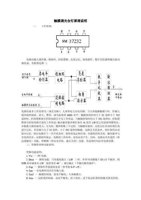
触摸调光台灯原理说明一、工作原理:SM电路由输入缓冲器、锁相环、控制逻辑、亮度记忆、相角指针、数字比较器和输出驱动器组成。
其框图见图一:电路的基本工作原理为(调光为例):人体带电与市电同频,当人体接触触摸片时,经输入缓冲级的削波、放大、整形,成为标准的MOS电平。
触摸持续时间大于32毫秒小于332毫秒时,控制逻辑部分控制电路呈开关工作状态。
当触摸持续时间大于332毫秒时,控制逻辑部分控制电路呈调光工作状态,输出触发脉冲相位角在41度至159度之间连续周期变化,并根据人眼的感受力,分为快、慢和暂歇三个过程。
当触摸结束时,亮度记忆对该时相位角进行记忆,若再施与大于32毫秒,小于332毫秒的触摸,电路呈关状态时,相位角仍由该部分记忆,保证电路在下一次开状态时,保持原选定相位角,光源保持原亮度。
触发脉冲与市电的同步,由锁相环保证,电路的工作时钟,也均由其产生。
同时,电路还具有遥控(即远端触发)功能,和渐睡(即由亮至暗,最后关闭)功能,其延续时间由外电路设置。
三、管脚排列和功能说明:管脚功能说明:1. Vss —5V电源。
2. Doze —渐暗功能。
当导通角最大(159°)时。
外界对该脚施于83±3个脉冲,则SCR的导通角从159°连续变至40°,最后截止(不输出触发脉冲)。
3. Cap —锁相环外接滤波电容(参考值0.47μF)。
4. Syn —市电频率同步信号输入端。
5. Sen2 —触摸控制端。
低电平触发,人体触摸点。
6. Sala —远距离控制端。
高电平触发,抗干扰好,适于较远距离的按键式调光控制。
7. VDD —0V。
8. Out —输出触发脉冲。
触摸调光台灯原理图普通台灯加装此套件可使普通台灯升级为“节能+视力保健”型台灯,它具有触摸开关灯、触摸调光和测光功能,本电路主要采用了一块新型专用调光集成电路SM7232。
该集成电路的主要电参数为:工作电压4.5~4.9V,静态电流400μA,可控制50Hz及60Hz交流电。
触摸式带记忆台灯调光电路设计
该调光台灯开关摆脱了传统的机械式拨动开关调光,电位器调等形式,通过 人手触摸电极片(金属片)来实现对灯光的开,关及连续调光控制。
2.2 电路原理
触摸式调光台灯开关的电路图如图 4 虚线右边所示。左边是为了便于说明电 路原理而绘出的被控台灯电路。在该电路图中,H 为不大于 100W 的白炽灯,可用 1A/400V 的双向晶闸管 VS 来控制。若白炽灯功率大于 100W,则应该相应加大双 向晶闸管 VS 的额定电流(最大可达 10A)。芯片 A(NB7232)使用的 5V 直流电源直 接由 VD1,VD2,R1 与 C1 组成电阻降压半波整流稳压电路从 220V 交流市电中获取。 同时,市电经 C2 虑出尖脉冲干扰,由 R2 将截取捕获的 过零同步信号送入芯片 NB7232 的同步输入端,使内部锁相环电路与市电保持同步 相角。VD3 作为放电二极管,用于保护 C2 不被击穿。C3 是芯片内部锁相环电路 的外接虑波电容器。电容器 C4 用于降低 8 脚输出的控制脉冲电压,R3 为双向晶 闸管 VS 控制极的限流,隔离电阻器,它可以防止因晶闸管 VS 控制极出现故障高 压而导致芯片 NB7232 的损坏。M1 为手触电极片,用铁片或黄铜片等材料加工而 成,形状和大小均无严格要求。R5, R6 为两只串连的高阻电阻器, 阻值之和应大于 6 M,而且不能用一个电阻器来代替。这样,使用中 万一有一个电阻器受潮或碰触短路,也能确保使用者的安全。人体触 摸信号(与市电同频率的微弱交流电泄漏信号)经过保安电阻器 R5,
图2
波,放大,整形成为标准的 MOS 电压。当手指触摸时间大于 32 毫秒,小于 332 毫秒时, 控制逻辑控制芯片电路呈开关工作状态。当触摸时间大于 332 毫秒时, 控制逻辑控 制芯片电路呈调光工作状态, 输出触发(可控硅)脉冲相位角在,之间连续周期变化 (根据人眼的感受力,分为快,慢和暂停三个过程)。当停止触摸时, 亮度记忆电路对该 时刻相位角进行记忆,若再施与大于 32 毫秒,小于 332 毫秒的触摸, 电路即呈关状态, 相位角仍由该部分进行记忆保证电路在下一次呈开状态时, 保持上次选定相位角, 光源保持原亮度。该芯片要求输出触发(可控硅)脉冲与市电同步,这由锁相环电路保 证, 电路的工作时间也由它产生。同时,该芯片电路还具有遥控(即远端触发)功能 和渐睡(即由亮到暗,最后关闭熄灭)功能,其延续时间可由外电路设置。
基于Arduino的电子调光台灯设计

拟信号的电平进行编码通过调制方波的占空比来实现ꎮ 电
量并显示电子调光台灯的工作电压、电流、功率数据ꎬ实时显
压则是以一种通或断的重复脉冲序列被加到模拟负载上去
示人体与电子调光台灯的距离ꎬ当距离小于设定值时发出警
的ꎮ 占空比是指有效电平在一个周期之内所 也可设定
灯工作时的电压、电流、功率时ꎬ可能由于此仪器不能同时测
得电压和频率的变化ꎬ接线错误导致 PWM 损坏ꎮ
烧录程序并供电ꎬ调试超声波测距模块及显示器显示距
离ꎬ通过串口传回数据实时检测超声波工作状态ꎮ 通过串口
用同样的方法调试光敏传感器及其他模块的工作状态ꎮ 测
试得各模块工作正常ꎬ程序与硬件连接良好ꎮ
图 2 电路原理图
随着科技全球化ꎬ越来越多的新技术被创造出来ꎬ我们
影响ꎮ 所以本设计控制系统采用在 Arduino 扩展板上搭建单
片机技术和 PWM 调节方式结合起来实现台灯光强调节ꎮ 通
少ꎬ价格较贵一些ꎮ
切换控制ꎬ包含全亮和熄灭ꎮ 通过将环境光传感器、超声波
实现变电压
的生活方式在科技创新中不断地被更新ꎮ 本设计通过将单
摘 要:将 220V 交流电变为 5V 电源( 直流电) 供电给 ArdunioꎬArduino 通过 PWM 方式控制与电源并联的可控硅模块ꎬ实
现变电压ꎮ 感知环境功能用 Arduino 连接各种各样的传感器来实现ꎬ反馈、影响环境功能用 Arduino 控制灯光、马达和其他的
装置来实现ꎮ
关键词:ArduinoꎻPWMꎻ可控硅模块ꎻ自动调节ꎻ交直流转换器
过电子调光台灯上的亮度增减按键ꎬ实现其多个档位的亮度
传感器、LCD 显示屏、蜂鸣器连接到 Ardunioꎬ来实现根据环
片机ꎬ这种方法比面包板搭建方便、简单ꎬ易于搭建ꎬ连线较
毕业设计(论文)-触摸式调光台灯设计[管理资料]
![毕业设计(论文)-触摸式调光台灯设计[管理资料]](https://img.taocdn.com/s3/m/0e9d191ef8c75fbfc67db274.png)
学士学位毕业设计(论文)触摸式调光台灯设计学生姓名:学号:2XX指导教师:所在学院:信息技术学院专业:电子信息工程中国·大庆2013 年 5 月摘要台灯是人们生活中用来照明的一种家用电器。
随着社会的发展和科技的进步,台灯的种类、样式,以及其功能越来越多。
技术上在不断的突破和完善,满足了人们的日常需求。
此次设计的触摸式调光台灯相比传统的按键式台灯更为方便和灵敏。
采用LED灯更加的节能和环保,而且还可以根据不同人的需求调节不同的亮度。
本文介绍了以SGL8022W芯片为控制核心,用12V稳定电源,通过触摸来调节不同光度。
该触摸式调光台灯电路并不复杂,很大程度上节省电能,延长LED灯寿命,经济适用。
本次课题的研究不仅可以使自己更加了解专业知识还可以对市场上台灯的设计起到一定的参考作用,设计出更加合理便捷的产品来满足人们生活中的需要。
关键词:触摸式LED台灯SGL8022W 调光ABSTRACTThe lamp is used to illuminate a household appliances in people's lives.With the development of society and the advancement of technology,lamp type, style, and more and more powerful.Technical breakthrough in constant and perfect,to meet the daily needs of the people.The design of the touch lamp dimmer compared to traditional push-button lamp is more convenient and sensitive.LED lights more energy-saving and health,but also according to the needs of different people of different brightness.This article describes that the SGL8022W chip as the control core,stable power supply with12V touch to adjust the different luminosity.The touch dimmer lamp circuit is not complicated,largely to save energy and prolong the life of LED lights, affordable.The research projects can not only a better understanding of expertise can also play a reference role in the design of the lamp market design more reasonable and convenient products to meet the needs of our lives.Keywords:Touch LED lamp SGL8022W Dimming目录摘要 (I)ABSTRACT (II)前言 (IV)1 绪论 (3) (3) (5)2 硬件电路设计 (6) (6)12V直流电源设计 (8) (10) (12) (17)3 电路调试与功能实现 (18) (18) (18)4 总结与体会 (20)结论 (20)参考文献 (22)致谢 (23)附录.................................... 错误!未定义书签。
基于单片机的智能LED台灯设计,附电路图、成品演示图、源程序

关闭的功能。该传感器检测距离通过编写程序控制。 以上的程序见附录三。
4 总结
该设计实现了自动检测屋内是否有人并自动开启/关闭功能;台灯具有光亮 度调节功能;具有时间显示功能;具有温度显示功能;具有闹铃功能。但在细节 方面还有不足之处。LED 亮度达不到很亮的程度,只能在一个很小的范围变化, 以致于光亮度不够。
附录一 实物照片
附录二 硬件电路图
附录三 程序
#include<reg52.h> #include<shizhong.h> void delay(uint z) {
uint x,y; for(x=z;x>0;x--)
for(y=110;y>0;y--); } void delay1(unsigned char t)
图 9 红外传感电路
检测屋内是否有人我们选用 BIS0001 红外热释传感器,因为该传感器灵敏度 好,好控制,而且价钱不贵。3 脚接电源 VCC,1 脚接地,2 脚通过一个 NPN 型 的三极管接至单片机的 P37 口。由于该传感器的带负载能力较弱,加一个三极管 作为其驱动电路,当 P37 口给低电平时有效。检测距离可通过软件调节。
图 6 时钟模块电路
因为 DS12C887 时钟芯片的集成度都很高,而且它自带锂电池,即使断电了 时钟仍然在工作,所以我们选择了 DS12C887 时钟芯片作为时钟。各脚的连接见 图 6.由于其集成度很高,我们只需按照其数据手册焊接电路即可。 2.6 闹铃模块电路设计 闹铃模块电路如图 7,
图 7 闹铃模块电路
2.2 按键模块电路设计 按键模块电路如图 3,
图 3 按键模块电路
按键 K5、K6 用来调节台灯的亮度,K7 控制模式,即控制台灯是工作在感应 模式下还是工作在手动模式下,亦或是关闭状态。其余的用作调节时钟以及闹铃。 按键均采用低电平有效连接方式。通过按下按键 K5 可以让台灯变暗,按下按键 K6 可以让台灯变亮。其余几个 S1 到 S4 按键可以对时钟进行设置调节,并调节 设置闹铃,当时间与设置的时间一致是闹铃报警,即蜂鸣器响。
基于Arduino开发平台下智能台灯的设计

大多数智能产品原型设计的需要。[2] 1 总体设计 智能台灯的系统首先通过集成蓝牙 4.0 的 Arduino 主控板
与手机蓝牙模块连接,进而与手机端建立通信协议,用 Arduino1.6.8 开发环境向 Arduino 主控板烧录分功能程序代码,实 现台灯功能的设计。手机 APP 通过继电器来控制台灯开关, 灯泡应用雷达感应球,感知人体和光亮变化,再而控制台灯的 开关。台灯通过 UNO 开发板与 Bluno Accessory Shield 扩展 板的连接,其中 RGB LED 集成于扩展板,可以通过手机 APP 显示丰富的颜色,具有良好的夜光效果,并且可实现温度湿度 等环境变量通过 128x64 OLED 显示屏显示手机 APP 端输入 的字符的功能,电路硬件连接图如图 1,2 所示。[4-5]
学科探索
基于 Arduino 开发平台下智能台灯的设计
侯羽张黔
(北京林业大学理学院 北京 100083)
摘 要 Arduino 是目前较为流行的电子互动平台,基于 Arduino 系统的开发,可以制作出集成度高,使用简单的产品,
因为其烧录程序简单,与扩展板和传感器的兼容性较高且价格低廉的特点,在互动电子系统的开发上得到了广泛的应
Abstract The Arduino is a currently popular electronic interactive platform, based on the single-chip microcomputer system development, which can produce an easy-to-use with a high level of integration product. Because of its characteristics of simple burning process, high compatibility with extended board and sensor and the low price, Arduino is widely used in the aspects of electronic system design and interactive product developments. This design is based on the 4.0 Arduino UNO board integrated bluetooth, combining with the characteristics of the development of Smart Home, using the rich integration capabilities of Accessory shields extension board, which realizes the two big functions of showing the corresponding parameters of acquisition through the phone APP and automatic extinguished lamp when people leave the room. Finally, we achieve a high efficiency and energy saving, low cost with a favorable user experience intelligent lamp. Key words Electronic Information Engineering; Intelligent lamps; Arduino; Bluetooth
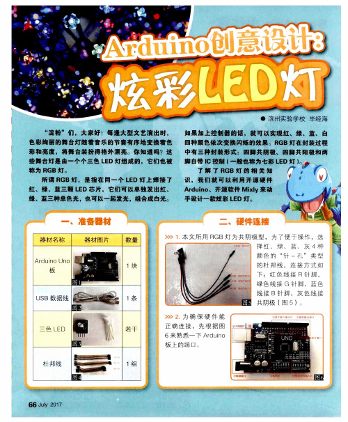
Arduino创意设计:炫彩LED灯
我 们 知道 ,
R GB灯 分 别 连 接 A r d u i n o板 的数 字 端 口5 、6 、9,
只要 分 别将 3个 数 字 端 口设 置 为高 电平 并 上 传
“ 淀 粉 ”们 ,制 作 ቤተ መጻሕፍቲ ባይዱ 了炫 彩 L E D灯 ,可 以 用
3 1 )软 件 为 它 设 计 一 个 漂 亮 的 外 观 ,再 用 3 D打 印 机打 印 出来 。这样 一来 我们 的作 品就 更有 价值 了 , 期待大 家 的精 彩分 享 !
口
A r d u i n o板 的 数 字 端 口 3 、5 、6、9 、
1 0 、1 1 也 可 以作 为模 拟 输 出端 口使 用 ,取
值 范 围 为 0~2 5 5 ,为 了便 于 识 别 ,板 子 上 都标记 了波浪线 。
要 编 程 控 制 R GB灯 每 一 个 灯 的 亮 度 ,我 们 需 要 定 义 3个
择 红 、 绿 、 蓝 、 灰 4种 颜色 的 “ 针 一孔 ” 类 型
Ar dui n o UR O
板
圈 盘 两 I
鳕 ■I
l 1块
的 杜 邦 线 ,连 接 方 式 如 下 :红 色 线 接 R针 脚 , 绿 色 线 接 G 针 脚 ,蓝 色
U S B 数 据 线 嘲 谶
些 舞 台灯 是 由一 个 个三 色 L E D灯 组成 的 。它们 也 被
称为 R GB灯 。
四种颜色依次变换阿烁的效果。R GB灯在封装过程
中有 三 种 封 装 形 式 : 四脚 共 阴 极 、 四脚 共 阳极 和 两 脚 自带 l C控 制 I 一 般也 称 为七彩 了解 了R GB灯 的 相 关 知 识 ,我 们 就 可 以 利 用 开 源 硬 件 Ar d u i n o  ̄开源 软 件 Mi x l y来 动 手设 计 一款炫 彩 L E D灯 。
- 1、下载文档前请自行甄别文档内容的完整性,平台不提供额外的编辑、内容补充、找答案等附加服务。
- 2、"仅部分预览"的文档,不可在线预览部分如存在完整性等问题,可反馈申请退款(可完整预览的文档不适用该条件!)。
- 3、如文档侵犯您的权益,请联系客服反馈,我们会尽快为您处理(人工客服工作时间:9:00-18:30)。
with the necessary connecting hardware. The circuit will be using 3 RGB LEDs. These are common-anode Piranha type available here and contains three LEDs within its body. Each color will need a single dropping resistor (220-ohm for green and blue and 330-ohm for Red). We can also add a small LED with a 1k-ohm as an indicator. The IC we are using is an ATMega-328 microchip, available for about $5 here You will also need a 16Mhz resonator for about 35c, also available at the same site. The development and testing of the software is done using the Arduino system, so a suitable 'host' is necessary. I've used an Arduino 'Nano', a Boarduino and a RBBB board and they all work fine.
Image Notes 1. Modern Device's RBBB (with an ATMega328) acting as the host. Then the 328 is moved over to the circuit board when we're ready. 2. A "USB BUB board" to connect to the chip, and to provide power.
Arduino multi-mode lamp with soft touch switch
by qs on April 24, 2009
Table of Contents Arduino multi-mode lamp with soft touch switch . . . . . . . . . . . . . . . . . . . . . . . . . . . . . . . . . . . . . . . . . . . . . . . . . . . . . . . . . . . . . . . . . . . . . . . . . . . . . . . . . . . . . . . 1
Step 2: Getting started
It is a very good idea to put the microchip in a socket. Here, I've used 2 x 16-pin sockets end-to-end, because that is what I have available... The ATMel chip only has 28w empty sockets on the end. In this picture, the LEDs are along the bottom, with a resistor for each of the primary colors. The little pushbutton on the left is for the Reset, although this is not strictly needed. The yellow blob in the center is the resonator. After I've done the preliminary wiring, the circuit (and programming) is tested through jumpers connected to the 'host', an RBBB (Really Bare Bones Board ), also from Modern Devices. This lets me make sure the wiring is correct before we commit the Microchip. The process is quite straightforward - run / test with the host, then simply transplant the IC over to the circuit board.
Intro: Arduino multi-mode lamp with soft touch switch . . . . . . . . . . . . . . . . . . . . . . . . . . . . . . . . . . . . . . . . . . . . . . . . . . . . . . . . . . . . . . . . . . . . . . . . . . . . . . . . 2 Step 1: What is needed? . . . . . . . . . . . . . . . . . . . . . . . . . . . . . . . . . . . . . . . . . . . . . . . . . . . . . . . . . . . . . . . . . . . . . . . . . . . . . . . . . . . . . . . . . . . . . . . . . . . . . 3 Step 2: Getting started . . . . . . . . . . . . . . . . . . . . . . . . . . . . . . . . . . . . . . . . . . . . . . . . . . . . . . . . . . . . . . . . . . . . . . . . . . . . . . . . . . . . . . . . . . . . . . . . . . . . . . 4 Step 3: A quick test... . . . . . . . . . . . . . . . . . . . . . . . . . . . . . . . . . . . . . . . . . . . . . . . . . . . . . . . . . . . . . . . . . . . . . . . . . . . . . . . . . . . . . . . . . . . . . . . . . . . . . . . 5 Step 4: The circuit . . . . . . . . . . . . . . . . . . . . . . . . . . . . . . . . . . . . . . . . . . . . . . . . . . . . . . . . . . . . . . . . . . . . . . . . . . . . . . . . . . . . . . . . . . . . . . . . . . . . . . . . . . 6 Step 5: The 'Sketch', or program. . . . . . . . . . . . . . . . . . . . . . . . . . . . . . . . . . . . . . . . . . . . . . . . . . . . . . . . . . . . . . . . . . . . . . . . . . . . . . . . . . . . . . . . . . . . . . . 7 Step 6: The latest sketch. . . . . . . . . . . . . . . . . . . . . . . . . . . . . . . . . . . . . . . . . . . . . . . . . . . . . . . . . . . . . . . . . . . . . . . . . . . . . . . . . . . . . . . . . . . . . . . . . . . . . 8 Related Instructables . . . . . . . . . . . . . . . . . . . . . . . . . . . . . . . . . . . . . . . . . . . . . . . . . . . . . . . . . . . . . . . . . . . . . . . . . . . . . . . . . . . . . . . . . . . . . . . . . . . . . . . . 13 Comments . . . . . . . . . . . . . . . . . . . . . . . . . . . . . . . . . . . . . . . . . . . . . . . . . . . . . . . . . . . . . . . . . . . . . . . . . . . . . . . . . . . . . . . . . . . . . . . . . . . . . . . . . . . . . . . . 13
Intro: Arduino multi-mode lamp with soft touch switch
In this Arduino-based project, we will build a lamp with multiple light displays: color sequencer, dimming light, color chaser, firelight - all selected by a touch bar on the circuit board.