汽车电子--点火线圈变压器结构原理
点火线圈的组成结构及工作原理
点火线圈的组成结构及工作原理点火装置的核心部件是由点火线圈和开关装置组成,点火线圈实际上就是一个变压器,将汽车电源供给的低压电转变为高压电,并按照发动机的作功顺序与点火时间的要求适时、准确地配送给各缸的火花塞,在其间隙处产生点火花,点燃气缸内的可燃混合气。
这个看似普通的变压器内部有铁芯、初级绕组、次级绕组和绝缘物质等。
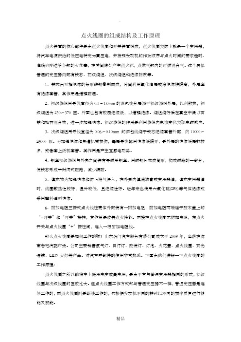
1、铁芯由互相绝缘的条形硅钢叠制而成,片间利用氧化油层或涂绝缘族隔离,外层套有绝缘套管,其作用是增强磁通。
2、初级绕组用导线直径为0.5~1.0mm的漆包线分层绕于初级绕组外层,以利散热,初级绕组为230~370 匝。
外面也包有数层绝缘纸,以增强绝缘。
绕组绕好后在真空中浸以石蜡和松香混合物,进一步加强绝缘。
初级绕组的作用是利用绕组内电流变化实现电磁感应。
3、次级绕组用导线直径为0.06~0.10mm 的漆包线绕于铁芯绝缘套管外部,约11000~26000 匝。
为加强绝缘和免遭机械损伤,每层导线都用绝缘纸隔开,最外层的绝缘纸层数较多,或者套上纸板套管。
其作用是产生互感电动势。
4、钢套初级绕组与外壳之间装有导磁用钢套。
用磁钢片卷成筒形,构成磁路的一部分,使铁芯形成半封闭式磁路,减少漏磁。
5、填充物为加强绝缘和防止潮气浸入,在外壳内填满沥青或变压器油,填充变压器油时,线圈散热性较好,温升较低,且绝缘性好。
近年来也使用六氟化硫(SF6)等气体绝缘或采用塑料造型绝缘。
6、附加电阻三接式点火线柱壳体外部装有一附加电阻,附加电阻两端连于胶木盖上的“+开关”和“开关”接柱,其作用是改善点火性能。
两接柱点火线圈无附加电阻,在点火开关与点火线圈“+”接柱间,连入一根附加电阻线。
那么点火线圈是如何工作的呢?山东名门汽车服务有限公司成立于2009年,坐落在济南老屯汽配市场。
公司主要销售氙气灯、日行灯、改装灯、灯泡、火花塞、点火线圈、双光透镜、LED大灯等产品。
对汽车零部件的使用非常熟悉。
下面由他们讲解一下点火线圈的工作原理:点火线圈之所以能将车上低压电变成高电压,是由于有与普通变压器相同的形式,初级线圈与次级线圈的匝数比大。
高压点火线圈工作原理
高压点火线圈工作原理高压点火线圈是一种用于汽车点火系统的重要部件,它的工作原理是通过变压器的原理将低电压提升为高电压,以产生强大的火花来点燃汽车发动机内燃烧室中的混合气体,从而实现汽车的正常运行。
高压点火线圈一般由铁芯、初级线圈、次级线圈和点火塞连接线组成。
其中初级线圈接收来自汽车电池的低电压,而次级线圈则将低电压变为高电压,供给点火塞产生火花。
当汽车点火开关打开时,电池会将电流通过点火开关传送到初级线圈上。
初级线圈由铁芯绕制而成,当电流通过初级线圈时,会在铁芯中产生一个磁场。
然后,这个磁场会在次级线圈中引起电流的变化,从而产生高电压。
次级线圈由许多匝数较多的细线绕制而成,绕制的匝数远远多于初级线圈。
这样,当初级线圈中的电流发生变化时,次级线圈中的电流也会随之变化。
根据电磁感应的原理,电流变化会在次级线圈中产生一个更大的电磁场。
由于次级线圈的匝数较多,所以次级线圈中的电磁场会比初级线圈中的电磁场更强大。
当电磁场达到一定程度时,就会产生高电压。
这是因为电磁场的变化会引起线圈两端的电势差,从而产生电压。
而由于次级线圈的匝数较多,所以产生的电压也会比初级线圈中的电压更高。
接下来,高压点火线圈会将产生的高电压通过点火塞连接线传送到点火塞上。
点火塞上有两个电极,当高电压通过点火塞时,会在两个电极之间产生一个电火花。
这个电火花的强度很大,足以点燃汽车发动机内燃烧室中的混合气体。
总结起来,高压点火线圈的工作原理是通过变压器的原理,将低电压提升为高电压,以产生强大的电火花来点燃汽车发动机内燃烧室中的混合气体。
它在汽车点火系统中起着至关重要的作用,确保了发动机的正常运行。
同时,高压点火线圈的设计和制造也需要考虑到安全性和稳定性,以保证汽车的可靠性和耐久性。
汽车发动机变压器工作原理
汽车发动机变压器工作原理
汽车发动机变压器是一种电力变换装置,用于将电源电压变换为适合汽车发动机点火系统的高压电流。
工作原理如下:
1. 首先,汽车发动机变压器的低压输入端接收车辆电源系统提供的低电压(通常为12伏特直流电源)。
2. 低压输入端连接到一个由几个线圈组成的电感线圈,称为初级线圈。
3. 当汽车发动机的点火开关打开时,车辆电源系统将电流引入初级线圈,产生一定的电流。
4. 这个电流通过初级线圈时,会导致线圈内部磁场的变化。
5. 然后,这个磁场将传递到与初级线圈相邻的另一个线圈,称为高压线圈或次级线圈。
6. 磁场的变化将导致次级线圈中产生高电压。
7. 这个高电压通过连接到发动机各个点火塞的高压导线传输。
8. 高压电流经过高压导线到达点火塞,用于点燃汽车发动机中的燃气混合物。
9. 此时,汽车发动机变压器完成了低电压到高电压的变换。
总的来说,汽车发动机变压器将来自车辆电源系统的低电压转换为适合点火系统的高电压,以保证汽车发动机的正常运行。
汽车点火线圈原理图

汽车点火线圈原理图
不包含标题的汽车点火线圈原理图如下:
电池的正极通过一根导线连接到一个自感线圈的一端,此自感线圈的另一端连接到恰好靠近一根铁芯的一段导线上。
另一端的导线连接到车辆的点火开关,点火开关可打开和关闭汽车的电路。
在点火开关关闭后,电路中没有电流流动。
当点火开关打开时,电池的正极开始向自感线圈输送电流。
这个电流通过自感线圈产生的磁场作用于铁芯。
铁芯的另一端也有一根导线连接到自感线圈的另一端,形成一个闭合的电路。
在电流通过自感线圈的瞬间,磁场在铁芯中会迅速建立。
在自感线圈的另一端,也会出现一个相同方向的磁场。
这个磁场的快速建立导致自感线圈内的电流迅速增大。
当点火开关关闭后,电池不再向自感线圈输送电流。
这会导致电流突然中断,从而导致磁场在铁芯中迅速消失。
这个瞬间消失的磁场会导致自感线圈内的电流剧烈减小。
磁场的消失还会在自感线圈的另一端产生一个方向相反的磁场。
这个瞬间消失的磁场,以及后面马上生成的磁场,会导致自感线圈内的电流急剧减小,并继续流动。
这种电流的快速变化会产生很高的电压。
这种高电压被传送到火花塞上的电极,产生一个大气的电火花。
这个火花会点燃混
合的空燃比,从而让内燃机正常工作。
总的来说,汽车点火线圈根据电流的快速变化产生高电压,用于点燃引擎中的混合空燃比。
这样,车辆就可以正常启动和运行。
点火的工作原理和工作过程

点火系统故障诊断与排除
汽车电子技术教研室
工作原理
1.点火线圈工作原理
点火线圈其实就是由两组线圈构 成的高压变压器。当初级线圈接通电 源时,随着电流的增长四周产生一个 很强的磁场,铁芯储存了磁场能;当 开关装置使初级线圈电路断开时,初 级线圈的磁场迅速衰减,次级线圈被 一个强大而剧烈变化的磁场吞没。 由于次级线圈的匝数非常大,因此次 级线圈感应出来高电压(最高可达10 万伏)。
一、主要部件工作原理 理
点火线圈 3D
工作原理
2.火花塞工作原理
随着火花塞电极间隙电压的升 高,电极间电场强度不断增大,当 达到某一临界值时(约10000V), 电极间的间隙即形成放电通道而被 “击穿”,形成灼热的气体发光体, 即火花放电现象。放电温度极高, 一般可达2000-3000 ℃ ,足以点燃 气缸内的可燃混合气。
工作过程
3.工作顺序
一般直列四缸发动 机的点火顺序为 1→3→4→2,直列六缸 发动机的点火顺序为 1→5→3→6→2→4。但 也有采用其他点火顺序 的,应以制造厂商提供 的技术数据为准。
二、点火系统工作过程 理
点火控制整个过程 动画
烟台工程职业技术学院汽车工程系
感谢学习
thank you
2.产生电火花的过程
当需要点火时, ECU向点火线 圈发出产生电火花信号,开关管关 断,初级绕组电流突然中断,电流 所产生的磁场ቤተ መጻሕፍቲ ባይዱ然衰减,从而在次 级绕组上产生很高的感应电压,在 高电压作用下,火花塞间隙被击穿, 产生电火花,火花点燃汽缸内经过 压缩的可燃空气。
二、点火系统工作过程 理
奥迪A6点火系统 动画
一、主要部件工作原理 理
点火线圈
一、点火线圈的结构:点火线圈主要由铁芯、绕组、胶木盖、瓷杯等组成;(1) 铁芯由互相绝缘的条形硅钢叠制而成,片间利用氧化油层或涂绝缘族隔离,外层套有绝缘套管,其作用是增强磁通。
(2) 初级绕组用导线直径为0.5~1.0mm的漆包线分层绕于初级绕组外层,以利散热,初级绕组为230~370 匝。
外面也包有数层绝缘纸,以增强绝缘。
绕组绕好后在真空中浸以石蜡和松香混合物,进一步加强绝缘。
初级绕组的作用是利用绕组内电流变化实现电磁感应。
(3) 次级绕组用导线直径为0.06~0.10mm 的漆包线绕于铁芯绝缘套管外部,约11000~26000 匝。
为加强绝缘和免遭机械损伤,每层导线都用绝缘纸隔开,最外层的绝缘纸层数较多,或者套上纸板套管。
其作用是产生互感电动势。
(4) 钢套初级绕组与外壳之间装有导磁用钢套。
用磁钢片卷成筒形,构成磁路的一部分,使铁芯形成半封闭式磁路,减少漏磁。
(5) 填充物为加强绝缘和防止潮气浸入,在外壳内填满沥青或变压器油,填充变压器油时,线圈散热性较好,温升较低,且绝缘性好。
近年来也使用六氟化硫(SF6)等气体绝缘或采用塑料造型绝缘。
(6) 附加电阻三接式点火线柱壳体外部装有一附加电阻,附加电阻两端连于胶木盖上的“+开关”和“开关”接柱,其作用是改善点火性能。
两接柱点火线圈无附加电阻,在点火开关与点火线圈“+”接柱间,连入一根附加电阻线。
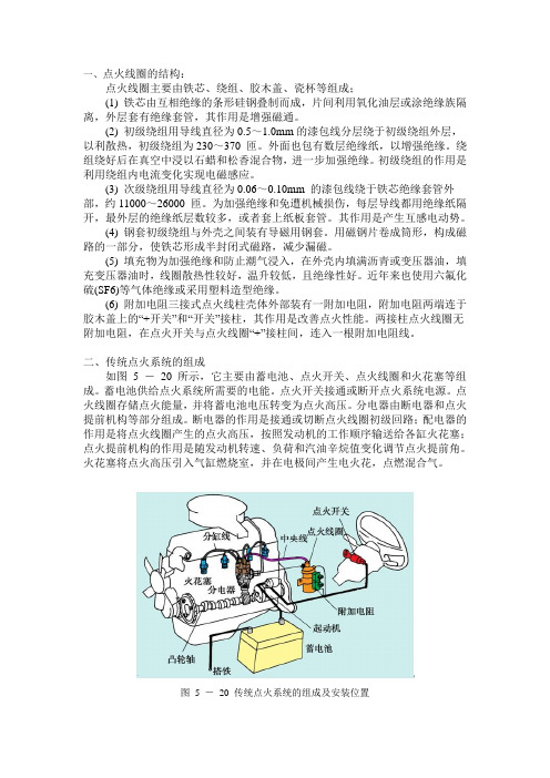
二、传统点火系统的组成如图 5 -20 所示,它主要由蓄电池、点火开关、点火线圈和火花塞等组成。
蓄电池供给点火系统所需要的电能。
点火开关接通或断开点火系统电源。
点火线圈存储点火能量,并将蓄电池电压转变为点火高压。
分电器由断电器和点火提前机构等部分组成。
断电器的作用是接通或切断点火线圈初级回路;配电器的作用是将点火线圈产生的点火高压,按照发动机的工作顺序输送给各缸火花塞;点火提前机构的作用是随发动机转速、负荷和汽油辛烷值变化调节点火提前角。
火花塞将点火高压引入气缸燃烧室,并在电极间产生电火花,点燃混合气。
车用点火器原理 -回复

车用点火器原理-回复车用点火器是指用于启动和点燃内燃机的装置。
它的原理主要包括电源供电、点火线圈变压、点火信号控制和火花塞点火的过程。
下面,我将详细介绍车用点火器的工作原理。
首先,车用点火器需要一个电源来提供能量。
一般情况下,车辆的电源是电瓶,它可以为点火器提供所需的电力。
电瓶通常位于车辆引擎舱的一侧,并通过电源线与车用点火器连接。
其次,点火器内的点火线圈起到变压的作用。
点火线圈由两个线圈组成,一个称为初级线圈,另一个称为次级线圈。
当电源通电时,初级线圈中的电流会在磁铁的作用下产生磁场。
当电源断开时,磁场会导出次级线圈。
由于次级线圈的匝数相对较多,因此会产生较高的电压,这个高压电流会传送到火花塞。
接下来,点火信号控制是车用点火器的一个关键部分。
它负责控制点火器何时进行点燃。
通常,点火信号是由车辆控制模块(ECU)产生的。
ECU 会监测各个传感器,如发动机转速传感器、氧气传感器等,根据这些传感器的数据来确定何时点火。
一旦ECU确定点火的时机,它将向点火器发送点火信号。
最后,火花塞点火是点火器的最后一个步骤。
火花塞是点火器中的核心部件,它负责在汽缸内产生高温的火花,以点燃混合气体。
当点火信号到达点火器时,点火线圈会将高电压传送到火花塞,从而产生火花。
这个火花将点燃汽缸中的混合气体,使其爆炸,进而驱动汽缸的活塞运动,带动整个发动机工作。
总结起来,车用点火器的工作原理是电源供电、点火线圈变压、点火信号控制和火花塞点火的过程。
它需要一个电源提供能量,并通过点火线圈将电压变压后传送到火花塞。
点火信号控制是车用点火器的关键部分,它根据车辆的传感器数据确定点火时机,并将点火信号发送给点火器。
最后,火花塞点火将点燃汽缸内的混合气体,使发动机正常工作。
车用点火器的原理如此,它在车辆的启动和运行过程中起到至关重要的作用。
燃油汽车变压器工作原理

燃油汽车变压器工作原理
一、汽车变压器的基本原理
汽车变压器是由铁芯和绕组构成的,通常由输入端、输出端和地线三个端口组成。
汽车电路中的变压器主要用于将汽车电池的12V 电压升高至更高电压,以供激励高压线圈产生高压火花,点火发动发动机。
其基本原理是利用电磁感应的原理,通过绕制不同匝数的线圈,来实现电压的升高或降低。
二、汽车变压器在电路中的应用
1. 点火线圈:汽车点火系统中的变压器被称为点火线圈,主要用于提供高压电能,将电池提供的12V电压提高到数千伏高压,以点燃汽油发动机。
2. 音响系统:汽车音响系统中也需要使用变压器,其作用是将车载电瓶的低电压电能升高,以便驱动功放、音响等设备,以实现高品质的音响效果。
3. 其他应用:在一些汽车电子设备中,如GPS导航、车载手机充电器等,在转换电压方面也需要使用到汽车变压器。
三、汽车变压器的优缺点
汽车变压器的优点在于:1.体积小巧,易于安装和维修;2.转换电压精度高,具有良好的稳定性和可靠性。
其缺点在于:1.转换效率不高,存在能量损失;2.抗过压性能差,易受汽车电路中瞬态电压冲击的影响。
- 1、下载文档前请自行甄别文档内容的完整性,平台不提供额外的编辑、内容补充、找答案等附加服务。
- 2、"仅部分预览"的文档,不可在线预览部分如存在完整性等问题,可反馈申请退款(可完整预览的文档不适用该条件!)。
- 3、如文档侵犯您的权益,请联系客服反馈,我们会尽快为您处理(人工客服工作时间:9:00-18:30)。
product training ignition transformerOct. 2007product training ignition transformerSession 1: Basic function of gasoline four stroke engine and the function of ignition system. Objective target: To recognize what an modern ignition system do in the engine.Oct. 2007Position and function of and engine in a carFirst of all the engine of a car is responsible to produce the force and the power to move the car. They are also responsible to charge the battery, to power the air conditioner, to power the steering booster and so on.cardan shaft enginegearboxaxisOct. 2007History of 4 stroke gasoline enginefirst 4 stoke enginecar enginemodern racing engineapprox. 186719671997Oct. 2007Future of 4 stroke gasoline engineEngine BMW S65Cylinders/valves Capacity in ccm Stroke/bore in mm Max. output in kW at 1/min Max. torque in Nm at 1/min 8/4 3.999 75.2/92.0 309 (420)/8,300 400/3,900Ignition coil with integrated ion current sensing made by pulse. This coil is used in the new S65 engine of BMW start of production 2007Oct. 2007elementary function of an 4 stroke gasoline engineStep 1: • Intake valve opens • Piston moves down • A mixture of air and gasoline gets into the cylinder because of the low pressureStep 2: • Intake valve closes • Piston moves up • The mixture of air and gasoline is compressedStep 3: •A high voltage is applied to the spark plug•Step 4: •The exhaust valve opens •The piston moves up•A sparkover between •Because of the rising the electrodes happens pressure the exhaust •The sparkover is very gas is moved out of hot and ignites the the cylinder fuel-air mixture •Because of the explosion the piston moves downOct. 2007elementary function of an 4 stroke gasoline engineStep 1: • • • Intake valve opens Piston moves down A mixture of air and gasoline gets into the cylinder because of the low pressureOct. 2007elementary function of an 4 stroke gasoline engineStep 2: • • • Intake valve closes Piston moves up The mixture of air and gasoline is compressedOct. 2007elementary function of an 4 stroke gasoline engineStep 3: • • • A high voltage is applied to the spark plug A sparkover between the electrodes happens The sparkover is very hot and ignites the fuel-air mixture Because of the explosion the piston moves down•Oct. 2007elementary function of an 4 stroke gasoline engineStep 4: • • • The exhaust valve opens The piston moves up Because of the rising pressure the exhaust gas is moved out of the cylinderOct. 2007function of the ignition system in an engine• Information from engine controller unit when to spark • Connection to 12V battery for supplyVery hot Sparkover ignites fuel-air mixture inside the cylinderHigh voltage pulse up to 30kVOct. 2007Traditional central ignition systemsca bl e scableignition coil•In older ignition system there is one ignition coil for all cylinders. The high voltage for all spark plugs is generated by this coil. The voltage is distributed by a rotating switch which is called distributor. So you have to transport a voltage up to 30kV through cables inside the engine compartment.Oct. 2007distributor•Modern ignition system•Newer cars have one ignition transformer on each spark plug. So the high voltage is produced where it is needed and you do not have to transport it. This gives a more reliable system and lower emc interferences.•ignition coils (pencil coils)spark plugsOct. 2007product training ignition transformerSession 2: Principle function of an modern ignition coil Objective target: Understanding in which way an ignition coil produces the Spark respectively the high voltage.Oct. 2007main parts of a pencil coilbatteryresin for electrical insulationswitchOct. 2007outer metal sheetsecondary coilprimary coiliron coremain parts of a pencil coil1. switch closes batteryresin for electrical insulationswitch2. electrical current through primary coilOct. 2007outer metal sheetsecondary coilprimary coiliron coremain parts of a pencil coilbatteryresin for electrical insulationswitchelectrical current through primary coil3. electrical current causes magnetic field and magnetic energy is stored in the iron coreOct. 2007outer metal sheetsecondary coilprimary coiliron coremain parts of a pencil coil4. switch opens batteryresin for electrical insulationswitch5. electrical current through primary coil stopsOct. 2007outer metal sheetsecondary coilprimary coiliron coremain parts of a pencil coilbatteryresin for electrical insulationswitch6. magnetic field disappears and induces high voltage in secondary windingsouter metal sheet 7. high voltage on spark plug leads to sparkoverOct. 2007secondary coilprimary coiliron coreIgnition coil Operatingtime response:switch on off primary current 8...15A t charget secondary voltage discharge 1000V 10...30kV t 100mA tsecondary currentOct. 2007Green:secondary voltage at spark plugOct. 2007Ignition transformer-functional viewconclusionAll ignition coils made by Pulse are inductive transformers.All ignition coils from Pulse work without a high-voltage distributor. That means every spark plug has it’s own ignition coil.All ignition coils include two windings, a primary and a secondary. Both windings are always on the same iron core. The iron core is needed to store the energy.Each coil system has a transistor (mostly an IGBT) which controls the primary winding. Sometimes, the transistor is integrated into the coil, e.g. VW/AUDI coils, and sometimes the transistor is in the engine control unit (ECU), e.g. BMW coils.Oct. 2007product training ignition transformerSession 3:Parts of our ignition coils, their function andrequirementsObjective target:The attendees know the critical parts andthere function in the ignition systemOct. 2007Silikonverguss Silicon resinKontaktfeder contact springFlachbandfeder flat band spring Primaerkontakt primary contactSchutzschlauch flexible conduit Platine PCBHS-Verlaengerung HV extensionAussenblechexternal sheet metalBuegelfeder yoke springSchrumpfschlauch shrink hoseEntstoerwiderstand EMC resistorRundkernlaminated round coreRundmagnetround permanent magnet PadHarzepoxy resinWickelstift HS HV pin Sekundaerspule secoundary coil Primaerspule primary coil Abstuetzung supportSpulenkopf plastic headHS-Adapter HV adapter EMV Dichtung EMC sealingDeckel capVW/AUDI Oct. 2007Oct. 2007primary coil •Change electrical energy into magneticenergy •Has to withstand high voltages (electrical fieldstrengths)•Needs good adhesion to epoxy resin insidehv-adaptor with emcresistor •Reduce emc-interferences caused bythe spark•Flexible contact to hv-extension •Must have exact size to seal unit during potting process without cracking the primarybobbinsecondary coil •Transform magnetic energy into electricalenergy •Has to withstand high voltages (electrical fieldstrengths) •Needs good adhesionto epoxy resiniron core module •Store magnetic energy•Compensate different thermal coefficients of iron and epoxy resin / secondary bobbinr e q u i r e m e n t sm a i n f u n c t i o n p a r tOct. 2007r e q u i r e m e n t sm a i n f u n c t i o n p a r touter metal sheet •store magnetic energy •conduct magnetic field •Has to be rust-free even in case of moisture in spark plug shaft •magnetical parameters have to be correctcontact •contact pcb low inductive to enginegroundplastic head •connect primary connector, metal shieldand coil system •color (red/black) is customer specific •Has to withstand up to140°COct. 2007r e q u i r e m e n t sm a i n f u n c t i o n p a r tmetal shielding •protect silicone hose •connect outer metal shield to spark plug •Has to be rust-free even in case of moisture in spark plug shaftsilicone hose •isolate high voltage tospark plug shaft•Has to withstand high voltages (electrical fieldstrengths) •Has to withstand temperatures up to220°CHigh voltage extension •connect high voltageto spark plug •mechanically fix coil onspark plugOct. 2007r e q u i r e m e n t sm a i n f u n c t i o np a r tElectronic with primary connector •contains transistor switch (IGBT)•starts and stops loading process of the magneticsystem •Realizes some additional protective functions •Contains elements to decrease electromagneticdisturbances caused by the product•reduces turn on high voltage pulse•Has to be lead free•Has to have good adhesion to epoxy resin •Soldering have still to be good after hundreds ofcycles of thermal shockingproduct training ignition transformerSession 4:Reliability monitoring; test conditions failureanalysisObjective target:To learn what are the critical parameters andwhat we can get from the reliability monitoringresults.Oct. 2007Oct. 2007reliability monitoring test for BMW (car and motorbike)ECU simulators:They are needed to run the coils with electrical stress in the thermo shock chamber. This is necessary for BMW reliability test for motorbike, S85 and 12144Control unit for ECU simulators to setup the parameters and monitor thecoil functionOct. 2007Lab station for testing ignition coilspower supplyTesting coilHV test probescopeECU simulation unit to drive coil in Labcracks ElectricalbreakdowncracksElectricalbreakdown。