KGE1系列磁性开关使用说明书
TDK 磁芯开关电源使用手册说明书

(9) Military equipment (10) Electric heating apparatus, burning equipment (11) Disaster prevention/crime prevention equipment (12) Safety equipment (13) Other applications that are not considered general-purpose
APPLICATION
Common mode choke coils, inductors, current sensors, EMI/RFI filters
PART NUMBER CONSTRUCTION
HS72
T
22
× 6.5 × 14
Material
Core shape
Outside Diameter
øB
C
øA
HS72
T
22 × 6.5 × 14
Material
Core shape
Outside Diameter
Thickness
Inside Diameter
ɾCan be coated with epoxy. If epoxy-coated products are desired, please suffix E to part No. when ordering. Product number example: HS72 T22 6.5 14E
1.23
39.1
48.1
1880
2.14
25.6
54.7
1400
R or C
C0.5 C0.3 C0.5 C0.5 C0.5
KGS1高压开关柜使用说明书(进线)

KGS1矿用一般型手车式高压真空开关柜使用说明书进线OXD.463.001无锡市新一代电力电器有限公司2001年5月1 概述1.1 适用范围KGS1矿用一般型手车式高压真空开关柜(以下简称开关柜)适用于煤矿井下无瓦斯、煤尘爆炸危险场所,对额定电压为6(7.2)kV或10(12)kV,额定电流至630A或1250A的三相交流高压供电系统中作为电能的接受和分配,电机及其它电气设备的起动、控制和保护的开关设备。
本开关柜同样适用于高层建筑、大型仓库、厂矿、港口、冶金、化工、油田及煤矿地面变电所、洗煤厂等配电系统。
2 正常工作条件a)海拔高度不超过2500m;b)环境温度为-5℃~40℃;c)周围空气相对湿度不大于95%(在25℃时);d)在没有火灾、爆炸危险、严重污秽、化学腐蚀和剧烈震动的场所;e)允许在-30℃时储运。
3 型号含义4 技术参数4.1 开关柜的基本参数见表14.3 LZJC-10G型电流互感器技术参数见表35 产品结构及特点5.1 开关柜的外形及安装尺寸见图1。
5.2 产品结构5.2.1 开关柜的柜体、门及盖板均采用优质薄钢板冷弯成型、表面喷塑或烤漆。
门、盖板与柜体之间用专门制作的密封条密封,外壳防护等级为IP54,符合GB12173《矿用一般型电气设备》标准的规定。
5.2.2 开关柜柜体中间用隔板将柜体分为手车室、电缆室和母线室。
手车室装有手车、高压插座、触头盒、旋转导轨,手车上方装有可移动至柜外的继电器安装板,仪表室的门上装有指示仪表、信号灯、控制开关、按钮、高压带电显示器,下门装有手动合闸按钮、手动机械分闸按钮和分合闸机械指示器观察孔。
电缆室装有高压传感器、电流互感器、电缆接线端子,可根据需要装设接地开关。
母线室内装有分支母线及贯穿母线支柱绝缘子。
(注:双层手车高压真空开关柜的母线室为上、下层回路共用,有利于降低开关柜高度。
)5.2.3 开关柜装设机械和电气联锁装置,以保证开关柜的操作顺序和安全需要。
Eaton 自由系列电磁开关和电机拨码器说明说明书
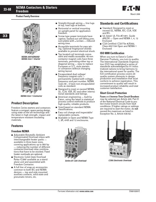
March 2009Product Family OverviewProduct DescriptionFreedom Series starters and contactors feature a compact, space-saving design, using state-of-the-art technology and the latest in high strength, impact and temperature resistant insulating materials.FeaturesFreedom NEMA■Adjustable Bimetallic AmbientCompensated Overload relays with interchangeable heater packs — available in three basic sizes,covering applications up to 900 hp — reducing the number of different contactor/overload relay combina-tions that have to be stocked. Fixed heater overloads are optional.■Electronic Solid-State Overload Relay (C396) available as a stand-alone unit and assembled with Freedom Contactor.■ A full line of snap-on accessories common to both IEC and NEMA devices — top and side mounted auxiliary contacts, solid-state and pneumatic timers, etc.■Straight-through wiring — line lugs at top, load lugs at bottom.■Horizontal or vertical mounting on upright panel for application freedom.■Screw type power terminals have captive, backed-out self-lifting pres-sure plates with ± screws — reduced wiring time.■Accessible terminals for easy wir-ing. Optional fingerproof shields available to prevent electrical shock.■Top located coil terminals conve-nient and readily accessible. 45 mm contactor magnet coils have three terminals, permitting either top or diagonal wiring — easy to replace European or U.S. style starters or contactors without changing wiring layout.■Encapsulated dual voltage/frequency magnet coils —permanently marked with voltage, frequency and part number. NEMA Sizes 00 – 0 have non-encapsulated coils as standard.■Designed to meet or exceed NEMA, UL, CSA, VDE, BS and other interna-tional standards and listings.■American engineering — built by Eaton, using the latest in statistical process control methods to produce high quality, reliable products.■Sized based on standard NEMA classifications.■Easy coil change and inspectable/replaceable contacts.■Available in Open and NEMA Type 1, 3R, 4/4X and 12 enclosures.Standards and Certifications■Standard: Designed to meet or exceed UL, NEMA, IEC, CSA, VDE and BS.■UL listed: UL File #E1491, Guide #NLDX — Open and NEMA 1, 4, 12 Enclosed■CSA Certified: CSA File #LR353, Class #321104 Open and NEMA 1 EnclosedISO 9000 CertificationWhen you turn to Eaton’s Cutler-Hammer Products, you turn to quality. The International Standards Organiza-tion (ISO) has established a series of standards acknowledged by 91 indus-trialized nations to bring harmony to the international quest for quality. The ISO certification process covers 20 quality system elements in design, production and installation that must conform to achieve registration. This commitment to quality will result in increased product reliability and total customer satisfaction.Short Circuit ProtectionFuses and Inverse-Time Circuit Breakers may be selected per Article 430, Part D of the National Electrical Code to pro-tect motor branch circuits from fault conditions. If higher ratings or settings are required to start the motor, do not exceed the maximum as listed in Exception No. 2, Article 430-52.NEMA AN16DN0AB NEMA Size 1 StarterNEMA Size 1 ContactorSeries B1 32A OverloadC396 Electronic OverloadMarch 2009Starters — 3-Phase Non-reversing and Reversing, Full VoltageContentsDescriptionPageProduct Family OverviewProduct Description. . . . . . 33-68Features . . . . . . . . . . . . . . . 33-68Standards andCertifications . . . . . . . . . . 33-68Catalog NumberSelection . . . . . . . . . . . . . 33-69Starters — 3-Phase Non-reversing and Reversing, Full Voltage, Bi-Metallic OverloadProduct Description. . . . . . 33-73Features . . . . . . . . . . . . . . . 33-73Technical Data . . . . . . . . . . 33-74Wiring Diagrams . . . . . . . . 33-74Product Selection. . . . . . . . 33-75Starters — 3-Phase Multispeed, Bi-Metallic OverloadProduct Selection. . . . . . . . 33-76Starters — Single-PhaseNon-reversing, Full Voltage, Bi-Metallic OverloadProduct Description. . . . . . 33-77Wiring Diagrams . . . . . . . . 33-77Product Selection. . . . . . . . 33-77Starters — 3-Phase Non-reversing and Reversing, Full Voltage,C386 Electronic Overload . . 33-78Technical Data . . . . . . . . . . . . . 33-79Accessories . . . . . . . . . . . . . . . 33-82Auxiliary Contacts . . . . . . . 33-86DC Magnet Coils . . . . . . . . 33-88Mounting Plates. . . . . . . . . 33-89Special Modifications . . . . . . . 33-90Renewal Parts . . . . . . . . . . . . 33-91Dimensions . . . . . . . . . . . . . . . 33-94Product DescriptionNon-reversingThree-phase, full voltage magnetic starters are most commonly used to switch AC motor loads. Starters con-sist of a magnetically actuated switch (contactor) and an overload relay assembled together.ReversingThree-phase, full voltage magnetic starters are used primarily for revers-ing of 3-phase squirrel cage motors. They consist of two contactors and a single overload relay assembledtogether. The contactors are mechani-cally and electrically interlocked to prevent line shorts and energization of both contactors simultaneously.Features■Bimetallic Ambient Compensated Overload relays — available in three basic sizes covering applications up to 900 hp — reducing number of different contactor/overload relay combinations that have to be stocked.These overload relays feature:❑Selectable Manual or Automatic Reset operation.❑Interchangeable heater packs adjustable ±24% to match motor FLA and calibrated for 1.0 and 1.15 service factors. Heater packs for smaller overload relay will mount in larger overload relay — useful in derating applications such as jogging.❑Load lugs built into relay base.❑Single-phase protection, Class 20 or Class 10 trip time.❑Overload trip indication.❑Electrically isolated NO-NC con-tacts (pull RESET button to test).■The C396 is a self-powered, robust electronic overload designed for integrate use with Freedom NEMA contactors.❑Tiered feature set to provide cov-erage specific to your application.❑Broad 5:1 FLA range for maxi-mum flexibility.❑Coverage from 0.05 – 1500 Amps to meet all your needs.■Long life twin break, silver cadmium oxide contacts — provide excellent conductivity and superior resistance to welding and arc erosion. Gener-ously sized for low resistance and cool operation.■Designed to 3,000,000 electrical operations at maximum hp ratings up through 25 hp at 600V.■Steel mounting plate standard on all open type starters.■Wired for separate or common control.Non-reversing■Holding circuit contact(s) supplied as standard:❑Sizes 00 – 3 have a NO auxiliary contact block mounted on right-hand side (on Size 00, contact occupies 4th power pole position — no increase in width).❑Sizes 4 – 5 have a NO contact block mounted on left side.❑Sizes 6 – 7 have a 2NO/2NC contact block on top left.❑Size 8 has a NO/NC contact block on top left back and a NO on top right back.Reversing■Each contactor (Size 00 – 8) supplied with one NO-NC sidemounted contact block as standard. NC contacts are wired as electrical interlocks.NEMA Size 1 — Cat. No. AN16DN0ABNEMA Size 1 — Cat. No. AN56DN0ABMarch 2009Starters — 3-Phase Non-reversing and Reversing, Full VoltageTechnical DataTable 33-96. Wire (75°C) Sizes — AWG or kcmil — NEMA Sizes 00 – 2 — Open and EnclosedᕃTwo compartment box lug.ᕄMinimum per NEC. Maximum wire size: Sizes 00 and 0 to 8 AWG and Sizes 1 – 2 to 2 AWG.Table 33-97. Wire (75°C) Sizes — AWG or kcmil — NEMA Sizes 3 – 8 — Open and EnclosedᕅMinimum per NEC. Maximum wire size: Sizes 00 and 0 to 8 AWG and Sizes 1 – 2 to 2 AWG.Wiring DiagramsFigure 33-24. Typical Wiring Diagrams — Three-Phase and Single-Phase ApplicationsNEMA SizeWire Size ᕄ Cu OnlyPower Terminals — Line0001212 – 16 AWG stranded, 12 – 14 AWG solid 8 – 16 AWG stranded, 10 – 14 AWG solid 8 – 14 AWG stranded or solid3 – 14 AWG (upper) and/or 6 – 14 AWG (lower) stranded or solid ᕃPower Terminals — Load — Cu Only (stranded or solid)00 – 01 – 214 – 6 AWG stranded or solid 14 – 2 AWG stranded or solidControl Terminals — Cu Only12 – 16 AWG stranded, 12 – 14 AWG solidNEMA SizeWire Size ᕅPower Terminals — Line and Load31/0 – 14 AWG Cu/Al4Open — 3/0 – 8 AWG Cu; Enclosed — 250 kcmil — 6 AWG Cu/Al 5678750 kcmil — 2 AWG; or (2) 250 kcmil — 3/0 AWG Cu/Al (2) 750 kcmil — 3/0 AWG Cu/Al (3) 750 kcmil — 3/0 AWG Cu/Al (4) 750 kcmil — 1/0 AWG Cu/AlControl Terminals — Cu Only12 – 16 AWG stranded, 12 – 14 AWG solidTable 33-98. Plugging and Jogging Service Horsepower Ratings ᕆᕆMaximum horsepower where operation is interrupted more than 5 times per minute, or more than 10 times in a 10 minute period. NEMA Standard ICS2-1993 table 2-4-3.Kits and Accessories■Auxiliary Contacts, contactor mounted — Pages 33-86 – 33-87. ■Transient Suppressor, for magnet coil — Pages 33-84.■Timers — Solid-State andPneumatic, mount on contactor — Page 33-83.Renewal Parts Publication Numbers■See Page 33-91.NEMA Size 200V 230V 460V 575V 000123—1-1/237-1/2151/21-1/2310201/22515301/2251530456256012530751506015030060150300March 2009Starters — 3-Phase Non-reversing and Reversing, Full Voltage, Bi-Metallic OverloadProduct SelectionWhen Ordering Supply■Catalog Number■Heater pack number (see selectiontable, Pages 33-107 – 33-108) or full load current.Table 33-99. Type AN16/AN56 NEMA — Manual or Automatic Reset Overload Relay — Non-reversing and ReversingNote: Starter Catalog Numbers do not include heater packs. Select one carton of three heater packs. Heater pack selection, Pages 33-107 – 33-108.ᕃUnderscore (_) indicates coil suffix required, see Table 33-100.ᕄMaximum horsepower rating of starters for 380V 50 Hz applications: ᕅThe service-limit current ratings represent the maximum rms current, in amperes, which the controller shall be permitted to carry for protracted periods in normal service. At service-limit current ratings, temperature rises shall be permitted to exceed those obtained by testing the controller at itscontinuous current rating. The current rating of overload relays or trip current of other motor protective devices used shall not exceed the service-limit current rating of the controller.ᕆCommon control. For separate 120V control, insert letter D in 7th position of listed Catalog Number. EXAMPLE: AN56VN D 0CB.Magnet Coils — AC or DCStarter coils listed in this section also have a 50 Hz rating as shown in the adjacent table. Select required starter by Catalog Number and replace the magnet coil alpha designation in the Catalog Number (_) with the proper Code Suffix from the adjacent table.For Sizes 00 – 2 and 5 – 8, the magnet coil alpha designation will be the next to last digit of the listed Catalog Num-ber. EXAMPLE: For a 380V, 50 Hz coil, change AN16BN0_C to AN16BN0L C. For all other sizes, the magnet coil alpha designation will be the last digit of the listed Catalog Number.For DC Magnet Coils , see Accessories, Pages 33-88 – 33-89.Table 33-100. AC Suffix CodeᕇNEMA Sizes 00 and 0 only.ᕈNEMA Sizes 00 and 0 only. Sizes 1 – 8 are 24/60 only.NEMA Size Continuous Ampere Rating Service-Limit CurrentRating ᕅ(Amperes)Maximum UL Horsepower ᕄ3-PoleNon-reversing ᕃ3-PoleReversing ᕃVerticalReversing ᕃPrice U.S. $1-Phase3-Phase115V 230V 208V 240V 480V 600V CatalogNumber Price U.S. $Catalog Number Catalog Number 009111/311-1/21-1/222AN16AN0_C AN56AN0_C —01821123355AN16BN0_C AN56BN0_C AN56BNV0_12732237-1/27-1/21010AN16DN0_B AN56DN0_B AN56DNV0_2455237-1/210152525AN16GN0_B AN56GN0_B AN56GNV0_390104——25305050AN16KN0_AN56KN0_AN56KNV0_4135156——4050100100AN16NN0_AN56NN0_AN56NNV0_5270311——75100200200AN16SN0_B AN56SN0_B —6540621——150200400400AN16TN0_C AN56TN0_C —7810932——200300600600AN16UN0_B AN56UN0_B —8 ᕆ12151400——400450900900AN16VN0_BAN56VN0_B—NEMA Size 00012345678Horsepower1-1/2510255075150300600900Size 0Non-reversing StarterSize 1Reversing StarterSize 3 Vertical Reversing StarterNEMA Size 0Cat. No. AN56BN0ACCoil Volts and Hertz Code Suffix 120/60 or 110/50240/60 or 220/50480/60 or 440/50600/60 or 550/50A B C D 208/60277/60208 – 240/60 ᕇ240/50E H J K 380 – 415/50550/5024/60, 24/50 ᕈ24/50L N T U 32/5048/6048/50V W YTechnical Data. . . . . . . . . . Pages 33-79 – 33-81Overload Relay . . . . . . . . . Page 33-103Dimensions . . . . . . . . . . . . Pages 33-96 – 33-98Special Modifications . . . Page 33-90Accessories. . . . . . . . . . . . Pages 33-82 – 33-90March 2009Starters — Single-Phase Non-reversing, Full Voltage, Bi-Metallic OverloadProduct DescriptionSingle-phase, full voltage magnetic starters connect the motor directly across the line, allowing it to draw full inrush current during start-up. These starters are most commonly used for control of self-starting single-phase motors up to 15 horsepower at 230V. They consist of a 2-pole electromag-netic contactor to make and break the motor power circuit and an overload relay to provide running overload protec-tion. Starters listed in the table include:■Two-pole Freedom Series contactor with long life twin break, silver cadmium oxide contacts. Generously sized for low resistance and cool operation. Designed to 3 mil-lion electrical operations at maximum hp and 30 million mechanical operations to Size 0, 10 million operations to Size 2 and 6 million operations to Size 3.■Three-pole Freedom Series overload with poles 2 and 3 wired in series for motor overload protection. This over-load is ambient compensated, selectable Manual or Auto-matic reset, interchangeable Class 10 or 20 heater packs, 1.0 or 1.15 service factor selectability, overload trip indica-tion and electrically isolated NO-NC contacts (pull RESET button to test).■Holding circuit NO auxiliary contact supplied as standard. On Size 00, the contact occupies the 4th power pole position. Sizes 0 – 3 have the NO auxiliary mounted on the right side of the contactor.■Steel mounting plate as standard on all open type starters. Wired for separate or common control.Wiring DiagramsFigure 33-25. Typical Wiring Diagrams — Single-Phase Applications (Factory Wired)Product SelectionWhen Ordering Specify■Catalog Number■Heater Pack Number (see selection table, Pages 33-107 – 33-108) or full load current.Table 33-104. Type BN16 NEMA — Manual or Automatic Reset Overload RelayNote: Starter Catalog Numbers do not include heater packs. Select 1 carton of 3 heater packs. Heater pack selection, Pages 33-107 – 33-108.ᕃFor separate 120V control circuit. For maximum hp at listed motor voltages, use the rating of other starters of same size.NEMA Size 1 — Cat. No. BN16DN0ABNEMA SizeMaximum Horsepower MagnetCoil Voltage (60 Hz)Open Type 2-Pole Motor Voltage 1-Phase Catalog Number Price U.S. $001152301/31120 ᕃ240BN16AN0AC BN16AN0BC 011523012120 ᕃ240BN16BN0AC BN16BN0BC 111523023120 ᕃ240BN16DN0AB BN16DN0BB 1P 11523035120 ᕃ240BN16PN0AB BN16PN0BB 211523037-1/2120 ᕃ240BN16GN0AB BN16GN0BB 31152307-1/215120 ᕃ240BN16KN0A BN16KN0BContentsDescriptionPage Thermal Overload RelaysProduct Description. . . . . . 33-103Features . . . . . . . . . . . . . . . 33-103Operation . . . . . . . . . . . . . . 33-103Technical Information . . . . 33-103Technical Data . . . . . . . . . . 33-104Factory Modifications . . . . 33-105Accessories. . . . . . . . . . . . . 33-105Replacement Parts. . . . . . . 33-105Dimensions. . . . . . . . . . . . . 33-106Product Selection. . . . . . . . 33-107Heater Pack Selection . . . .33-107Product DescriptionC306 Overload Relays are designed for use with CE or CN non-reversing and reversing contactors. Four sizes are available for overload protection up to 144A.Features■Selectable Manual or Automatic Reset operation.■Interchangeable Heater Packs adjustable ±24% to match motor FLA and calibrated for use with 1.0 and 1.15 service factor motors.Heater packs for 32A overload relay will mount in 75A overload relay — useful in derating applications such as jogging.■Class 10 or 20 heater packs.■Load lugs built into relay base.■Bimetallic, ambient compensated operated. Trip free mechanism.■Electrically isolated NO-NC contacts (pull RESET button to test).(Electrical Ratings see Table 33-158 on Page 33-104).■Shrouded or fingerproof terminals to reduce possibility of electrical shock.■Meets UL 508 single-phasing requirements.■UL listed, CSA certified, NEMA compliance and CE mark.OperationC306 Overload Relay SettingFigure 33-43. FLA Dial AdjustmentFor motors having a 1.15 service fac-tor, rotate the FLA adjustment dial to correspond to the motor’s FLA rating. Estimate the dial position when the motor FLA falls between two letter values as shown in the example.For motors having a 1.0 service factor, rotate the FLA dial one-half position counterclockwise (CCW).Figure 33-44. Manual/Automatic Reset The overload relay is factory set at M for manual reset operation. For auto-matic reset operation, turn the reset adjustment dial to the A position as shown in the illustration.Automatic reset is not intended for two-wire control devices.Test for Trip IndicationTo test overload relay for trip indica-tion when in manual reset, pull out the blue reset button. An orange flag will appear indicating that the device has tripped. Push reset button in to reset.Warning — To provide continued pro-tection against fire or shock hazard, the complete overload relay must be replaced if burnout of the heater element occurs.Technical InformationGeneral“Overload relays are provided to pro-tect motors, motor control apparatus and motor-branch circuit conductors against excessive heating due to motor overloads and failure to start. This definition does not include:1) motor circuits over 600V,2) short circuits,3) ground faults and 4) fire pump control.” (NEC Art. 430-31)Time Current CharacteristicsThe time-current characteristics of an overload relay is an expression of per-formance which defines its operating time at various multiples of its current setting. Tests are run at Underwriters Laboratories (UL) in accordance with NEMA Standards and the NEC. UL requires:■When tested at 100 percent of its current rating, the overload relay shall trip ultimately.■When tested at 200 percent of its current rating, the overload relay shall trip in not more than 8 minutes.■When tested at 600 percent of the current rating, the overload relay shall trip in not more than 10 or 20 seconds, depending on the Class of the relay.“Current Rating” is defined as the minimum current at which the relay will trip. Per NEC, an overload must ultimately trip at 125% of FLA current (heater) setting for a 1.15 service factor motor and 115% FLA for a 1.0 service factor motor.“Current Setting” is defined as the FLA (Full Load Amperes) of the motor and thus the overload heater pack setting.Example: 600% of current rating is defined as 750% (600 x 1.25) of FLA current (heater) setting for a 1.15 ser-vice factor motor. A 10A heater setting must trip in 20 seconds or less at 75A 32A OverloadCat. No. C306DN3BProduct SelectionTable 33-166. C306 Thermal Overload RelaysᕃNEMA Sizes 5 – 8 use the 32A overload in conjunction with CTs.ᕄSeries B overload relays have load lugs built into relay base and will only accept Series B heater packs. These relays can be directly attached to contactor or they can be DIN rail or panel mounted using adapter on Page 33-105.ᕅThese relays can be panel mounted only.Table 33-167. C306 Thermal Overload RelaysᕆOverload relay assembled with mounting adapter for DIN rail or panel mount.ᕇPanel mount only.ᕈNEMA Sizes 5 – 8 use the 32A overload in conjunction with CTs.Heater Pack SelectionHeater packs H2001B to H2017B and H2101B to H2117B are to be used only with Series B overload relays Catalog Numbers C306DN3B (Part No. 10-7016) and C306GN3B (Part No. 10-7020). The load lugs are built into the overload relay base to allow load wiring prior to heater pack installa-tion. The previous heater design had integral load lugs. The Series B heater packs are electrically equivalent to the previous heater design. Heaters H2018-3 to H2024-3 have not changed.Table 33-168. Starters with Series B Overload RelaysNote: The series of a starter is the last digit of the listed Catalog Number. EXAMPLE: AN16DN0A B .For Use with Freedom Series Contactors Maximum Ampere RatingNumber of PolesOpen Type NEMA 1 Enclosed NEMA Size Catalog NumberPrice U.S. $Catalog Number Price U.S. $00, 01, 2345 – 8 ᕃ32 ᕄ75 ᕄ105 ᕅ144 ᕅ—3333—C306DN3B C306GN3B C306KN3C306NN3—C306DG3B C306GG3B —75A OverloadCat. No. C306GN3B 75A OverloadCat. No. C306GT3B 32A OverloadCat. No. C306DT3B 32A OverloadCat. No. C306DN3BFor Stand-Alone Applications Maximum Ampere RatingNumber of PolesOpen Type NEMA Size Catalog NumberPrice U.S. $00, 0, 1 ᕆ1 ᕆ3 ᕇ4 ᕇ5 – 8 ᕈ3275105144—3333—C306DT3B C306GT3B C306KN3C306NN3—Heater PackH2001B – H2017BHeater PackH2101B – H2117BHeater Pack H2018 – H2024NEMA — AN Type IEC — AE Type Size Series Size Series 00 – 01 – 2567 – 8C B B C BA – F G – KC BTechnical Data . . . . . . . . Page 33-104Dimensions. . . . . . . . . . . . Page 33-106。
防爆型磁感应开关 KGE1-(1A)P 127V
防爆型磁感应开关 KGE1-(1A)P 127V
一、KGE1-1P矿用浇封型磁感应开关参数:
1、供电电源:110V 10%50HZ。
2、触点参数:2A127VAC。
3、触点个数:两组常开,常闭点。
4、速度响应:可以满足30M/S的速度要求。
5、工作次数:触点的机械寿命可以达到9万次。
防爆型磁感应开关 KGE1-1AP 127V应用广泛,和相应TS250,TS360,TS500永磁铁配合使用分别可以在250mm,360mm,500mm处感应到检测物体,KGE1-1P 系列磁开关可以完全取代进口的“蒂芬巴赫磁开关”和西门子“C25315-A39-A、C25315-A39-A2-3”磁开关。
KGE1-1P系列磁开关可以取代KG1010系列磁开关,同时可以取代KYCJ系列磁开关、CY系列磁开关、CJK系列磁开关、KSA系列磁开关,具有这些磁开关没有磁定向定位功能,是传统磁传感器革命性的进步!
二、KGE1-1AP矿用浇封型磁感应开关的类型及质量识别方法
KGE1-1P系列磁开关有两种类型:
1、第一种单极性:磁开关对磁铁的S极有作用,对N极没有作用,这种磁开关具有强大的抗干扰能力;同时单极性磁开关可以有效消除罐笼磁化后对磁开关的影响,这是双极性磁开关所无法实现的。
这种磁开关价格较高。
2、第二种是双极性:磁开关对磁铁的S,N极均有作用。
但是,对于罐笼被磁化的情况双极性磁开关就不能很好的使用,经常会造成对位不准,信号报错,使用户不能很好使用。
这种磁开关价格相对较低。
一般情况下单极性磁开关现场使用的比较广泛因为有强大的抗干扰能力,双极性磁开关应用的比较少,因为他容易受到罐笼磁化后的影响。
磁性开关说明

磁性开关的性能对比
磁性开关的选用
说明 序号 项目 有接点 1 无接点 2 3 用途 使用电压V 使用电压V 漏电流 无 3线式:100µA以下 线式:100 A 线式:1mA以下 2线式:1mA以下 动作时间ms 动作时间ms 1.2 ≤1 寿命 几千万次 半永久 适合高频工作 耐冲击性能m/s 耐冲击性能m/s2 300 500
磁性开关
本章要求掌握的主要内容: 本章要求掌握的主要内容:
1. 磁性开关的工作原理 2. 磁性开关的分类 3. 磁性开关的性能对比 4. 磁性开关的使用注意事项
磁性开关的工作原理
• 磁性开关是用来检测气缸活塞位置的: 磁性开关是用来检测气缸活塞位置的:即检测活塞的 运动行程的。它可分为有接点型和无接点型两种。 运动行程的。它可分为有接点型和无接点型两种。
磁性开关的使用注意事项
• 有接点磁性开关注意事项
ቤተ መጻሕፍቲ ባይዱ
1、安装时,不得让开关受过大的冲击力,如将开关打入、抛扔等, 、安装时,不得让开关受过大的冲击力,如将开关打入、抛扔等, 会损坏开关; 会损坏开关; 2、不能让磁性开关处于水或冷却液中使用; 、不能让磁性开关处于水或冷却液中使用; 3、绝对不要用于有爆炸性、可燃性气体的环境中; 、绝对不要用于有爆炸性、可燃性气体的环境中; 4、周围有强磁场、大电流(如电焊机等)的环境中应选用耐强磁场 、周围有强磁场、大电流(如电焊机等) 的磁性开关; 的磁性开关; 5、不要把连接导线和动力线(如电动机等)、高压线并在一起; 、不要把连接导线和动力线(如电动机等)、高压线并在一起; )、高压线并在一起
无接点电晶体型- 无接点电晶体型-抗强磁型
• 抗交流磁场型
CS1-69AM 磁感 应开关
只能用于直流电源,专用于 系列焊接夹紧缸; 只能用于直流电源,专用于MCK系列焊接夹紧缸; 系列焊接夹紧缸 目前我司暂未有抗直流强磁场型磁性开关。 目前我司暂未有抗直流强磁场型磁性开关。
KGE1系列磁性开关使用说明书

KGE1系列磁性开关使用说明书索引一、原理 (1)二、产品型号规格和结构 (3)三、主要技术参数 (6)四、永磁铁磁场源使用方法 (9)五、钢丝绳磁场源使用方法 (11)六、使用注意事项 (13)七、附图 (14)使用本产品之前,请仔细阅读全部说明,它会帮你解决许多问题。
一原理KGE1系列磁性开关,由湖北杭荣电气公司所研制,用于矿井单绳和多绳提升机作井筒开关,也适用于其他机械设备作磁性接近开关。
KGE1系列磁性开关是非机械接触式磁性接近开关。
它由磁传感器和电子电路及输出开关组成。
当磁性检测体永磁铁进入KGE1开关磁传感器的感应区域,靠磁场作用,KGE1开关动作,输出开关信号。
输出信号反映检测体的位置、运动方向,作控制系统的行程控制信号。
KGE1系列磁性开关有通用型和防爆型两类、四种型号产品:KGE1-1型磁性开关;KGE1-2型磁性开关;KGE1-3型和KGE1-4型保持式磁性开关。
KGE1-1型磁性开关,当外界S极磁场作用于磁传感器时,开关动作,转换2秒。
静止作用时,处于转换状态,失去磁场作用,自动复位。
类似一般机械式瞬时动作型按钮开关,按压转换,释放则自动复位。
故又称其为磁性按钮开关。
KGE1-2型磁性开关,能识别磁场运动方向。
磁传感器检测到外界作用磁场N-S极方向磁场过零时,开关动作,转换2秒。
静止该过零点时,处于转换状态,失去外界磁场作用,自动复位。
S-N极方向磁场过零不转换。
KGE1-3和KGE1-4型保持式磁性开关,其作用磁场形式不同。
KGE1-3型保持式磁性开关有两个状态,能保持。
当外界S极磁场自下而上作用于磁传感器时,开关转换动触点与上端接通,指示红灯亮,此状态被保持。
即使失去外界磁场作用、开关失电、上电,仍保持此状态。
当外界有S极磁场自上而下作用于磁传感器时,转换动触点与下端接通,指示绿灯亮,并一直保持这种状态。
直至下次自下而上动作。
S极磁场上下拨动3型磁开关,磁开关又能保持各个状态,类似用力上下拨动机械式钮子开关一下,又称其为磁性钮子开关。
卡莫齐系列K电磁阀产品说明书
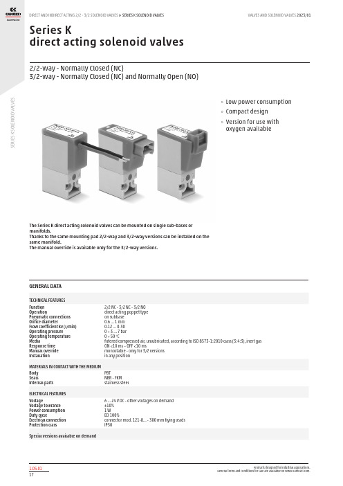
S E R I E S K S O L E N O I D V A L V E SSeries Kdirect acting solenoid valves2/2-way - Normally Closed (NC)3/2-way - Normally Closed (NC) and Normally Open (NO)The Series K direct acting solenoid valves can be mounted on single sub-bases or manifolds.Thanks to the same mounting pad 2/2-way and 3/2-way versions can be installed on the same manifold.The manual override is available only for the 3/2-way versions.»Low power consumption »Compact design »Version for use with oxygen availableGENERAL DATATECHNICAL FEATURES Function OperationPneumatic connections Orifice diameterFlow coefficient kv (l/min) Operating pressure Operating temperature MediaResponse time Manual override Installation2/2 NC - 3/2 NC - 3/2 NO direct acting poppet type on subbase 0.6 ... 1 mm 0.12 ... 0.30 0 ÷ 3 ... 7 bar 0 ÷ 50 °Cfiltered compressed air, unlubricated, according to ISO 8573-1:2010 class [3:4:3], inert gas ON <10 ms – OFF <10 msmonostable - only for 3/2 versions in any positionMATERIALS IN CONTACT WITH THE MEDIUM Body SealsInternal parts PBTNBR - FKM stainless steelELECTRICAL FEATURES VoltageVoltage tolerance Power consumption Duty cycleElectrical connection Protection class6 ... 24 V DC - other voltages on demand ±10% 1 WED 100%connector mod. 121-8... - 300 mm flying leads IP50Special versions available on demandS E R I E S K S O L E N O I D V A L V E SCODING EXAMPLES E R I E S K S O L E N O I D V A L V E Sor2x M1.6x16 screws for mounting on metal* add - VOLTAGE(see CODING EXAMPLE)Series K solenoid valve - 2/2-way NC - in-line connectorSupplied with: 1x interface seal2x Ø1.6x16 screws for mounting on plastic or2x M1.6x16 screws for mounting on metal)* add - VOLTAGE(see CODING EXAMPLE)Series K solenoid valve - 2/2-way NC - 300 mm flying leadsSupplied with: 1x interface seal2x Ø1.6x16 screws for mounting on plastic or2x M1.6x16 screws for mounting on metalS E R I E S K S O L E N O I D V A L V E Sor2x M1.6x16 screws for mounting on metal* add - VOLTAGE(see CODING EXAMPLE)Series K solenoid valve - 3/2-way NC - in-line connectorSupplied with: 1x interface seal2x Ø1.6x16 screws for mounting on plastic or2x M1.6x16 screws for mounting on metal* add - VOLTAGE(see CODING EXAMPLE)Series K solenoid valve - 3/2-way NC - 300 mm flying leadsSupplied with: 1x interface seal2x Ø1.6x16 screws for mounting on plastic or2x M1.6x16 screws for mounting on metalS E R I E S K S O L E N O I D V A L V E S2x Ø1.6x19 screws for mounting on plastic or2x M1.6x19 screws for mounting on metalFor use without port 1 and 3 inversion interface, use16 mm long screws (see accessories)* add - VOLTAGE(see CODING EXAMPLE)Series K solenoid valve - 3/2-way NO - in-line connectorSupplied with:1x interface for NO with position ports as per NC 2x interface seals2x Ø1.6x19 screws for mounting on plastic or2x M1.6x19 screws for mounting on metalFor use without port 1 and 3 inversion interface, use16 mm long screws (see accessories)* add - VOLTAGE(see CODING EXAMPLE)Series K solenoid valve - 3/2-way NO - 300 mm flying leadsSupplied with:1x interface for NO with position ports as per NC 2x interface seals2x Ø1.6x19 screws for mounting on plastic or2x M1.6x19 screws for mounting on metalFor use without port 1 and 3 inversion interface, use16 mm long screws (see accessories)S E R I E S K S O LE N O IDV A L V E SSingle sub-base for solenoid valve size 10 mmSingle sub-base suitable for Series K 2-way or 3-way solenoid valveUse solenoid valves with screws for mounting on metal (see coding)Material: anodized aluminium Connections: M5 threadsManifold Mod. K1**-02** Number of positionsWith side outlets and conveyed inlet and exhaust. Use solenoid valves with screws for mounting on metal (see coding)Material: anodized aluminiumConnections: M5 threadsPosition valve capSupplied with:1x position valve cap 3x O-Rings2x M1.6x6 screws for mounting on metalS E R I E S K S O L E N O I D V A L V ESMounting screws for Series K solenoid valves16 mm long screws for use with Series K 3/2-way NO solenoid valves without port 1 and 3 inversioninterfaceConnector with flying leads Mod. 121-8..。
ABB 1G 单向开关产品说明书
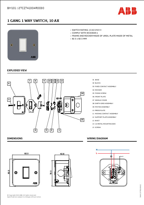
EXPLODED VIEW• SWITCH RATING: 10 AX 250 V~• COMPLY WITH IEC60669-1• FRAME AND ROCKER MADE OF UREA, PLATE MADE OF METAL • 82.5 x 82.5 MM01 BASE 02 BLOCK03 FIXED CONTACT ASSEMBLY 04 ROCKER05 FIXING SCREW 06 FRONT PLATE 07 MIDDLE COVER08 EARTH GRID ASSEMBLY 09 PISTON ASSEMBLY 10 PRESS PLATE11 MOVING CONTACT ASSEMBLY12 SUPPORT PLATE ASSEMBLY 13 RIVET14 1G METAL MOUNTING BOX 15 SCREWEXPLODED VIEWDIMENSIONS WIRING DIAGRAM• SWITCH RATING: 10 AX 250 V~• COMPLY WITH IEC60669-1• FRAME AND ROCKER MADE OF UREA, PLATE MADE OF METAL • 82.5 x 82.5 MMEXPLODED VIEWDIMENSIONS WIRING DIAGRAM01 BASE 02 BLOCK03 FIXED CONTACT ASSEMBLY04 ROCKER 05 FIXING SCREW 06 FRONT PLATE 07 MIDDLE COVER08 EARTH GRID ASSEMBLY 09 PISTON ASSEMBLY 10 PRESS PLATE11 MOVING CONTACT ASSEMBLY 12 SUPPORT PLATE ASSEMBLY13 RIVET14 1G METAL MOUNTING BOX 15 SCREW• SWITCH RATING: 10 AX 250 V~• COMPLY WITH IEC60669-1• FRAME AND ROCKER MADE OF UREA, PLATE MADE OF METAL • 82.5 x 82.5 MM01 BASE02 FIXED CONTACT ASSEMBLY 03 ROCKER 04 FIXING SCREW05 FRONT PLATE 06 MIDDLE COVER 07 EARTH GRID ASSEMBLY 08 PISTON ASSEMBLY 09 PRESS PLATE10 MOVING CONTACT ASSEMBLY 11 SUPPORT PLATE ASSEMBLY 12 RIVET13 1G METAL MOUNTING BOX 14 SCREWEXPLODED VIEWDIMENSIONS WIRING DIAGRAM• SWITCH RATING: 10 AX 250 V~• COMPLY WITH IEC60669-1• FRAME AND ROCKER MADE OF UREA, PLATE MADE OF METAL • 82.5 x 82.5 MMEXPLODED VIEWDIMENSIONS WIRING DIAGRAM01 BASE02 FIXED CONTACT ASSEMBLY 03 ROCKER04 FIXING SCREW 05 FRONT PLATE 06 MIDDLE COVER 07 EARTH GRID ASSEMBLY 08 PISTON ASSEMBLY 09 PRESS PLATE10 MOVING CONTACT ASSEMBLY 11 SUPPORT PLATE ASSEMBLY 12 RIVET13 1G METAL MOUNTING BOX 14 SCREW• SWITCH RATING: 10 AX 250 V~• COMPLY WITH IEC60669-1• FRAME AND ROCKER MADE OF UREA, PLATE MADE OF METAL • 82.5 x 82.5 MMEXPLODED VIEWDIMENSIONS WIRING DIAGRAM01 BASE02 FIXED CONTACT ASSEMBLY 03 ROCKER 04 FIXING SCREW05 FRONT PLATE 06 MIDDLE COVER 07 EARTH GRID ASSEMBLY 08 PISTON ASSEMBLY 09 PRESS PLATE10 MOVING CONTACT ASSEMBLY 11 SUPPORT PLATE ASSEMBLY12 RIVET13 1G METAL MOUNTING BOX 14 SCREW• SWITCH RATING: 10 AX 250 V~• COMPLY WITH IEC60669-1• FRAME AND ROCKER MADE OF UREA, PLATE MADE OF METAL • 82.5 x 82.5 MM01 EARTH GRID ASSEMBLY 02 SUPPORT PLATE ASSEMBLY 03 FIXED CONTACT ASSEMBLY L104 PISTON ASSEMBLY 05 ROCKER 06 FIXING SCREW07 RIVET 08 FRONT PLATE 09 MIDDLE COVER 10 PRESS COVER11 FIXED CONTACT ASSEMBLY L212 MOVING CONTACT ASSEMBLY 13 BASE 14 SCREW15 1G METAL MOUNTING BOX1 GANG INTERMEDIATE SWITCH, 10 AXEXPLODED VIEWDIMENSIONS WIRING DIAGRAM• FLEX OUTLET RATING: 20 A 250 V~• COMPLY WITH BS 5733• FRAME MADE OF UREA, PLATE MADE OF METAL • 82.5 x 82.5 MM01 EARTH GRID02 EARTH TERMINAL ASSEMBLY 03 MIDDLE COVER04 FIXING SCREW 05 FRONT PLATE 06 GASKET 07 PRESS STRIP 08 SCREW09 CONNECTION PLATE L 10 RIVET11 1G METAL MOUNTING BOX 12 SCREW20 A CONNECTION UNIT WITH FLEX OUTLETEXPLODED VIEWDIMENSIONS WIRING DIAGRAM• SWITCH RATING: 20 A 250 V~• COMPLY WITH IEC60669-1• FRAME AND ROCKER MADE OF UREA, PLATE MADE OF METAL • 82.5 x 82.5 MM01 SCREW02 TERMINAL ASSEMBLY 03 FIXED CONTACTASSEMBLY L 04 MOVING CONTACTASSEMBLY05 SUPPORT PLATEASSEMBLY 06 FRONT PLATE 07 ROCKER08 FIXING SCREW 09 RIVET10 PISTON ASSEMBLY 11 LIGHT COVER 12 NEON ASSEMBLY 13 MIDDLE COVER14 SUPPORT PLATE N1 GANG DP SWITCH WITH NEON, 20 AEXPLODED VIEWDIMENSIONS WIRING DIAGRAM15 FIXED CONTACTASSEMBLY N 16 BASE 17 EARTH GRID 18 1G METALMOUNTING BOX• SWITCH RATING: 45 A 250 V~• COMPLY WITH IEC60669-1• FRAME AND ROCKER MADE OF UREA, PLATE MADE OF METAL • 82.5 x 143.5 MM01 SCREW02 EARTH GRID ASSEMBLY 03 FIXED CONTACTASSEMBLY L 04 MOVING CONTACTASSEMBLY05 SUPPORT PLATEASSEMBLY L 06 PISTON ASSEMBLY 07 RIVET08 FIXING SCREW 09 LIGHT COVER 10 FRONT PLATE 11 MIDDLE COVER 12 NEON ASSEMBLY 13 ROCKER14 SUPPORT PLATE N1 GANG 45 A DP Switch w/Neon (6 x 3)EXPLODED VIEWDIMENSIONS WIRING DIAGRAM15 FIXED CONTACTASSEMBLY N 16 BASE17 2G METALMOUNTING BOX• SOCKET RATING: 15 A 250 V~• COMPLY WITH BS 546• FRAME AND ROCKER ARE MADE OF UREA, PLATE IS MADE OF METAL• 82.5 x 82.5 MM01 EARTH GRID ASSEMBLY 02 SCREW03 SUPPORT PLATE L 04 FIXED CONTACTASSEMBLY L 05 CONTACT06 SHUTTER SPRING 07 MIDDLE COVER 08 RIVET09 FIXING SCREW 10 FRONT PLATE 11 ROCKER12 PISTON ASSEMBLY 13 SHUTTER14 MOVING CONTACTASSEMBLY15 CONNECTION PLATE N1 GANG 15 A SWITCHED SO SPEXPLODED VIEWDIMENSIONS WIRING DIAGRAM16 TERMINALASSEMBLY 17 BASE18 1G METALMOUNTING BOX•SOCKET RATING: 13 A 250 V~•COMPLY WITH IEC60884-1, IEC60884-2-3, BS1363-2•FRAME AND ROCKER ARE MADE OF UREA, PLATE IS MADE OF METAL•82.5 x 82.5 MM01 SCREW02 SUPPORT PLATE N 03 SUPPORT PLATE L 04 PLASTIC BLOCK05 L CONTACT ASSEMBLY 06 SHUTTER SPRING07 NEON ASSEMBLY08 LIGHT COVER 09 FRONT PLATE10 FIXING SCREW 11 RIVET12 MIDDLE COVER13 ROCKER14 PISTON ASSEMBLY 15 SHUTTER16 N CONTACT ASSEMBLYEXPLODED VIEWDIMENSIONS WIRING DIAGRAM17 MOVING CANTACTASSEMBLY 18 TERMINALASSEMBLY 19 BASE 20 EARTH GRIDASSEMBLY 21 1G METALMOUNTING BOX• SOCKET RATING: 13 A 250 V~• COMPLY WITH IEC60884-1, IEC60884-2-3, BS1363-2• FRAME AND ROCKER ARE MADE OF UREA, PLATE IS MADE OF METAL• 82.5 x 143.5 MM01 EARTH GRID ASSEMBLY 02 SCREW03 SUPPORT PLATE L 04 TERMINAL ASSEMBLY 05 L CONTACT ASSEMBLY 206 N CONTACT ASSEMBLY 207 SHUTTER SPRING 08 NEON ASSEMBLY 09 LIGHT COVER10 RIVET11 FIXING SCREW12 FRONT PLATE 13 MIDDLE COVER 14 ROCKER 15 ROCKER16 PISTON ASSEMBLYEXPLODED VIEWDIMENSIONS WIRING DIAGRAM17 SHUTTER 18 PLASTIC BLOCK 19 N CONTACTASSEMBLY 120 L CONTACTASSEMBLY 121 MOVING CANTACTASSEMBLY 22 SUPPORT PLATE N 23 BASE24 2G METALMOUNTING BOX• SUITABLE FOR RJ45 CAT.6 CABLE • COMPLY WITH BS 5733• FRAME MADE OF ABS, PLATE MADE OF METAL,SHUTTER MADE OF PC• 82.5 x 82.5 MM01 EARTH GRID ASSEMBLY 02 RJ45 CAT.6 MODULAR 03 SHUTTER 04 FIXING SCREW 05 RIVET06 FRONT PLATE 07 MIDDLE COVER 08 SPRING09 CAT COVER10 1G METAL MOUNTING BOXEXPLODED VIEWDIMENSIONS WIRING DIAGRAM• SUITABLE FOR RJ45 CAT.6 CABLE • COMPLY WITH BS 5733• FRAME MADE OF ABS, PLATE MADE OF METAL,SHUTTER MADE OF PC• 82.5 x 82.5 MM01 RJ45 CAT.6 MODULAR 02 EARTH GRID ASSEMBLY 03 SHUTTER 04 FIXING SCREW 05 RIVET 06 FRONT PLATE07 MIDDLE COVER 08 SPRING 09 CAT COVER10 1G METAL MOUNTING BOXEXPLODED VIEWDIMENSIONS WIRING DIAGRAM• SWITCH RATING: 10 A 250 V~• COMPLY WITH IEC60669-1• FRAME AND ROCKER MADE OF UREA, PLATE MADE OF METAL • 82.5 x 82.5 MM01 BASE 02 BLOCK03 FIXED CONTACTASSEMBLY04 SPRING 05 ROCKER 06 FIXING SCREW 07 FRONT PLATE 08 MIDDLE COVER09 EARTH GRID ASSEMBLY 10 PISTON ASSEMBLY 11 PRESS PLATE12 MOVING CONTACTASSEMBLY 13 SUPPORT PLATEASSEMBLY14 RIVET1 GANG 1 WAY PUSH BUTTON SWITCH, 10 AEXPLODED VIEWDIMENSIONS WIRING DIAGRAM15 1G METALMOUNTING BOX 16 SCREW• BLANK PLATE• COMPLY WITH BS 5733• PLATE MADE OF METAL • 82.5 x 82.5 MM01 EARTH GRID ASSEMBLY 02 FIXING SCREW 03 FRONT PLATE 04 RIVET05 1G METAL MOUNTINGBOXEXPLODED VIEWDIMENSIONS WIRING DIAGRAM• BLANK PLATE• COMPLY WITH BS 5733• PLATE MADE OF METAL • 143.5 x 82.5 MM01 EARTH GRID ASSEMBLY 02 FIXING SCREW 03 FRONT PLATE 04 RIVET05 2G METAL MOUNTINGBOXEXPLODED VIEWDIMENSIONS WIRING DIAGRAM• FCU RATING: 13 A 250 V~• COMPLY WITH BS 1363-4• FRAME MADE OF UREA, PLATE MADE OF METAL • 82.5 x 82.5 MM01 BASE 02 CONTACT 03 FIXING SCREW 04 PRESS STRIP 05 CABLE HOLDER 06 FUSE COVER 07 FUSE08 PLASTIC BLOCK 09 FRONT PLATE 10 LIGHT COVER 11 MIDDLE COVER12 ROCKER13 PISTON ASSEMBLY 14 TERMINAL ASSEMBLY 15 SUPPORT PLATE N16 SUPPORT PLATE L1 GANG 13 A SWITCHED FUSED CONNECTION UNIT W/NEONEXPLODED VIEWDIMENSIONS WIRING DIAGRAM17 MOVING CANTACTASSEMBLY 18 STATIC CONTACTASSEMBLY N 19 STATIC CONTACTASSEMBLY L 20 CONNECTION PLATE L 21 EARTH GRIDASSEMBLY 22 RIVET23 1G METALMOUNTING BOX 24 SCREW• CAVITY BOX• COMPLY WITH BS 5733• BOX MADE OF METAL • 78.5 x 78.5 MM01 FIXING SCREW 02 1G METAL MOUNTINGBOX1G METAL MOUNTING BOXEXPLODED VIEWDIMENSIONS WIRING DIAGRAM• CAVITY BOX• COMPLY WITH BS 5733• BOX MADE OF METAL • 139 x 78.5 MM01 FIXING SCREW 02 2G METAL MOUNTINGBOX2G METAL MOUNTING BOXEXPLODED VIEWDIMENSIONSWIRING DIAGRAM• FUSED RATING: 13 A 250 V~• COMPLY WITH BS1363-4• FRAME AND ROCKER MADE OF UREA, PLATE MADE OF METAL • 82.5 x 82.5 MM1G 13 A FUSED CONNECTION UNIT W/NEONEXPLODED VIEWDIMENSIONS WIRING DIAGRAM01 BASE02 CONNECTION PLATE L103 CONNECTION PLATE L204 SCREW 05 PRESS STRIP 06 CABLE HOLDER 07 PLASTIC BLOCK 08 MIDDLE COVER 09 FIXING SCREW 10 FRONT PLATE 11 LIGHT COVER12 NEON ASSEMBLY 13 FUSE COVER 14 FUSE15 CONNECTION PLATE N16 CONTACT17 TERMINALASSEMBLY 18 EARTH GRIDASSEMBLY 19 RIVET20 1G METALMOUNTING BOX 21 SCREW。
- 1、下载文档前请自行甄别文档内容的完整性,平台不提供额外的编辑、内容补充、找答案等附加服务。
- 2、"仅部分预览"的文档,不可在线预览部分如存在完整性等问题,可反馈申请退款(可完整预览的文档不适用该条件!)。
- 3、如文档侵犯您的权益,请联系客服反馈,我们会尽快为您处理(人工客服工作时间:9:00-18:30)。
KGE1系列磁性开关使用说明书索引一、原理 (1)二、产品型号规格和结构 (3)三、主要技术参数 (6)四、永磁铁磁场源使用方法 (9)五、钢丝绳磁场源使用方法 (11)六、使用注意事项 (13)七、附图 (14)使用本产品之前,请仔细阅读全部说明,它会帮你解决许多问题。
一原理KGE1系列磁性开关,由湖北杭荣电气公司所研制,用于矿井单绳和多绳提升机作井筒开关,也适用于其他机械设备作磁性接近开关。
KGE1系列磁性开关是非机械接触式磁性接近开关。
它由磁传感器和电子电路及输出开关组成。
当磁性检测体永磁铁进入KGE1开关磁传感器的感应区域,靠磁场作用,KGE1开关动作,输出开关信号。
输出信号反映检测体的位置、运动方向,作控制系统的行程控制信号。
KGE1系列磁性开关有通用型和防爆型两类、四种型号产品:KGE1-1型磁性开关;KGE1-2型磁性开关;KGE1-3型和KGE1-4型保持式磁性开关。
KGE1-1型磁性开关,当外界S极磁场作用于磁传感器时,开关动作,转换2秒。
静止作用时,处于转换状态,失去磁场作用,自动复位。
类似一般机械式瞬时动作型按钮开关,按压转换,释放则自动复位。
故又称其为磁性按钮开关。
KGE1-2型磁性开关,能识别磁场运动方向。
磁传感器检测到外界作用磁场N-S极方向磁场过零时,开关动作,转换2秒。
静止该过零点时,处于转换状态,失去外界磁场作用,自动复位。
S-N极方向磁场过零不转换。
KGE1-3和KGE1-4型保持式磁性开关,其作用磁场形式不同。
KGE1-3型保持式磁性开关有两个状态,能保持。
当外界S极磁场自下而上作用于磁传感器时,开关转换动触点与上端接通,指示红灯亮,此状态被保持。
即使失去外界磁场作用、开关失电、上电,仍保持此状态。
当外界有S极磁场自上而下作用于磁传感器时,转换动触点与下端接通,指示绿灯亮,并一直保持这种状态。
直至下次自下而上动作。
S极磁场上下拨动3型磁开关,磁开关又能保持各个状态,类似用力上下拨动机械式钮子开关一下,又称其为磁性钮子开关。
1 KGE1-4型保持式磁性开关,无论方向自上而下或自下而上,磁传感器检测到外界作用磁场N-S极方向磁场过零时,开关转换动触点与上端接通,指示红灯亮,此状态被保持。
当外界作用磁场S-N极方向磁场过零时,开关转换动触点与下端接通,指示绿灯亮,并一直保持这种状态。
KGE1-4型磁性开关在磁场过零点上下转换,具有准确的窄窗孔磁场过零转换特性,定位精度高。
KGE1磁性开关原理框图1。
它们使用了先进灵敏的磁传感器和微电子器件,具有高的磁灵敏度、高的分辨率和宽的反应频率。
电路设计采用了冗余结构和高抗干扰技术。
全部电路由环氧树脂固化在铝或铜开关壳内,全密封、防水、抗砸。
KGE1磁性开关由于综合采用了一系列先进设计和工艺技术,所以取得了较高的技术指标和性能,适用于各种矿井。
能在矿井井筒中不同维修,安全可靠的工作。
图1 KGE1磁性开关原理框图在矿井单绳和多绳提升机上使用KGE1磁性开关有两种方法:永磁铁磁场源法和钢丝绳磁场源法。
这两种用法都是直接检测提升容器实际所处位置。
可以同时使用这两种方法,配合电气控制设备,保障提升机安全准确动作。
本说明主要介绍这两种使用方法。
2二产品型号规格和结构KGE1系列磁性开关产品型号规格表1KGE1系列磁性开关产品外形如图2所示。
磁性开关全部电路由环氧树脂固化在开关壳内。
通用型磁开关为铝外壳,防爆型磁开关为铜外壳。
磁性传感器装在开关壳的端面内,开关的端面中心为磁检测准点。
由开关壳底部引出一根两米长十芯电缆,电缆芯线由十种颜色标记。
开关壳一侧面装有铭牌,名牌上标有出线图如图3所示。
使用时照图接线即可。
开关壳另一侧面装有两个发光二极管,分别显示电源和开关状况;开关转换时亮。
3型和4型磁开关的两个红绿发光二极管,分别显示开关输出转换触点的通断状态;红色发光二极管亮表示动触点与上端接通,绿色发光二极管亮表示动触点与下端接通。
开关安装面开孔尺寸如图2。
附图印有1:1开孔图。
安装磁开关时,请复印下来贴于固定支架上,以便于钻孔。
开关壳电缆出线孔旁还有一接地螺栓,安装时请牢固接好地线。
3图3 出线图使用产品时请先认证铭牌上的名称、型号、电源电压和出线图。
产品订货时请按名称-型号-电源电压注明,例如:通用型磁性开关KGE1——1P——220V防爆型保持式磁性开关KGE1——4T——127V4与KGE1系列磁性开关配套的还有如下产品:(1)TS型和TNS型专用永磁铁它们外形如图4所示。
永磁铁嵌套在铸铝外壳内。
TS型永磁铁凸出面为S极,安装平面为N极。
TNS型永磁铁两个固定孔方向分别为N极和S极。
正常使用情况下,永磁铁寿命可达十年以上。
永磁铁与KGE1系列磁性开关配套选用如表2,转换特性曲线如图5所示。
永磁铁型号及KGE1磁性开关配套选用表2图4 专用永磁铁(2)ES2000密封热缩管,150mm/根。
用于密封电缆线接头。
(3)GCC-1型钢丝绳充磁机。
(4)GXC-1型钢丝绳消磁机。
5三主要技术参数表36图5 转换特性曲线(重复误差小于5mm )7KGE1系列磁性开关特性一览表表4注:“●”表示具有特性、配套组合8四永磁铁磁场源使用方法这种用法如图6所示。
把永磁铁固定在提升容器(罐笼或机斗)侧壁上。
磁性开关安装在井筒抽罐道梁、井架等定点位置上,使开关端面对着永磁铁上下运行轨道空间。
提升过程中,容器上的磁铁到达磁性开关位置时,开关转换,发出减速、停车等位置信号。
9这种用法磁场源是永磁铁,其作为动件,磁性开关作为静件。
和机械式磁撞开关相类似,但无机械接触,而是靠磁场作用。
一般使用是,在提升容器上装一块永磁铁,一个定点位置安装一台磁开关。
使用多个磁开关可以得到准确的多点位置信号。
如果安装使用保持式磁性开关,由于保持式磁性开关具有位置记忆功能,通过PC查询它们的状态,立即可知提升容器实际所处井筒的区域。
使用十分方便。
永磁铁的选用请详见表2。
根据永磁铁与磁开关间的安装距离,选用相应型号永磁铁。
要求不可越档或跨档用大距离永磁铁。
因为磁开关的磁场灵敏度是一定的,安装距离越大,所用的永磁铁磁场强度也就越大。
越档或跨档用大距离永磁铁,不必要的强磁场会造成磁污染,而使磁开关误动作。
按表2配用,能保证磁开关正常可靠工作。
根据磁开关的方向性,2型、3型和4型磁开关安装底面的长边、TNS型永磁铁的N、S极应沿运行方向平行安装。
比如在竖井中,2型、3型和4型磁开关出线孔朝下安装,TNS型永磁铁N、S极上下安装。
在井口以下位置安装使用磁性开关时,开关上部应装防护板,避免重物砸掉开关。
要磁开关定位准确,开关固定支架应开双滑槽。
滑槽宽9mm,间距40mm,槽长等于行程。
调整如下:提升容器定位停定,安装好永磁铁。
磁开关顺滑槽逆运行方向靠向永磁铁,开关转换时固定紧即可。
在要求防爆的现场,请选用防爆型磁性开关。
一般矿井井筒中都比较潮湿,许多井筒还存在水淋现象。
KGE1系列磁性开关全部电路都用环氧树脂密封,完全适合在这样的环境下使用。
但电缆接头应采取密封措施。
建议使用ES 2000密封热缩管。
用一根长150mm ES 2000热缩管,套在电缆芯线接头中间位置,用煤气灯火焰加热。
温度超过135℃,其外层直径收缩挤压芯线,内层热溶胶熔化且流动,形成密封结构。
操作简便,效果极佳。
10五钢丝绳磁场源使用方法这种用法配套使用钢丝绳充磁机和消磁机。
先选择提升机钢丝绳摆动较小的地方,如滚筒、导向轮或天轮下方。
把磁性开关安装在钢丝绳旁边,使开关端面对着钢丝绳,端面距绳小于50mm。
然后用钢丝绳充磁机在钢丝绳定点位置上充磁,使该点局部磁化。
提升运行过程中,钢丝绳磁化段运行到达开关位置时,开关动作,发出减速等位置信号。
其原理类似磁带录放机;把位置信号录在钢丝绳上,运行中磁开关检测录磁点,发出位置信号。
使用KGE1-1型磁性开关,在一根钢丝绳上一个定点位充磁,上下运行时,开关都转换发信号。
信号继电线路要用方向选择和自保线路,如图7。
要发出上下运行位置信号,必须用二台KGE1-1型磁开关,分别装在二根钢丝绳旁。
使用KGE1-3型磁性开关,要求开关安装底面的长边与钢丝绳平等安装。
也要用二台开关分别装在二根钢丝绳旁,发出上下位置信号。
由于3型磁开关具有位置记忆功能,所以信号继电线路简单,只须方向选择即可,如图7。
图7是用KGE1磁性开关输出常开触点为例,画的正向运行信号继电线路,供参考。
图中Z是正向继电器触点,J1是1型磁开关的信号继电器,其他类推。
右表表示各型磁开关信号线路特性。
图7线路也适用于永磁铁磁场源使用方法。
11使用KGE1-2型磁性开关,可在一根钢丝绳两个位置点充磁。
上下运行时,2型磁开关N-S极方向磁场过零动作,发出上下位置信号,如图8所示。
一台2型磁开关相当于两台1型磁开关的功能。
信号继电线路简单,无需方向选择,只要自保线路即可,如图7。
KGE1-2型磁开关的安装和对钢丝绳的充磁要求如下:安装——KGE1-2型开关安装底面的长边与钢丝绳平行。
在竖井中使开关出线孔朝下安装。
充磁——从图7中要以看出,上行位置,在钢丝绳上充出一对磁极,N极在上,S极在下。
用充磁机N极在下,S极在上,卡住钢丝绳充磁即可。
下行位置正相反。
钢丝绳磁场源法磁性开关放在井上,安装方便。
由于受钢丝绳弹性伸缩的影响,重载和空载情况下,位置误差大。
新绳和旧绳位置误差更大。
每次换绳都要重新确定位置充磁。
修正定点位置时,首先要消磁,然后再充磁。
使用中有关钢丝绳充磁和消磁的详细操作说明,请参阅GCC-1型充磁机和GXC-1型消磁机使用说明。
12六使用注意事项:(1)KGE1系列磁性开关磁场灵敏度高,要求安装空间无另外的附加磁场,以免造成磁性开关误动作。
要求用非铁磁材料做固定开关的支架,距开关端面300mm内无其他铁磁材料。
(2)KGE1系列磁性开关与永磁铁配套使用,根据永磁铁与磁性开关间的实际安装距离,请切实按表2选用配套的永磁铁。
不必要越档或跨档用大距离永磁铁,以避免过强的磁场造成磁污染,而使磁开关误动作。
按表2配用,能保证磁性开关正常可靠工作。
(3)永磁铁安装在铁板上时,为了减小铁板对永磁铁磁场的影响,铁板和永磁铁间应加非铁磁材料隔垫,其厚20mm以上。
(4)TS360型永磁铁属强磁铁,存放和搬运都要用铁皮包装好。
安装时要特别注意安全,避免夹伤事故。
(5)KGE1-3型和KGE1-4型磁性开关为保持式开关。
其开关转换时间定义为开关内部工作时间,根据提升机操作工序,设定为8秒。
在这8秒内传感器被封闭拒绝接收信号。
(6)在连接磁性开关输出触点负载时,请计算负载电流电压不得超过输出开关容量。
负载短路将烧坏输出触点,应特别注意避免。
(7)在其他机械设备上使用KGE1系列磁性开关,可仿效以上介绍的使用方法。