北京凯商工业遥控器说明书
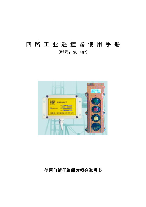
工业遥控器使用手册

工业遥控器使用手册第一项:质量保证与相关事项质量保证本产品出厂时,完全符合其所说明的各项规格,只要适当地安装,都可以正常地使用,但是我公司并不保证所有产品的操作是毫无中断或零错误。
保证时间本产品自出厂日起都可享有一年的保证期,保证客户在一年内不会有任何产品上的问题,若在保证期间内,只要证明产品品质有瑕疵,公司愿意维修,任何需要修护的产品,都必需送到本公司指定的服务处,该客户必须负担产品运往服务处的单程运费,而我公司的服务处在保证期间内会负担维护产品,寄还该产品,如果超过时间,来回运费都有客户负责。
未包含事项前述的保证范围,并未包含硅胶按键、继电器、保险丝、电池等损耗性零件或是装机错误所造成的基板损坏等,且未包含因客户不当使用、不可抗拒原因、天然因素、维护不足、操作环境规格的忽略、未经许可变更、错误使用或客户自行设置介面而造成的故障。
备注:前述的保证事项,并无其它明述或隐含的保证事项保证所提供的赔偿是客户唯一的赔偿,本公司并不负责任何直接、间接、特殊、意外或因果的损毁责任。
第二项:使用产品注意事项一般注意事项未经专业训练的人员,不得拆开本机器,否则可能损坏极造成人员受伤使用后行车总电源应关闭,以切断接收机电源,并将发射器的钥匙关闭拔掉行车应有总电源继电器、急停开关、极其它安全性设施。
按装注意事项1、接收器安装位置必须距离变频器、马达及其连接电源越远越好,以避免接收器受到杂讯的干拢2、接收器不可安装在电动葫芦控制箱内,正确安装方式是将接收器固定在电动葫芦控制箱顶部或者外部的适当位置,然后再将接收器电源穿入电动葫芦控制箱内做适当的接线3、本系列遥控器有40亿组的安全码,出厂时各安全码设定均不相同,惟安装时仍必须确认同一工作地区不能有相同安全码的遥控器,以避免相互影响而产品生错误操作4、prefix = st1 ns = "urn:schemas-microsoft-com:office:smarttags" 200米范围内不可以使用相同频道的设备,以避免无线电相互干拢5、请使用发射器时请带上发射器塑料PC外套,这样更加保护发射器的使用。
遥控器使用说明书

遥控器使用说明书一、面板说明1、“”键:机器通电并处于开启状态,按此键,机器进入关闭状态;机器通电并处于关闭状态,按此键,机器进入开启状态。
2、“Home”键:表示选择进入系统主页面;3、“Menu”键:在SW播放器界面,按此键弹出操作菜单;机器处于安卓系统界面,4、“”键:开启或关闭播放机声音。
5、“”键:按3秒钟,进入鼠标模式,可以通过遥控器方向键来控制鼠标的移动,再次按3秒钟退出鼠标模式。
6、“”键:方向键,可以向上移动光标;在鼠标模式可以向上移动鼠标7、“”键:方向键,可以向左移动光标;在鼠标模式可以向左移动鼠标8、“”键:方向键,可以向右移动光标;在鼠标模式可以向右移动鼠标9、“”键:方向键,可以向下移动光标;在鼠标模式可以向下移动鼠标10、“”键:此按键无功能11、“Vol+”键:调大播放机音量12、“OK”键:确定按钮13、“Vol-”键:调小音量14、“Tab”键:切换光标位置15、“”键:此按键无功能16、“”键:在SW播放器界面,按此键弹出操作菜单;安卓系统界面,返回上一级界面。
17、“1”键:输入数字1。
18、“2”键:输入数字219、“3”键:输入数字320、“4”键:输入数字421、“5”键:输入数字522、“6”键:输入数字623、“7”键:输入数字724、“8”键:输入数字825、“9”键:输入数字926、“0”键:输入数字027、“.”键:输入符号“.”28、“Del”键:删除文件或字符29、“Vod”键:此按键无功能30、“Live”键:此按键无功能31、“Pause”键:此按键无功能32、“Play”键:此按键无功能方向键包含:“”键、“”键、“”键和“”键。
数字键包含:“1”“2”“3”“4”“5”“6”“7”“8”“9”“0”“.”二、常用操作1,如何退出SW播放器按“Menu”键,弹出选择菜单,按向下方向键“”到“退出”,按“OK”键退出SW播放器。
2,如何设置网络连接2.1设置有线网络连接将RJ45网线连接播放机的有线网络插孔和网络交换机网络接口,播放机会自动识别有线网络并获取相应的IP地址。
F21-E1B工业遥控器说明书

F21-E1B工业遥控器说明书F21-E1B工业遥控器说明F21-E1B工业遥控器是利用无线电传输对工业机械进行远距离操作控制或远程控制的一种装置,工业遥控器是由无线发射电路板制成的发射装置来控制工业机械的运作。
工业遥控器:F21-2S,F21-RX,F21-4SB,F21-4S,F21-E1B,F21-E1,F23-A++,F23-RX,F23-BB,F24-8S,F24-RX,F24-10D,F24-12S,F24-12D,F24-60,F24-E1B工业遥控器要求精确度,灵敏度,信号连贯性,抗干扰性,遥控距离,防水防尘,耐高低温,耐酸碱性等技术参数,都比民用遥控器高,工业遥控器能适应各种恶劣环境;这些是民用遥控器所不能代替工业遥控器的原因。
工作遥控器的适用范围:1.不允许使用有线装置的场所2.想提高工作效率的场所3.环境恶劣,生物不能靠近的场所工业无线遥控器主要用于工业建筑、采矿、集装箱码头、仓储、机械制造、化工、造纸、工程机械等重工业领域,使用遥控器实现远程操作的行业。
一、F21-E1B8个单速按键 1个开机按钮/警铃,1个急停,6个功能按键操作距离半径100米工作温度-35`C—+80`C防护等级IP65(防水防尘)性能描述1.全系列软硬件完全兼容,可节省库存支出.2.可由电脑设定多种按键功能,如加速、捺跳、普通、抑制、延时等,可完全满足各种操作需求。
3.带有电池电压警示装置,在电压不足时能自行切断电路。
4.发射器电源:DC3V。
5.接收机电源:AC220V/380V,AC36V/48V,DC12V。
6.接收机含输出电缆,安装简单快速.二、F23-A++发射器(手持)尺寸:16.4×7.5×4.6厘米重量:约315克接收机尺寸:29×23×7厘米重量:1900克*10只单速按键(3号、4号键无效)*控制点数达11个*带有电池电压警示装置,在电压不足时能自行切断电路。
工业遥控手册
部分应用客户 四川芙蓉集团 厦门奥凯自动化 宁波三河 浙江金华机车 海南海口三亚 乌鲁木齐机场 内蒙古人造板厂 内蒙古化工集团 北京卖卡伦 美国麦克 大连保税区 海南三亚 北京国际英国学校 河南 285 军工厂 陕西杨凌 北京亦庄经济技术开发区 沈阳韩贝 云南昆明污水处理厂 大庆油田 长庆油田 中原油田 胜利油田 浙赣线电气化改造工程 渝怀线电气化改造工程 武威线电气化改造工程 京九线武汉段电气化改造工程 焦济线电气化改造工程 湛江港务局散货码头 广州船舶学校实验室 郑州大学新校区 郑州客属文化中心 河南安阳金鑫机床厂 武汉理工大实调机舱工程 湖北恩施烟草复烤厂 邯郸钢厂 山西海鑫钢厂 承德钢厂 天津钢厂 上海神火铝薄 平顶山十二矿 华能石粉 建河石粉 中兴国际机场
2、把接收控制器绝缘固定在配电柜内,把随机带的吸盘天线与地面垂直吸到金属控制箱 外壳或更高处2米以上即可,把吸盘天线连接头与接收器天线座连接拧紧。
3、检查无误,合闸送电,打开按遥控器电源开关,即可遥控。 4、不用时关掉遥控器电源有利于延长电池使用寿命,开关标识(—)为低时电源开、(○) 为低时电源关。 5、遥控距离变近,遥控指示灯微亮时要换电池,换电池时关掉电源开关,拧开遥控器后 壳六只固定螺钉取开后盖,再拧开压23A12V电池座两只螺钉换23A12V电池,换电池时注意电 池正极(+)、负极(-),23A12V电池上标有正极(+)、负极(-)标记,电池装反会烧坏遥 控电路。检查无误打开电源开关遥控指示灯亮表示正常,将遥控器后盖装上拧紧螺钉即可。
双流国际机场 五粮液集团 成都发动机厂 新疆众裕电子 广州地铁 小龙潭煤炭 河南南阳纺纱厂 邯钢精品钢工程 500KV 桂林变电站 内蒙中核北方燃料 翼北水泥计控改造 秦岭水泥厂 重庆天助水泥 福建电网公司 鹤璧万和电厂 三门峡铝业工程 青州卷烟厂 福建宁德电厂 张家口电厂 八一钢厂 德州重工碳素 安康旬阳锑矿 张河弯电厂 云南瑞安水泥 营口天瑞水泥 202 核燃料 香江万基铝业 新疆众裕电子 电动机保护器 神木九江商贸 新疆塔西河煤矿 哈尔乌苏煤矿 湖北恩施水电站 天津钢管厂 渭南 220KV 变电站 江苏起重机厂 沃尔沃 酒泉钢铁公司 武钢 大连机床厂 九江仪表厂 烟台机电设备厂 睿昌化工厂 北京国晶电器制造有限公司
控制器说明书
北京市凯商新技术开发有限公司KSC-10 控制器硬件使用手册v1.0KSC-10 控制器介绍KSC-10 可编程控制单元是为移动工程机械或液压传动机械设计的,可以为客户提供完备的开环或闭环控制。
KSC-10 控制器硬件电路设计满足工程车辆在复杂的工作环境如:高低温度,高湿度,强腐蚀,强震动,强电磁辐射下连续工作的要求,在硬件和软件上实现了闭环和自检测功能。
KSC-10 具有多路输入输出功能,并可以根据用户需要进行组合配置,输入可以根据需要配置为:模拟量采集,开关量采集或频率频率。
输出可以配置为开关量输出或模拟量比例输出,而且所有的输出都具有高负载驱动能力可以直接控制驱动单元,不用外挂其他的驱动单元,其中模拟量输出为PWM 恒流输出,可直接驱动哈维,力士乐等比例阀。
KSC-10 控制器采用16 位40MHz 汽车级专用C167 CPU 保证稳定工作和高性能计算能力,支持各种复杂的数据计算和过程控制,并配备了大容量的存储芯片,用户可以实现各种复杂的过程控制或算法。
具有扩展和组网功能:对于部分客户的一些复杂应用可以通过CAN 总线将几个控制器级联来增加输入输出能力。
上位机编程软件采用符合IEC61131-3 国际标准中文的编程环境,所有的菜单和调试过程中的提示和帮助系统都是中文,方便用户使用。
可以利用全部五种PLC 语言进行编程,并根据不同场合提供了大量的函数和软件驱动,用户可以直接调用自定义函数,节省开发时间和开发费用。
并增加了软件件仿真功能,可以直接在编程环境下对程序进行仿真,设置断点,单步运行等调试方法技术参数表一技术参数表二KSC-10接线图北京市凯商新技术开发有限公司C D B E A诊断 端 口G F1)确 保接 地: 用 一个 低 电阻 连 接线 接 地2)外 接 电磁 阀 的 地线 和 控制 器 工作 地 线分 开 3)建 议对 开 关和 传 感器 使 用单 独 的保 险 丝 4)CAN 总线 :建 议 使用 120? 的终 端 电阻 5)5v/地 可 以 单独 为 外部 传 感器 供 电6)开 关量 输 入为 高/低 有效 可 以通 过 软件 设 置 7)需 要 外 接一 大 于3v 的 电压 使 能所 有 输出8) 开 关量 输 入为 高 /低 有 效 可以 通 过软 件 设置北京市凯商新技术开发有限公司。
Liftertech KLIK3U 2 类门机遥控器综合说明书
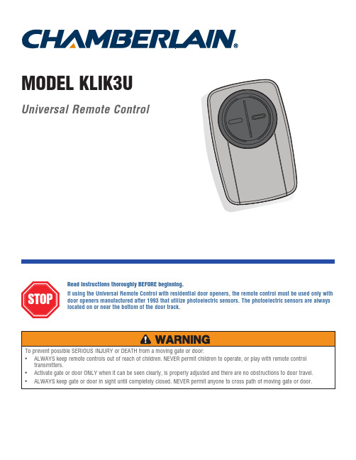
Universal Remote ControlRead instructions thoroughly BEFORE beginning.If using the Universal Remote Control with residential door openers, the remote control must be used only with door openers manufactured after 1993 that utilize photoelectric sensors. The photoelectric sensors are always located on or near the bottom of the door track.MODEL KLIK3UThe remote control can be programmed to activate up to two products, such as a garage door opener, gate operator, or commercial door operator. The images throughout this manual are for reference only and your product may look different.Button 2Programmed separately from Button 1.Garage Door OpenerCommercial Door OperatorGate OperatorButton 1Programmed separately from Button 2.Used for programming products with LEARN buttons.Depending on your product, there is a button (LEARN button) or DIP switches used for programming. You will need to locate the LEARN button or DIP switches on your product before you start programming. DIP SwitchesUsed for programming products with DIP switches.GARAGE DOOR OPENERSThe LEARN button or DIP switches are typically located on the back or side panel of your garage door opener. Your LEARN button may have a different name (SMART button, PROGRAM button, SET button, etc.). For help locating your LEARN button or DIP switches refer to the Helpsection in this manual or contact your garage door opener MERCIAL DOOR OPERATORSThe LEARN button or DIP switches are typically located on the logic board of your operator. Your LEARN button may have a different name (RADIO button, XMITTER button, etc.). For help locating your LEARN button or DIP switches contact your door operator manufacturer.GATE OPERATORSThe LEARN button or DIP switches are typically located on the control board of your operator. Your LEARN button may have a different name (RADIO button, XMITTER button, etc.). For help locating your LEARN button or DIP switches contact your gate operator manufacturer.Programming to a Garage Door Opener with a LEARN ButtonThe LEARN button is typically located on the back or side panel of the garage door opener or an external receiver. For help locating your LEARN button refer to the Help section in this manual or contact your garage door opener manufacturer. If you have a Genie ® Intellicode ® 2 garage door opener go to the next page.The images throughout this manual are for reference only and your product may look different.Program Button1Press the program button on the remote control until the LED turns on.2Press and release the LEARN button* on your garage door opener.3Press and release the remote control button, the LED will flash. When the LED stops flashing, continue to press and release the button (maximum of 9 times) until your garage door opener responds by clicking, blinking, or activating.4Press the program button on the remote control to save.5Test the remote control by pressing the button. If the garage door opener does not activate, repeat the programming steps orfollow the alternative programming option.* D epending on your product, the LEARN button may have a different name (usethe button for programming remote controls).LEDProgramming to a Genie ® Intellicode ® 2 Garage Door OpenerBefore starting, you MUST have a Genie ® Intellicode ® 2 remote control with at least one button already programmed to the garage door opener.The images throughout this manual are for reference only and your product may look different.1Press the program button on the Universal RemoteControl until the LED turns on.2Select a button to program and press that button 5 times, ensuring the LED stops flashing after each press .3Press the program button on the Universal Remote 4On the garage door opener, press and hold theProgram/Set button until both the long and short LED On the Universal Remote Control, press and release the same button again. Both LED’s on the garage door opener will light up BLUE.9On the Universal Remote Control, press and release the same button again. This will activate the garage door opener and programming is complete.If the door does not activate, repeat the steps.10Program ButtonLEDProgramming to a Commercial Door Operator with a LEARN ButtonThe LEARN button is typically located on the logic board of the operator or an external receiver. For help locating your LEARN button contact your commercial door operator manufacturer.The images throughout this manual are for reference only and your product may look different.1Press the program button on the remote control until the LED turns on.2Press and release the LEARN button* on your commercial door operator.3Press and release the remote control button, the LED will flash. When the LED stops flashing, continue to press and release the button until your commercial door operator responds by clicking, blinking, or activating.4Press the program button on the remote control to save.5Test the remote control by pressing the button. If the commercial door operator does not activate, repeat the programmingsteps or follow the alternative programming option.LEARN Button** D epending on your product, the LEARN button may have a different name (use the button for programming remote controls).Program ButtonLEDProgramming to a Gate Operator with a LEARN ButtonThe LEARN button is typically located on the control board of the operator or an external receiver. For help locating your LEARN button contact your gate operator manufacturer.The images throughout this manual are for reference only and your product may look different.1Press the program button on the remote control until the LED turns on.2Press and release the LEARN button* on your gate operator.3Press and release the remote control button, the LED will flash. When the LED stops flashing, continue to press and release the button until your gate operator responds by clicking, blinking, or activating.4Press the program button on the remote control to save.5Test the remote control by pressing the button. If the gate operator does not activate, repeat the programming steps or followthe alternative programming option.Learn Button** D epending on your product, the LEARN button may have a different name (usethe button for programming remote controls).Program ButtonProgram ButtonLEDProgramming to a GTO/Mighty Mule Gate Operator without a Remote ControlIf you have an existing GTO remote control go to the next page.The images throughout this manual are for reference only and your product may look different.Set the remote control DIP switches 1-9 to any combination.1Press the program button on the remote control until the LED turns on.23Press and release the remote control button, the LED will flash. When the LED stops flashing, continue to press and release the button 20 times, ensuring the LED stops flashing after each press . The code is accepted when the gate operator is activated.4Press the program button on the remote control to save.5Program the remote control to the gate operator (refer to the gate operator instructions).6Test the remote control by pressing the button. If the gateoperator does not activate, repeat the programming steps.Program ButtonProgram ButtonLEDProgramming to a GTO/Mighty Mule Gate Operator with a Remote Control=INITIAL SETUPIf you don’t have an existing GTO remote control go to the previous page.Before beginning, check the DIP switches on the GTO remote control. If any of the DIP switches are in the "0" position, move them to either the "+" or "-" position and reprogram the GTO remote control to the gate operator (refer to the gate operator instructions).The images throughout this manual are for reference only and your product may look different.2-BUTTON GTO REMOTE CONTROLIf the right button on the GTO remote control is programmed to the gate operator, the GTO remote control will need to be reprogrammed using the left button.3-BUTTON GTO REMOTE CONTROLIf the middle button on the GTO remote control is programmed to the gate operator, the GTO remote control will need to be reprogrammed using either the left or right button.NO DIP switches in the "0" position1Match the Universal Remote Control DIP switches to the GTO remote control DIP switches:GTO “+” = Universal Remote Control “ON”GTO “-” = Universal Remote Control “OFF”22-BUTTON GTO REMOTE CONTROLS ONLY: Set the 9th DIP switch on the Universal Remote Control to the “ON” position.3-BUTTON GTO REMOTE CONTROLS ONLY: Set the 9th DIP switch on the Universal Remote Control to the “ON” position if using the GTO left button or the “OFF” position if using the GTO right button.3Press the program button on the Universal Remote Control until the LED turns on.4Press and release the Universal Remote Control button, the LED will flash. When the LED stops flashing, continue to press and release the button 20 times, ensuring the LED stops flashing after each press . The code is accepted when the gate operator is activated.5Press the program button on the Universal Remote Control to save.6Test the Universal Remote Control by pressing the button. If the gate operator does not activate, repeat theprogramming steps.Program ButtonLED=Programming to an External Receiver with DIP Switches3 Position DIP Switch:For Chamberlain remotes DO NOT use the “0” position, use “+” or “-”.If you already have a 3-button remote, DIP switch #1 must be set to “-” if the large button is to open the door. It may be necessary to reprogram original remote controls.1Press the program button on the Universal Remote Control until the LED turns on.2Match the DIP switches between the existing remote control or external receiver and the Universal Remote Control. Turn extra switches OFF.32 Position DIP Switch:If programming fails reverse DIP switches (OFF to ON and ON to OFF).=External ReceiverDIP SwitchesDIP SwitchesExisting RemoteUniversal Remote ControlUniversal Remote ControlIf using the Universal Remote Control with residential door openers, the remote control must be used only with door openers manufactured after 1993 that utilize photoelectric sensors. The photoelectric sensors are always located on or near the bottom of the door track.The external receiver is typically located on the product or mounted near the product.The images throughout this manual are for reference only and your product may look different.Press and release the Universal Remote Control button, the LED will flash. When the LED stops flashing, continue to press and release the button until your product responds by clicking, blinking, or activating.4Press the program button on the Universal Remote Control to save.5Test the Universal Remote Control by pressing the button. If the product does not activate, repeat the programming steps or follow the alternative programming option.TIPSProgram ButtonProgram ButtonLEDProgramming to an External Receiver with a LEARN Button1Press the program button on the remote control until the LED turns on.2Press and release the LEARN button* on the external receiver.3Press and release the remote control button, the LED will flash. When the LED stops flashing, continue to press and release the button until your product responds by clicking, blinking, or activating.4Press the program button on the remote control to save.5Test the remote control by pressing the button. If the product does not activate, repeat the programming steps or follow thealternative programming option.Learn Button*If using the Universal Remote Control with residential door openers, the remote control must be used only with door openers manufactured after 1993 that utilize photoelectric sensors. The photoelectric sensors are always located on or near the bottom of the door track.The external receiver is typically located on the product or mounted near the product.The images throughout this manual are for reference only and your product may look different.* D epending on your product, the SMART/LEARN button may have a different name (use the button for programming remote controls).Program ButtonLEDAlternative programming option for products with a LEARN ButtonThe LEARN button is typically located on the product or an external receiver. For help locating your LEARN button refer to the Help section in this manual or contact your product manufacturer.The images throughout this manual are for reference only and your product may look different.** LiftMaster, Do-It, Master Mechanic, Raynor, True Value and Sears Craftsman are compatible with Chamberlain technology.1Press the program button on the remote control untilthe LED turns on.2P ress and release the LEARN button* on your product.The LED on the remote control must stop blinking between each press of the button. The code is accepted when the product responds by clicking, blinking, or activating.4Press the program button on the remote control tosave.5Test the remote control by pressing the button. If theproduct does not activate, repeat the programming steps.* D epending on your product, the LEARN button may have a different name (usethe button for programming remote controls).Program ButtonLEDAlternative programming option for products with DIP Switches...19 times (Chamberlain®** product with 7 DIP switches).The LED on the Universal Remote Control must stop blinking between each press of the button. The code is accepted when the garage door opener responds by clicking, blinking, or activating.=3 Position DIP Switch:use “+” or “-”. If you already have a 3-button remote, DIPswitch #1 must be set to “-” if the large button is to open thedoor. It may be necessary to reprogram original remote controls.1Press the program button on the Universal RemoteControl until the LED turns on.2Match the DIP switches between the existing remotecontrol or external receiver and the Universal RemoteControl. Turn extra switches OFF.5Press the program button on the Universal RemoteControl to save.6Test the Universal Remote Control by pressing the button.If the product does not activate, repeat the programmingsteps.2 Position DIP Switch:If programming fails reverse DIP switches (OFF to ONand ON to OFF).=ExternalReceiverDIP SwitchesDIP SwitchesExisting RemoteUniversalRemoteControlIf using the Universal Remote Control with residential door openers, the remote control must be used only with dooropeners manufactured after 1993 that utilize photoelectric sensors. The photoelectric sensors are always located on or near the bottom of the door track.The DIP switches are typically located on the product or an external receiver. For help locating your DIP switchescontact your product manufacturer.The images throughout this manual are for reference only and your product may look different.** LiftMaster, Do-It, Master Mechanic, Raynor, True Value and Sears Craftsman are compatible with Chamberlain technology.TIPSUniversalRemoteControlProgram ButtonLEDThe remote control will not program to a product with DIP switches.• Check the battery in the remote control. The LED should light when you press a button. Replace the battery if necessary.• I f programming with 2 position DIP switches, reverse the DIP switches (OFF to ON and ON to OFF), then repeat the programming steps.• F or Chamberlain remote controls DO NOT use the “0” position, use “+” or “-”. If you already have a 3-button remote, DIP switch #1 must be set to “-” if the large button is to open the door. It may be necessary to reprogram original remote controls.• Repeat the programming steps but make sure the LED stops flashing between each press of the remote control button.• Try programming using the Alternative Programming Option for products with a LEARN button.The remote control will not program to a product with a LEARN button.• Check the battery in the remote control. The LED should light when you press a button. Replace the battery if necessary.• Repeat the programming steps but make sure the LED stops flashing between each press of the remote control button.• Try programming using the Alternative Programming Option for products with DIP switches.The remote control LED will not light or it is dim.• Replace the battery.The remote control LED does not activate the product until it is close to the product.• Replace the battery.Locate the LEARN buttonLocate the LEARN buttonLearn CodeButtonProgram Set ButtonLocate the LEARN buttonLearnButtonLearnButtonProgram SWButtonLocate the LEARN buttonYellow LearnButtonPurple LearnButtonOrange LearnButtonGreen LearnButtonLearn CodeButtonLocate the LEARN buttonLearn ButtonChamberlain and LiftMaster are Trademarks of Chamberlain Group. Genie is a Trademark of Overhead Door Corporation. Overhead Door is a Trademark of Overhead Door Corporation. Linear is a Trademark of Linear Corporation. Master Mechanic is a Trademark of TruServ. Sears is a Trademark of Sears & Roebuck. Stanley is a Trademark of The Stanley Works. Wayne Dalton is a trademark of Wayne Dalton Corporation. Do It is a trademark of Do It Best Corporation. Mighty Mule and GTO are trademarks of Nortek Inc.Dispose of batteries properly. Replace ONLY with 3V2032 coin batteries.© 2014, The Chamberlain Group, Inc.All Rights Reserved114A4748 Online1-800-442-1255Battery。
工业控制器SE-607操作手册
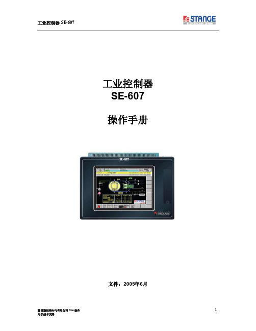
工业控制器SE-607 操作手册文件:2005年6月目录1 概要 41.1 关于本操作手册 41.2 符号说明 41.3 担保及责任 51.4 版权所有 52 安全事项62.1 使用目的 62.2 操作责任 62.3 操作人员 62.4 维护保养 62.5 维修72.6 生产商地址72.7 技术支持72.8 处理72.9 EU-标定73 运输, 包装和存放93.1 运输检查93.2 包装93.3 存放94 技术数据104.1 规格114.2 性能115 安装135.1 工业控制器SE-607安装须知135.2 安装说明概况135.3 控制柜上的安装135.4 面板剪切145.5 安装尺寸155.6 机械尺寸165.7 触摸屏说明175.7.1 触摸屏基本功能175.7.2 接电功能测试175.7.3 触摸屏清洁和维护176 调试186.1 接地和接线的原则186.2 接线概况196.3 插入C OMP ACTFLASH™206.4 插入电池216.5 电源接线226.6 屏蔽接线236.7 编程接口接线246.7.1 CAN接线256.7.2 键盘接线276.7.3 COM1 串口(RS232) 接线276.8 SE-607 与PC 相联286.8.1 布线286.9 以太网通讯时P C的设置286.9.1 要求286.9.2 设置Windows XP 296.9.3 在设备中设置IP-地址307 操作317.1 开机操作317.2 关机操作317.3 控制器的操作状态317.4 操作模式切换327.5 开机操作/ 启动337.6 诊断348 控制器操作界面358.1 操作358.1.1 设备示意图358.1.2 警报368.1.3 设定值378.1.4 开关量388.1.5 记录仪398.1.6 编辑操作程序398.1.7 控制418.1.8 登录438.1.9 更多功能438.2 程序编制448.2.1 输入程序448.2.2 装载操作448.2.3 删除448.2.4 程序输入448.2.5 程序输出448.2.6 程序分类448.2.7 程序复制458.2.8 编辑程序458.2.9 程序名称468.2.10 段时间478.2.11 设定值478.2.12 开关量488.2.13 段插入498.2.14 段删除508.3 设置508.3.1 日期/ 时钟508.3.2 语言528.3.3 IP-地址528.3.4 IO’s538.3.5 记录仪538.3.6 保存配置558.3.7 系统安装568.3.8 ECS 2000 信号568.3.9 PID 控制器578.3.10 极限值公差618.3.11 装载/ 删除数据648.3.12 实际值补偿表651 概况1.1关于本操作手册本操作手册旨在给予用户有关安装、操作、管理和服务正确的指导。
两路点动工业遥控开关使用手册
1、接收机安装应远离大面积金属物体、有剧烈震动、电机等电火花处,接收机安装方向和 天线安装方向应与地面垂直方向放置,且接收机和天线固定应离地面 2 米以上。
2、如遥控距离变近遥控指示灯发暗或遥控器电池严重欠压时,表示电池欠压请及时充电。
3、遥控器在不充电时要把充电器的交流电源插头和充电插头与座拔开,防止遥控器倒放电 消耗电池能量。
4、垂直拔出接线端子,红按扭为停止,对应接线端子标记是 1-B-C,把接线端子垂直 插入原插座,再将接线端子 B-C 控制线串联在 SB2 停止按扭常闭两端,按一下红按扭电机停 止;
5、将按接收控制器上盖紧固,再固定在离地面2米高的位置处,把随机带的吸盘天线与 地面垂直吸到金属控制箱上即可,把吸盘天线连接头与接收器天线连接座连接拧紧。
四、KW PC-2GY-R 接收器技术参数
1、 体 积:150 X 90 X 60mm 2、 重 量:600g 3、 使用温度:-40-80 度 4、 工作电压范围:交流220V(交流380V 220V 110V 直流6V 12V 24V 36V 48V选定) 5、 工作频率:315/433MHz 6、 触点电流:220V 7A 7、输出方式:无源两路常开常闭输出 8、常开输出:一组A-B 9、常闭输出:一组B-C
十一、型号说明Biblioteka 附件● 附件(标准配置):接收主机一个 吸盘天线一个 遥控器一个 智能全自动充电器一个 1800MA锂电充电电池一块(在遥控器内)使用说明一本
十二、售后服务
该产品返厂保修一年,长期负责维修,保修封签撕破、人伪损坏和天灾及不可抗拒原因损坏 不在保修之内。
北京首创电子实验室 北京康微英特电子科技有限公司
六、通过外接交流接触器控制电机启动停止接线示意图