开关电源top224芯片
TOP244Y单片开关电源原理及维修技巧

TOP244Y单片开关电源原理及维修技巧作者:刘宜新来源:《电子技术与软件工程》2016年第13期摘要本文首先概述了TOP244Y单片开关电源的基本工作原理,接着根据本人多年的维修实践经验,详细介绍了针对此电路的维修技巧,最后通过以TOP244Y单片开关电源维修实例进行剖析,进一步说明TOP244Y开关电源的具体维修技巧及故障的处理。
【关键词】开关电源 TOP244Y单片开关电源原理故障维修技巧开关电源又被称为高效节能电源,它不仅效率高,可达到80﹪-90﹪,而且去掉了笨重的工频变压器,它是利用体积很小的高频变压器来实现电压变换及电网隔离,这样为家用电器的小型化、轻型化奠定了坚实的基础。
采用TOP244Y单片开关电源用途非常广泛,很多民用家用电子产品都采用了此种电路方案,因此家电维修人员很有必要掌握TOP244Y单片开关电源的维修方法。
1 TOP244Y开关电源工作原理分析该开关电源芯片内含脉宽调制器、功率场效应管、自动偏置电路、保护电路。
再配合外部的一次整流滤波电路、、取样比较反馈电路、二次整流滤波电路等部分就组成了一个完整的单片开关电源。
其电路原理如附图所示,以下分别进行分析:1.1 TOP244Y芯片各引脚功能TOP244Y是一款集成式开关电源芯片,它将脉冲宽度调制(PWM)控制系统的全部功能集成到芯片中,其功能引脚如图1所示,各脚功能如下:1.1.1 漏极(D)引脚高压功率MOSFET的漏极输出,通过内部开关高压电流源提供启动偏置电流。
1.1.2 控制(C)引脚误差放大器及反馈电流的输入脚,用于占空比控制。
当控制引脚电压VC接近5.8 V时,控制电路被激活并开始软启动。
当出现开环或短路等故障而使外部电流无法流入控制引脚时,控制引脚上的电容开始放电,达到4.8 V时激活自动重启动电路而关断MOSFET开关管的输出,使控制电路进入低电流的待机模式。
同时该脚也是脉宽调制器电流反馈的控制脚,其占空比与流入控制脚超过芯片内部消耗所需要的电流成反比,实现脉宽调制。
单端正激式开关电源-主电路地设计

摘要:电源是各种电子设备不可或缺的组成部分,其性能优劣直接关系到电子设备的技术指标及能否安全可靠工作。
目前,开关电源因具有体积小、重量轻、效率高、发热量低、性能稳定等优点而逐渐取代传统技术制造的相控稳压电源,并广泛应用于电子设备中。
本设计的单端正激式开关电源是一种间接直流变流技术,本设计以正激电路为主体,采用以TOPSwitch系列开关电源集成芯片TOP244Y为核心的脉宽调制电路实现交-直-交-直变流,输出稳压稳频的直流电。
关键词开关电源;正激电路;变压器;脉宽调制;ABSTRACT Power is an indispensable part of electronic equipment, its performance directly related to electronic equipment technical indicators and safe work can. At present, switching power supply for has the advantages of small size, light weight, high efficiency, low calorific value and stable performance advantages and replace traditional technology of phased manostat, and widely used in electronic equipment.The design of the single straight separate-excited switching power supply is a kind of indirect dc converter technology, this design was adopted for the main circuit, induced by TOPSwitch series of switch power integration chip TOP244Y as the core of the pulse width modulation circuit implementation delivered straight into - - - the voltage output variable flow straight, dc frequency stability.KEY WORDS Switching power supply;Is induced circuit;Transformer;Pulse width modulation目录前言 (1)1. 开关电源的发展及趋势 (2)1.1 开关电源的发展历史 (3)1.2 开关电源的发展趋势 (3)2. 开关电源概念及基本原理 (4)2.1 开关电源概念 (5)2.1.1 基本概念 (5)2.1.2 开关电源通常由六大部分组成 (5)2.2 开关电源各部分电路基本原理 (5)2.2.1 脉宽调制式开关电源的基本原理 (5)2.2.2 TOPSwitch—GX系列TOP244Y芯片 (6)2.2.3 单相二极管整流桥 (7)2.2.4 缓冲电路(吸收电路) (8)2.2.5 正激电路 (9)2.2.6 开关电源中的滤波电路 (11)3. 开关电源变压器的设计 (13)3.1 确定磁心的尺寸 (13)3.2正激式变压器的设计 (15)3.2.1 变压器匝数比的确定 (16)3.3 变压器的绕线技术 (17)3.3.1 绕组符合安全规程 (17)3.3.2 低漏感的绕制方法 (18)3.3.3 变压器紧密耦合的绕制方法 (19)4. 单端正激式开关电源主电路设计 (22)4.1 输入电路设计 (22)4.2 正激电路的设计 (22)4.2.1 复位电路 (22)4.2.2 导向电路和续流电路 (23)4.2.3 抑制阻尼振荡电路 (23)4.3 正激变压器设计 (23)4.4 输出电路的设计 (23)5. 实验结果 (24)5.1 空载试验 (24)5.2 带金属负载试验 (25)4)TOPSwitch漏源极之间电压Uds 波形为 (25)5.3 试验过程出现的问题及解决 (25)结论 (26)致谢 (27)参考文献 (27)前言本课题主要是研究基于TOPSwitch—GX系列芯片TOP244Y构成的,以脉宽调制PWM为控制方式的高频单端正激式开关电源。
开关电源top224芯片

绪论开关电源(Switched Mode Power Supply,SMPS)是一种由占空比控制的开关电路构成的电能变换装置,用于交流—直流或直流—直流电能的变换.其功率从零点几瓦到数十千瓦,被广泛用于生活、生产、科研、军事等各个领域。
比如:小到彩色电视机、DVD播放机等家用电器、大到飞机、卫星、导弹、舰船中,都大量采用了开关电源。
开关电源的核心为电力电子开关电路,根据负载对电源提出的输出稳压或稳流特性的要求,利用反馈控制电路,采用占空比控制方法,对开关电路进行控制.脉宽调制(PWM)技术的发展,导致了PWM开关电源问世(PWM开关电源的特点是用20KHz的载波进行脉冲宽度调制,电源的效率可达65%~70%),大幅度节约了能源,引起了人们的广泛关注,在电源技术发展史上被誉为20KHz革命。
高频化使开关电源装置空前的小型化,并使其进入更广泛的领域,特别是推动了高新技术产品的小型化、轻便化,在节约资源及保护环境方面具有深远的意义.随着电子技术的高速发展,电子设备的应用领域越来越广,与人们的工作、生活的关系日益密切。
但是,任何电子设备都离不开可靠的电源,它们对电源的要求也越来越高.并且,随着集成芯片尺寸的不断减小,处理速度越来越高,需要更加小型化、轻量化的电源(磁性元件和电容的体积、重量应随之减小);未来的绿色电源要求开关电源的效率更高,性能更好,可靠性更高等.这一切将促进开关电源的不断发展和进步。
开关电源体积小、效率高,被誉为高效节能电源,现已成为稳压电源的主导产品。
当今开关电源正向着集成化、智能化的方向发展.高度集成、功能强大的开关型稳压电源代表着开关电源发展的主流方向。
本论文主要围绕当前流行的集成开关电源芯片进行小功率开关型稳压电源特性的研究。
本文采用TOP224Y研制了一款单片开关电源,论文给出了外围电路各部分的详细设计方法,并进行了参数计算,通过实测结果分析,验证了理论的可行性。
具有较强的适用性。
开关电源top224芯片

绪论开关电源(Switched Mode Power Supply,SMPS)是一种由占空比控制的开关电路构成的电能变换装置,用于交流—直流或直流—直流电能的变换。
其功率从零点几瓦到数十千瓦,被广泛用于生活、生产、科研、军事等各个领域。
比如:小到彩色电视机、DVD播放机等家用电器、大到飞机、卫星、导弹、舰船中,都大量采用了开关电源。
开关电源的核心为电力电子开关电路,根据负载对电源提出的输出稳压或稳流特性的要求,利用反馈控制电路,采用占空比控制方法,对开关电路进行控制。
脉宽调制(PWM)技术的发展,导致了PWM开关电源问世(PWM开关电源的特点是用20KHz的载波进行脉冲宽度调制,电源的效率可达65%~70%),大幅度节约了能源,引起了人们的广泛关注,在电源技术发展史上被誉为20KHz革命。
高频化使开关电源装置空前的小型化,并使其进入更广泛的领域,特别是推动了高新技术产品的小型化、轻便化,在节约资源及保护环境方面具有深远的意义。
随着电子技术的高速发展,电子设备的应用领域越来越广,与人们的工作、生活的关系日益密切。
但是,任何电子设备都离不开可靠的电源,它们对电源的要求也越来越高。
并且,随着集成芯片尺寸的不断减小,处理速度越来越高,需要更加小型化、轻量化的电源(磁性元件和电容的体积、重量应随之减小);未来的绿色电源要求开关电源的效率更高,性能更好,可靠性更高等。
这一切将促进开关电源的不断发展和进步。
开关电源体积小、效率高,被誉为高效节能电源,现已成为稳压电源的主导产品。
当今开关电源正向着集成化、智能化的方向发展。
高度集成、功能强大的开关型稳压电源代表着开关电源发展的主流方向。
本论文主要围绕当前流行的集成开关电源芯片进行小功率开关型稳压电源特性的研究。
本文采用TOP224Y研制了一款单片开关电源,论文给出了外围电路各部分的详细设计方法,并进行了参数计算,通过实测结果分析,验证了理论的可行性。
具有较强的适用性。
逆变器辅助电源
最简单的逆变器辅助电源
主题: 一款用于逆变器辅助电源的电路
一款逆变器如果要其性能稳定可靠,其辅助电源的设计是很要紧的,既要成本低廉,又要性能不错,有很多厂家在生产逆变器时,用于TOP104的比较多,但现在有一个问题,因为TOP104在国外已经停产,现在能买到的大多数是拆机的或者旧贷,性能得不到保证,我这几天试了一下,用TOP223P(G)或TOP224P(G)做辅助电源,发现很好用,和TOP104相比有几个好处:
1、TOP223-224都还在生产,可以买到新货,生产不用愁;
2、TOP223-224是DIP8脚封装的,比TOP107的220封装,安装要方便很多,高度降低不少;
3、在低压下使用,TOP104有些芯片工作不稳定,要停振,而223-224就没有这个问题,很容易起振
且工作稳定。
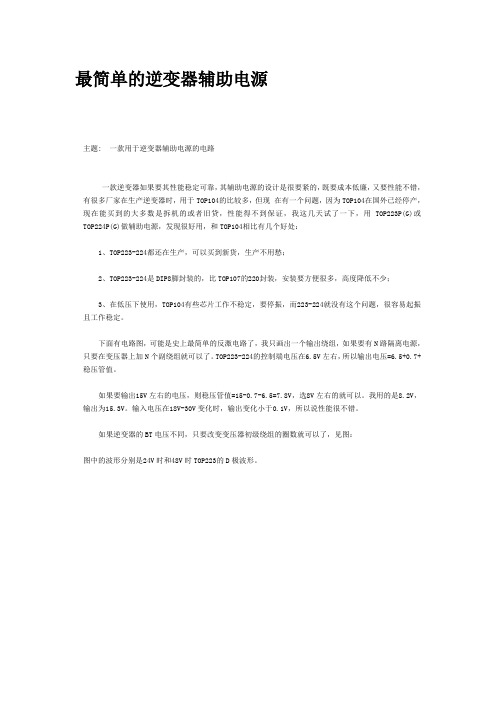
下面有电路图,可能是史上最简单的反激电路了,我只画出一个输出绕组,如果要有N路隔离电源,只要在变压器上加N个副绕组就可以了。
TOP223-224的控制端电压在6.5V左右,所以输出电压=6.5+0.7+稳压管值。
如果要输出15V左右的电压,则稳压管值=15-0.7-6.5=7.8V,选8V左右的就可以。
我用的是8.2V,输出为15.3V。
输入电压在18V-30V变化时,输出变化小于0.1V,所以说性能很不错。
如果逆变器的BT电压不同,只要改变变压器初级绕组的圈数就可以了,见图:
图中的波形分别是24V时和48V时TOP223的D极波形。
TOP224

Figure 1. Typical Flyback Application.easier. The standard 8L PDIP package option reduces cost in lower power, high efficiency applications. The internal lead frame of this package uses six of its pins to transfer heat from the chip directly to the board, eliminating the cost of a heat sink.TOPSwitch incorporates all functions necessary for a switched mode control system into a three terminal monolithic IC: power MOSFET, PWM controller, high voltage start up circuit, loop compensation and fault protection circuitry.Product Highlights•Lowest cost, lowest component count switcher solution •Cost competitive with linears above 5W•Very low AC/DC losses – up to 90% efficiency •Built-in Auto-restart and Current limiting•Latching Thermal shutdown for system level protection •Implements Flyback, Forward, Boost or Buck topology •Works with primary or opto feedback•Stable in discontinuous or continuous conduction mode •Source connected tab for low EMI•Circuit simplicity and Design Tools reduce time to marketDescriptionThe second generation TOPSwitch-II family is more cost effective and provides several enhancements over the first generation TOPSwitch family. The TOPSwitch-II family extends the power range from 100W to 150W for 100/115/230 VAC input and from 50W to 90W for 85-265 VAC universal input.This brings TOPSwitch technology advantages to many new applications, i.e. TV, Monitor, Audio amplifiers, etc. Many significant circuit enhancements that reduce the sensitivity to board layout and line transients now make the design evenNotes: 1. Package outline: TO-220/3 2. Package Outline: DIP-8 or SMD-8 3. 100/115 VAC with doubler input 4. Assumes appropriateheat sinking to keep the maximum TOPSwitch junction temperature below 100 °C. 5. Soldered to 1 sq. in.( 6.45 cm 2), 2 oz. copper clad (610 gm/m 2) 6. P MAX is the maximum practical continuous power output level for conditions shown. The continuous power capability in a given application depends on thermal environment, transformer design, efficiency required, minimum specified input voltage, input storage capacitance, etc. 7. Refer to key application considerations section when using TOPSwitch-II in an existing TOPSwitch design.July 2001Figure 2. Functional Block Diagram.Pin Functional DescriptionDRAIN Pin:Output MOSFET drain connection. Provides internal biascurrent during start-up operation via an internal switched high-voltage current source. Internal current sense point.CONTROL Pin:Error amplifier and feedback current input pin for duty cyclecontrol. Internal shunt regulator connection to provide internalbias current during normal operation. It is also used as theconnection point for the supply bypass and auto-restart/compensation capacitor.SOURCE Pin:Y package – Output MOSFET source connection for highvoltage power return. Primary side circuitcommon and reference point.P and G package – Primary side control circuit common andreference point.SOURCE (HV RTN) Pin: (P and G package only)Output MOSFET source connection for high voltage power return.Figure 3. Pin Configuration.D 7/01TOPSwitch-II Family Functional DescriptionTOPSwitch is a self biased and protected linear control current-to-duty cycle converter with an open drain output. High efficiency is achieved through the use of CMOS and integration of the maximum number of functions possible. CMOS process significantly reduces bias currents as compared to bipolar or discrete solutions. Integration eliminates external power resistors used for current sensing and/or supplying initial start-up bias current.During normal operation, the duty cycle of the internal output MOSFET decreases linearly with increasing CONTROL pin current as shown in Figure 4. To implement all the required control, bias, and protection functions, the DRAIN and CONTROL pins each perform several functions as described below. Refer to Figure 2 for a block diagram and to Figure 6 for timing and voltage waveforms of the TOPSwitch integrated circuit.Figure 4. Relationship of Duty Cycle to CONTROL Pin Current.Figure 5. Start-up Waveforms for (a) Normal Operation and (b) Auto-restart.Control Voltage SupplyCONTROL pin voltage VCis the supply or bias voltage for thecontroller and driver circuitry. An external bypass capacitorclosely connected between the CONTROL and SOURCE pinsis required to supply the gate drive current. The total amountof capacitance connected to this pin (CT) also sets the auto-restart timing as well as control loop compensation. VCisregulated in either of two modes of operation. Hystereticregulation is used for initial start-up and overload operation.Shunt regulation is used to separate the duty cycle error signalfrom the control circuit supply current. During start-up,CONTROL pin current is supplied from a high-voltage switchedcurrent source connected internally between the DRAIN andCONTROL pins. The current source provides sufficient currentto supply the control circuitry as well as charge the totalexternal capacitance (CT).The first time VCreaches the upper threshold, the high-voltagecurrent source is turned off and the PWM modulator and outputtransistor are activated, as shown in Figure 5(a). During normaloperation (when the output voltage is regulated) feedbackcontrol current supplies the VCsupply current. The shuntregulator keeps VCat typically 5.7 V by shunting CONTROLpin feedback current exceeding the required DC supply currentthrough the PWM error signal sense resistor RE. The lowdynamic impedance of this pin (ZC) sets the gain of the erroramplifier when used in a primary feedback configuration. Thedynamic impedance of the CONTROL pin together with theexternal resistance and capacitance determines the control loopcompensation of the power system.If the CONTROL pin total external capacitance (CT) shoulddischarge to the lower threshold, the output MOSFET is turnedoff and the control circuit is placed in a low-current standbymode. The high-voltage current source turns on and charges theexternal capacitance again. Charging current is shown with anegative polarity and discharging current is shown with apositive polarity in Figure 6. The hysteretic auto-restartcomparator keeps VCwithin a window of typically 4.7 to 5.7 Vby turning the high-voltage current source on and off as shownin Figure 5(b). The auto-restart circuit has a divide-by-8counter which prevents the output MOSFET from turning onagain until eight discharge-charge cycles have elapsed. Thecounter effectively limits TOPSwitch power dissipation byreducing the auto-restart duty cycle to typically 5%. Auto-restart continues to cycle until output voltage regulation isagain achieved.Bandgap ReferenceAll critical TOPSwitch internal voltages are derived from atemperature-compensated bandgap reference. This referenceis also used to generate a temperature-compensated currentsource which is trimmed to accurately set the oscillator frequencyOscillatorThe internal oscillator linearly charges and discharges theinternal capacitance between two voltage levels to create asawtooth waveform for the pulse width modulator. The oscillatorsets the pulse width modulator/current limit latch at the beginningof each cycle. The nominal frequency of 100 kHz was chosento minimize EMI and maximize efficiency in power supplyapplications. Trimming of the current reference improves thefrequency accuracy.Pulse Width ModulatorThe pulse width modulator implements a voltage-mode controlloop by driving the output MOSFET with a duty cycle inverselyproportional to the current into the CONTROL pin whichgenerates a voltage error signal across RE. The error signalacross REis filtered by an RC network with a typical cornerfrequency of 7 kHz to reduce the effect of switching noise. Thefiltered error signal is compared with the internal oscillatorsawtooth waveform to generate the duty cycle waveform. Asthe control current increases, the duty cycle decreases. A clocksignal from the oscillator sets a latch which turns on the outputMOSFET. The pulse width modulator resets the latch, turningoff the output MOSFET. The maximum duty cycle is set by thesymmetry of the internal oscillator. The modulator has aminimum ON-time to keep the current consumption of theTOPSwitch independent of the error signal. Note that a minimumcurrent must be driven into the CONTROL pin before the dutycycle begins to change.Gate DriverThe gate driver is designed to turn the output MOSFET on at acontrolled rate to minimize common-mode EMI. The gate drivecurrent is trimmed for improved accuracy.Error AmplifierThe shunt regulator can also perform the function of an erroramplifier in primary feedback applications. The shunt regulatorvoltage is accurately derived from the temperature compensatedbandgap reference. The gain of the error amplifier is set by theCONTROL pin dynamic impedance. The CONTROL pinclamps external circuit signals to the VCvoltage level. TheCONTROL pin current in excess of the supply current isseparated by the shunt regulator and flows through REas avoltage error signal.Cycle-By-Cycle Current LimitThe cycle by cycle peak drain current limit circuit uses theoutput MOSFET ON-resistance as a sense resistor. A currentlimit comparator compares the output MOSFET ON-state drain-source voltage, VDS(ON)with a threshold voltage. High draincurrent causes VDS(ON)to exceed the threshold voltage and turnsthe output MOSFET off until the start of the next clock cycle.The current limit comparator threshold voltage is temperature TOPSwitch-II Family Functional Description (cont.)D 7/01compensated to minimize variation of the effective peak current limit due to temperature related changes in output MOSFET R DS(ON).The leading edge blanking circuit inhibits the current limit comparator for a short time after the output MOSFET is turned on. The leading edge blanking time has been set so that current spikes caused by primary-side capacitances and secondary-side rectifier reverse recovery time will not cause premature termination of the switching pulse.The current limit can be lower for a short period after the leading edge blanking time as shown in Figure 12. This is due to dynamic characteristics of the MOSFET. To avoid triggering the current limit in normal operation, the drain current waveform should stay within the envelope shown.Shutdown/Auto-restartTo minimize TOPSwitch power dissipation, the shutdown/auto-restart circuit turns the power supply on and off at an auto-restart duty cycle of typically 5% if an out of regulation condition persists. Loss of regulation interrupts the external current into the CONTROL pin. V C regulation changes from shunt mode to the hysteretic auto-restart mode described above.When the fault condition is removed, the power supply outputbecomes regulated, V C regulation returns to shunt mode, and normal operation of the power supply resumes.Overtemperature ProtectionTemperature protection is provided by a precision analog circuit that turns the output MOSFET off when the junction temperature exceeds the thermal shutdown temperature (typically 135 °C). Activating the power-up reset circuit by removing and restoring input power or momentarily pulling the CONTROL pin below the power-up reset threshold resets the latch and allows TOPSwitch to resume normal power supply operation. V C is regulated in hysteretic mode and a 4.7 V to 5.7 V (typical) sawtooth waveform is present on the CONTROL pin when the power supply is latched off.High-voltage Bias Current SourceThis current source biases TOPSwitch from the DRAIN pin and charges the CONTROL pin external capacitance (C T ) during start-up or hysteretic operation. Hysteretic operation occurs during auto-restart and overtemperature latched shutdown.The current source is switched on and off with an effective duty cycle of approximately 35%. This duty cycle is determined by the ratio of CONTROL pin charge (I C ) and discharge currents (I CD1 and I CD2). This current source is turned off during normal operation when the output MOSFET is switching.Figure 6. Typical Waveforms for (1) Normal Operation, (2) Auto-restart, and (3) Power Down Reset.Figure 7. Schematic Diagram of a 4 W TOPSwitch-II Standby Power Supply using an 8 lead PDIP.Application ExamplesFollowing are just two of the many possible TOPSwitchimplementations. Refer to the Data Book and Design Guidefor additional examples.4 W Standby Supply using 8 Lead PDIPFigure 7 shows a 4 W standby supply. This supply is used inappliances where certain standby functions (e.g. real timeclock, remote control port) must be kept active even while themain power supply is turned off.The 5 V secondary is used to supply the standby function andthe 12 V non-isolated output is used to supply power for thePWM controller of the main power supply and other primaryside functions.For this application the input rectifiers and input filter are sizedfor the main supply and are not shown. The input DC rail mayvary from 100 V to 380 V DC which corresponds to the fulluniversal AC input range. The TOP221 is packaged in an 8 pinpower DIP package.The output voltage (5 V) is directly sensed by the Zener diode(VR1) and the optocoupler (U2). The output voltage is determinedby the sum of the Zener voltage and the voltage drop across theLED of the optocoupler (the voltage drop across R1 is negligible).The output transistor of the optocoupler drives the CONTROLpin of the TOP221. C5 bypasses the CONTROL pin and providescontrol loop compensation and sets the auto-restart frequency.The transformer’s leakage inductance voltage spikes are snubbedby R3 and C1 through diode D1. The bias winding is rectifiedand filtered by D3 and C4 providing a non-isolated 12 V outputwhich is also used to bias the collector of the optocoupler’soutput transistor. The isolated 5 V output winding is rectified byD2 and filtered by C2, L1 and C3.D 7/0120 W Universal Supply using 8 Lead PDIPFigure 8 shows a 12 V, 20 W secondary regulated flyback power supply using the TOP224P in an eight lead PDIP package and operating from universal 85 to 265 VAC input voltage. This example demonstrates the advantage of the higher power 8 pin leadframe used with the TOPSwitch-II family. This low cost package transfers heat directly to the board through six source pins, eliminating the heatsink and the associated cost. Efficiency is typically 80% at low line input. Output voltage is directly sensed by optocoupler U2 and Zener diode VR2. The output voltage is determined by the Zener diode (VR2) voltage and the voltage drops across the optocoupler (U2) LED and resistor R1.Other output voltages are possible by adjusting the transformer turns ratio and value of Zener diode VR2.AC power is rectified and filtered by BR1 and C1 to create the high voltage DC bus applied to the primary winding of T1. The other side of the transformer primary is driven by the integrated TOPSwitch-II high-voltage MOSFET. D1 and VR1 clampleading-edge voltage spikes caused by transformer leakage inductance. The power secondary winding is rectified and filtered by D2, C2, L1, and C3 to create the 12 V output voltage.R2 and VR2 provide a slight pre-load on the 12 V output to improve load regulation at light loads. The bias winding is rectified and filtered by D3 and C4 to create a TOPSwitch bias voltage. L2 and Y1-safety capacitor C7 attenuate common mode emission currents caused by high voltage switching waveforms on the DRAIN side of the primary winding and the primary to secondary capacitance. Leakage inductance of L2with C1 and C6 attenuates differential-mode emission currents caused by the fundamental and harmonics of the trapezoidal or triangular primary current waveform. C5 filters internal MOSFET gate drive charge current spikes on the CONTROL pin, determines the auto-restart frequency, and together with R1 and R3, compensates the control loop.Figure 8. Schematic Diagram of a 20 W Universal Input TOPSwitch-II Power Supply using an 8 lead PDIP.Key Application ConsiderationsGeneral Guidelines• Keep the SOURCE pin length very short. Use a Kelvinconnection to the SOURCE pin for the CONTROL pinbypass capacitor. Use single point grounding techniques atthe SOURCE pin as shown in Figure 9.• Minimize peak voltage and ringing on the DRAIN voltageat turn-off. Use a Zener or TVS Zener diode to clamp thedrain voltage below the breakdown voltage rating ofTOPSwitch under all conditions, including start-up andoverload. The maximum recommended clamp Zenervoltage for the TOP2XX series is 200 V and thecorresponding maximum reflected output voltage on theprimary is 135 V. Please see Step 4: AN-16 in the 1996-97Data Book and Design Guide or on our Web site.• The transformer should be designed such that the rate ofchange of drain current due to transformer saturation iswithin the absolute maximum specification (∆IDin 100 nsbefore turn off as shown in Figure 13). As a guideline, formost common transformer cores, this can be achieved bymaintaining the Peak Flux Density (at maximum ILIMITcurrent) below 4200 Gauss (420 mT). The transformerspreadsheets Rev. 2.1 (or later) for continuous and Rev.1.0(or later) for discontinuous conduction mode provide thenecessary information.• Do not plug TOPSwitch into a “hot” IC socket during test.External CONTROL pin capacitance may be charged toexcessive voltage and cause TOPSwitch damage.• While performing TOPSwitch device tests, do not exceedmaximum CONTROL pin voltage of 9 V or maximumCONTROL pin current of 100 mA.• Under some conditions, externally provided bias or supplycurrent driven into the CONTROL pin can hold theTOPSwitch in one of the 8 auto-restart cycles indefinitelyand prevent starting. To avoid this problem when doingbench evaluations, it is recommended that the VCpowersupply be turned on before the DRAIN voltage is applied.TOPSwitch can also be reset by shorting the CONTROLpin to the SOURCE pin momentarily.• CONTROL pin currents during auto-restart operation aremuch lower at low input voltages (< 36 V) which increasesthe auto-restart cycle time (see the ICvs. DRAIN VoltageCharacteristic curve).• Short interruptions of AC power may cause TOPSwitch toenter the 8-count auto-restart cycle before starting again.This is because the input energy storage capacitors are notcompletely discharged and the CONTROL pin capacitancehas not discharged below the internal power-up resetvoltage.• In some cases, minimum loading may be necessary to keepa lightly loaded or unloaded output voltage within thedesired range due to the minimum ON-time.Replacing TOPSwitch with TOPSwitch-IIThere is no external latching shutdown function inTOPSwitch-II. Otherwise, the functionality of theTOPSwitch-II devices is same as that of the TOPSwitch family.However, before considering TOPSwitch-II as a 'drop in'replacement in an existing TOPSwitch design, the designshould be verified as described below.The new TOPSwitch-II family offers more power capabilitythan the original TOPSwitch family for the same MOSFETRDS(ON). Therefore, the original TOPSwitch design must bereviewed to make sure that the selected TOPSwitch-IIreplacement device and other primary components are not overstressed under abnormal conditions.The following verification steps are recommended:• Check the transformer design to make sure that it meets the∆IDspecification as outlined in the General Guidelinessection above.• Thermal: Higher power capability of the TOPSwitch-IIwould in many instances allow use of a smaller MOSFETdevice (higher RDS(ON)) for reduced cost. This may affectTOPSwitch power dissipation and power supply efficiency.Therefore thermal performance of the power supply mustbe verified with the selected TOPSwitch-II device.• Clamp Voltage: Reflected and Clamp voltages should beverified not to exceed recommended maximums for theTOP2XX Series: 135 V Reflected/200 V Clamp. Pleasesee Step 4: AN-16 in the Data Book and Design Guide andreadme.txt file attached to the transformer designspreadsheets.• Agency Approval: Migrating to TOPSwitch-II may requireagency re-approval.D 7/01Figure 9. Recommended TOPSwitch Layout.Design ToolsThe following tools available from Power Integrations greatly simplify TOPSwitch based power supply design.• Data Book and Design Guide includes extensive application information• Excel Spreadsheets for Transformer Design - Use of this tool is strongly recommended for all TOPSwitch designs.• Reference design boards – Production viable designs that are assembled and tested.All data sheets, application literature and up-to-date versions of the Transformer Design Spreadsheets can be downloaded from our Web site at . A diskette of the Transformer Design Spreadsheets may also be obtained by sending in the completed form provided at the end of this data sheet.D 7/01D 7/01NOTES:A.For specifications with negative values, a negative temperature coefficient corresponds to an increase in magnitude with increasing temperature, and a positive temperature coefficient corresponds to a decrease in magnitude with increasing temperature.B.The breakdown voltage and leakage current measurements can be accomplished as shown in Figure 15 by using the following sequence:i. The curve tracer should initially be set at 0 V. The base output should be adjusted through a voltage sequence of 0 V, 6.5 V, 4.3 V, and 6.5 V, as shown. The base current from the curve tracer should not exceed 100 mA. This CONTROL pin sequence interrupts the Auto-restart sequence and locks the TOPSwitch internal MOSFET in the OFF State.ii. The breakdown and the leakage measurements can now be taken with the curve tracer. The maximum voltage from the curve tracer must be limited to 700 V under all conditions.C.It is possible to start up and operate TOPSwitch at DRAIN voltages well below 36 V. However, the CONTROL pin charging current is reduced, which affects start-up time, auto-restart frequency, and auto-restart duty cycle. Refer to the characteristic graph on CONTROL pin charge current (I C ) vs. DRAIN voltage for low voltage operation characteristics.Figure 11. TOPSwitch CONTROL Pin I-V Characteristic. Figure 10. TOPSwitch Duty Cycle Measurement.Figure 12. Self-protection Current Limit Envelope.Figure 13. Example of ∆IDon Drain Current Waveform withSaturated Transformer.012683Time (µs)DRAINCurrent(normalized)PI-222-331457120100804020600246810CONTROL Pin Voltage (V)CONTROLPinCurrent(mA)D 7/01Figure 14. TOPSwitch General Test Circuit.Figure 15. Breakdown Voltage and Leakage Current Measurement Test Circuit.The following precautions should be followed when testingTOPSwitch by itself outside of a power supply. The schematicshown in Figure 14 is suggested for laboratory testing ofTOPSwitch.When the DRAIN supply is turned on, the part will be in theAuto-restart mode. The CONTROL pin voltage will beoscillating at a low frequency from 4.7 to 5.7 V and the DRAINis turned on every eighth cycle of the CONTROL pin oscillation.If the CONTROL pin power supply is turned on while in thisTypical Performance CharacteristicsAuto-restart mode, there is only a 12.5% chance that the controlpin oscillation will be in the correct state (DRAIN active state)so that the continuous DRAIN voltage waveform may beobserved. It is recommended that the VCpower supply beturned on first and the DRAIN power supply second if continuousdrain voltage waveforms are to be observed. The 12.5% chanceof being in the correct state is due to the 8:1 counter. Temporarilyshorting the CONTROL pin to the SOURCE pin will resetTOPSwitch, which then will come up in the correct state.21.21.6020*********DRAIN Voltage (V)CONTROLPinChargingCurrent(mA)I C vs. DRAIN VOLTAGEPI-1145-131940.40.81.11.00.9-50-250255075100125150Junction Temperature (°C)BreakdownVoltage(V)(Normalizedto25°C)BREAKDOWN vs. TEMPERATUREPI-176B-513911.21.00.80.60.40.2-50-250255075100125150Junction Temperature (°C)CURRENT LIMIT vs. TEMPERATUREPI-1125-331CurrentLimit(Normalizedto25°C)1.21.00.80.60.40.2-50-250255075100125150Junction Temperature (°C)FREQUENCY vs. TEMPERATUREPI-1123A-331OutputFrequency(Normalizedto25°C)D 7/01Typical Performance Characteristics (cont.)3246810DRAIN Voltage (V)D R A I N C u r r e n t (A )OUTPUT CHARACTERISTICSP I -1940-03300112100010400200600DRAIN Voltage (V)D R A I N C a p a c i t a n c e (p F )C OSS vs. DRAIN VOLTAGE100P I -1941-033001500300400100200200400600DRAIN Voltage (V)P o w e r (m W )DRAIN CAPACITANCE POWERP I -1942-0330017/01Notes-1) Updated package references.2) Corrected Spelling.3) Corrected Storage Temperature θJCand updated nomenclature in parameter table.4) Added G package references to Self-Protection Current Limit parameter.5) Corrected font sizes in figures.Date12/977/01 RevisionCDKOREAPower IntegrationsInternational Holdings, Inc.Rm# 402, Handuk Building649-4 Yeoksam-Dong,Kangnam-Gu,Seoul, KoreaPhone:+82-2-568-7520Fax:+82-2-568-7474e-mail: koreasales@WORLD HEADQUARTERSAMERICASPower Integrations, Inc.5245 Hellyer AvenueSan Jose, CA 95138 USAMain:+1 408-414-9200Customer Service:Phone:+1 408-414-9665Fax:+1 408-414-9765e-mail: usasales@For the latest updates, visit our Web site:Power Integrations reserves the right to make changes to its products at any time to improve reliability or manufacturability. Power Integrations does not assume any liability arising from the use of any device or circuit described herein, nor does it convey any license under its patent rights or the rights of others.The PI Logo, TOPSwitch, TinySwitch and EcoSmart are registered trademarks of Power Integrations, Inc.©Copyright 2001, Power Integrations, Inc.JAPANPower Integrations, K.K.Keihin-Tatemono 1st Bldg.12-20 Shin-Yokohama 2-ChomeKohoku-ku, Yokohama-shiKanagawa 222-0033, JapanPhone:+81-45-471-1021Fax:+81-45-471-3717e-mail: japansales@TAIWANPower IntegrationsInternational Holdings, Inc.17F-3, No. 510Chung Hsiao E. Rd.,Sec. 5,Taipei, Taiwan 110, R.O.C.Phone:+886-2-2727-1221Fax:+886-2-2727-1223e-mail: taiwansales@EUROPE & AFRICAPower Integrations (Europe) Ltd.Centennial CourtEasthampstead RoadBracknellBerkshire, RG12 1YQUnited KingdomPhone:+44-1344-462-300Fax:+44-1344-311-732e-mail: eurosales@CHINAPower IntegrationsInternational Holdings, Inc.Rm# 1705, Bao Hua Bldg.1016 Hua Qiang Bei LuShenzhen, Guangdong 518031ChinaPhone:+86-755-367-5143Fax:+86-755-377-9610e-mail: chinasales@INDIA (Technical Support)Innovatech#1, 8th Main RoadVasanthnagarBangalore, India 560052Phone:+91-80-226-6023Fax:+91-80-228-9727e-mail: indiasales@APPLICATIONS HOTLINEWorld Wide +1-408-414-9660APPLICATIONS FAXWorld Wide +1-408-414-9760。
一种基于TOP224Y的单片开关电源设计

一种基于TOP224Y的单片开关电源设计TOP224Y是Power Integrations公司生产的一种集成开关电源控制器芯片。
它具有高精度的可调输出电压和电流限制功能,适用于各种应用,包括家庭电器、工业电器、通信设备等。
在设计基于TOP224Y的单片开关电源时,需要考虑以下几个方面:1.输入电路设计:输入电路包括输入滤波电容、输入电感和输入电桥等。
输入滤波电容用于减小输入端的噪声,输入电感用于增加滤波效果,输入电桥用于变换输入交流电为直流电。
输入电感和输入电桥的参数需要根据具体应用进行选择。
2.输出电路设计:输出电路包括输出电感、输出滤波电容和输出二极管等。
输出电感用于平滑输出电流,输出滤波电容用于减小输出端的纹波电压,输出二极管用于提供反向电流通路。
输出电感和输出滤波电容的参数也需要根据具体应用进行选择。
3.控制电路设计:控制电路包括反馈电路和PWM控制电路。
反馈电路用于检测输出电压,并通过比较器将检测到的输出电压与参考电压进行对比,从而调整PWM控制电路的输出占空比以实现稳定的输出电压。
PWM控制电路则由TOP224Y芯片提供,通过调整输入电压和PWM控制电路的输出占空比来实现恒定的输出电压。
4.保护电路设计:保护电路用于防止电源过载、过温和短路等故障。
过载保护可通过在输出端增加一个过载保护电路,当输出电流超过预设的电流限制时,过载保护电路将切断电源输入。
过温保护可通过在芯片上增加一个温度传感器来实现,当芯片温度超过一定阈值时,温度传感器将切断电源输入。
短路保护可通过在输出端增加一个短路保护电路,当输出短路时,短路保护电路将切断电源输入。
5.PCB布局设计:PCB布局设计需要考虑信号和功率之间的隔离,以减小干扰和提高抗干扰能力。
将输入电路和输出电路分开布局,并合理规划各个元件的位置,以最小化信号干扰。
在实际应用中,还需要根据具体需求对开关电源进行额外的优化。
比如,可以添加输入过滤电路和输出稳压电路,以提高输入电路的稳定性和输出电路的稳定性。
基于TOP244的开关电源设计

(3) G型:采用表面帖封式SMD-8B封装。 Y型封装需外加散热器,P/G型封装可借助 印刷板上公共地区域来代替散热器,将S
极焊接在敷铜板上。
❖ 漏极管脚(D):高压功率MOSFET漏极输出。
❖ 控制管脚(C):用于调节占空比的误差放大器
❖ 源极 管 脚 (S):将其连接至输出MOSFET源极可得 到高压功率回馈。
❖ 芯片内部工作原理:
❖ 电源启动时,连接在漏极和源极之间的内部高压电 流源向控制极充电,在Rs两端产生压降,经RC滤 波后,输入到PWM比较器的同相端,与振荡器产生 的锯齿波电压相比较,产生脉宽调制信号并驱动 MOSFET管,因而可通过控制极外接的电容充电过 程来实现电路的软启动。当控制极电压Uc达到5.8V 时,内部高压电流源关闭,此时由反馈控制电流向 Uc供电。
❖ 简单地说,开关电源的工作原理是: ❖ 1.交流电源输入经整流滤波成直流; ❖ 2.通过高频PWM(脉冲宽度调制)信号控制开关管,将那个直流加到开关变
压器初级上; ❖ 3.开关变压器次级感应出高频电压,经整流滤波供给负载; ❖ 4.输出部分通过一定的电路反馈给控制电路,控制PWM占空比,以达到稳
定输出的目的.
开关电源自20世纪70年代开始应用以来,涌现出许
多功能完备的集成控制电路,使开关电源电路日益
简化,工作频率不断提高,效率大大提高,并为电
源小型化提供了广阔的前景。早期的三端离线式脉 宽调制单片开关集成电路TOP将PWM控制器与功率 开关MOSFET合二为一封装在一起,已成为开关电 源IC发展的主流。采用TOP开关集成电路设计开关
❖ 在正常工作阶段,由外界电路构成电压负反馈控制 环,调节输出级MOSFET的占空比以实现稳压。当 输出电压升高时,Uc升高,采样电阻Rs上的误差电 压亦升高。而在与锯齿波比较后,将使输出电压的 占空比减小,从而使开关电源的电压减小。当控制 极电压低于4.8V时,MOSFET管关闭,控制电路处 于小电流等待状态,内部高压电流源重新接通并向 Uc充电,其关断/自动复位滞回比较器可使Uc保持 在4.8~5.8V之间。当开关电源的负载很轻时,能自 动将开关频率从132kHz降低到30kHz(半频模式下 则由66kHz降至15kHz),可降低开关损耗,进一步 提高电源效率。
- 1、下载文档前请自行甄别文档内容的完整性,平台不提供额外的编辑、内容补充、找答案等附加服务。
- 2、"仅部分预览"的文档,不可在线预览部分如存在完整性等问题,可反馈申请退款(可完整预览的文档不适用该条件!)。
- 3、如文档侵犯您的权益,请联系客服反馈,我们会尽快为您处理(人工客服工作时间:9:00-18:30)。
绪论开关电源(Switched Mode Power Supply,SMPS)是一种由占空比控制的开关电路构成的电能变换装置,用于交流—直流或直流—直流电能的变换。
其功率从零点几瓦到数十千瓦,被广泛用于生活、生产、科研、军事等各个领域。
比如:小到彩色电视机、DVD播放机等家用电器、大到飞机、卫星、导弹、舰船中,都大量采用了开关电源。
开关电源的核心为电力电子开关电路,根据负载对电源提出的输出稳压或稳流特性的要求,利用反馈控制电路,采用占空比控制方法,对开关电路进行控制。
脉宽调制(PWM)技术的发展,导致了PWM开关电源问世(PWM开关电源的特点是用20KHz的载波进行脉冲宽度调制,电源的效率可达65%~70%),大幅度节约了能源,引起了人们的广泛关注,在电源技术发展史上被誉为20KHz革命。
高频化使开关电源装置空前的小型化,并使其进入更广泛的领域,特别是推动了高新技术产品的小型化、轻便化,在节约资源及保护环境方面具有深远的意义。
随着电子技术的高速发展,电子设备的应用领域越来越广,与人们的工作、生活的关系日益密切。
但是,任何电子设备都离不开可靠的电源,它们对电源的要求也越来越高。
并且,随着集成芯片尺寸的不断减小,处理速度越来越高,需要更加小型化、轻量化的电源(磁性元件和电容的体积、重量应随之减小);未来的绿色电源要求开关电源的效率更高,性能更好,可靠性更高等。
这一切将促进开关电源的不断发展和进步。
开关电源体积小、效率高,被誉为高效节能电源,现已成为稳压电源的主导产品。
当今开关电源正向着集成化、智能化的方向发展。
高度集成、功能强大的开关型稳压电源代表着开关电源发展的主流方向。
本论文主要围绕当前流行的集成开关电源芯片进行小功率开关型稳压电源特性的研究。
本文采用TOP224Y研制了一款单片开关电源,论文给出了外围电路各部分的详细设计方法,并进行了参数计算,通过实测结果分析,验证了理论的可行性。
具有较强的适用性。
本设计的交流输入电压围是AC140V~240V,该电源能同时实现输入欠压保护、过压保护等功能。
主要采用TOP224Y、PC817、TL431等专用芯片以及其他的电路元件相配合来完成。
本主要容如下:根据开关型稳压电源采用全控型电力电子器件作为开关,利用控制开关的占空比来调整输出电压,具有体积小、重量轻、噪音小,以及可靠性高等新型电源特点,设计并制作出一种额定输出功率为40W的通用小型开关电源。
1开关电源的基本类型开关电源的分类方法有多种。
按电路的输出稳压控制方式分类可分为脉冲宽度调制(PWM)式、脉冲频率调制(PFM)式和脉冲调频调宽式三种;按触发方式分类可分为自激式开关电源和它激式开关电源;按电路的输出取样方式分类可分为直接输出取样和间接输出取样;按功率开关管的连接方式,可分为单端正激开关电源、单端反激开关电源、半桥开关电源和全桥开关电源;按功率开关管与电源供电、储能电感、稳压电压的输出方式,可分为串联开关电源和并联开关电源等。
下面我们介绍几种开关电源。
(1)单端正激式开关电源单端正激式开关电源的典型电路如图1-1所示。
它与单端反激式电路在形式上相似,但工作情形不同。
当开关管VT1导通时, VD2也导通,这时电网向负载传送能量,滤波电感L储存能量;当开关管VT1截止时,电感L通过续流二极管VD3继续向负载释放能量。
在电路中还设有箝位线圈与二极管VD1,它可以将开关管VT1的最高电压限制在两倍电源电压之间。
电路中脉冲的占空比不能大于50%。
由于这种电路在开关管VT1导通时,通过变压器向负载传送能量,所以输出功率围大,可输出50~200W 的功率。
但变压器结构复杂,体积也较大。
因此,实际应用并不多。
图1-1单端正激式开关电源(2) 单端反激式开关电源单端反激式开关电源的典型电路如图1-2所示。
当开关管VT1导通时,输入侧的电能以磁能的形式存储在变压器的初级线圈中,由于同名端的关系,次级侧二极管VD1不导通,负载没有电流流过。
当功率开关晶体管VT1断开时,变压器次级绕组以输出电压UO为负载供电,并对变压器进行消磁。
图1-2单端反激式开关电源单端反激式开关电源电路简单,所用元件少,输出电压即可高于输入电压又可低于输入电压,一般适用在输出功率为200W以下的开关电源中。
(3) 自激式开关稳压电源自激式开关电源的典型电路如图1-3所示。
接入电源后R1给开关管VT1提供启动电流,使VT1导通,其集电极电流Ic在L1中线性增长,在L2中感应出使VT1基极为正,发射极为负的正反馈电压,使VT1很快饱和。
同时,感应电压给C1充电。
随着C1充电电压的增高,VT1基极电位逐渐变低并退出饱和区,Ic减小,在L2中感应出使VT1基极为负、发射极为正的电压,使VT1迅速截止,这时二极管VD1导通,高频变压器T初级绕组中的储能释放给负载。
在VT1截止时,L2中没有感应电压,直流供电输入电压又经R1给C1反向充电,逐渐提高VT1基极电位,使其重新导通,再次达到饱和状态,电路就这样重复振荡下去。
像单端反激式开关电源那样,由变压器T的次级绕组向负载输出所需的电压。
自激式开关电源中的开关管起着开关及振荡的双重作用,也省去了控制电路。
电路中由于负载位于变压器的次级且工作在反激状态,具有输入和输出相互隔离的优点。
这种电路不仅适用于大功率电源,亦适用于小功率电源。
(4) 推挽式开关电源推挽式开关电源的典型电路如图1-4所示。
它属于双端式变换电路,使用两个开关管VT1和VT2,在外激励方波信号的控制下交替导通与截止,在变压器T次级绕组得到方波电压,经整流滤波变为所需要的直流电压。
这种电路的优点是两个开关管容易驱动,缺点是开关管的耐压要达到两倍电路峰值电压。
电路的输出功率较大,一般在100~500W围。
(5) 降压式开关电源降压式开关电源的典型电路如图1-5所示。
当开关管VT1导通时,二极管VD1截止,输入的整流电压经VT1和L向C充电,这一电流使电感L中的储能增加。
当开关管VT1截止时,电感L感应出左负右正的电压,经负载RL和续流二极管VD1释放电感L中存储的能量,维持输出直流电压不变。
电路输出直流电压的高低由加在VT1基极上的脉冲宽度确定。
图1-3自激式开关电源图1-4推挽式开关电源图1-5降压式开关电源(6) 升压式开关电源升压式开关电源的稳压电路如图1-6所示。
当开关管VT1导通时,电感L储存能量。
当开关管VT1截止时,电感L感应出左负右正的电压,该电压叠加在输人电压上,经二极管VD1向负载供电,使输出电压大于输人电压,形成升压式开关电源。
图1-6升压式开关电源(7) 反转式开关电源反转式开关电源的典型电路如图1-7所示。
图1-7 反转式开关电源这种电路又称为升降压式开关电源,无论开关管VT1之前的脉动直流电压高于或低于输出端的稳定电压,电路均能正常工作。
当开关管VT1导通时,电感L储存能量,二极管VD1截止,负载RL靠电容C上次的充电电荷供电。
当开关管VT1截止时,电感L中的电流继续流通,并感应出上负下正的电压,经二极管VD1向负载供电,同时给电容C充电。
降压式、升压式、反转式开关电源的高压输出电路与副边输出电路之间没有绝缘隔离,统称为斩波型直流变换器。
2 开关电源的原理2.1 开关电源的选择基础一般来说,功率很小的电源(1~100W)采用电路简单、成本低的反激型电路较好;当电源功率在100W以上且工作环境干扰较大、输入电压质量恶劣、输出短路频繁时,则应采用正激型电路;对于功率大于500W、工作条件较好的电源,则采用半桥或全桥电路较为合理。
如果对成本要求比较严,可以采用半桥电路;如果功率很大,则应采用全桥电路。
推挽电路通常用于输入电压很低、功率较大的场合。
本设计旨在设计并制作出一种额定输出功率为40W的通用型小功率开关电源。
单端反激式电路不仅符合功率的要求,并且具备电路简单、所用元件少、输出与输入间有电气隔离、电压输入围宽、能方便的实现多路输出、有较好的电压调整率的特点。
因此,本设计选择了单端反激式的拓扑类型。
2.2 反馈电路的类型与选择单片开关电源的反馈电路有4种基本类型:基本反馈电路、改进型基本反馈电路、配TL431的光耦反馈电路、配稳压管的光耦反馈电路。
(1) 基本反馈电路,其优点是电路简单、成本低廉、适于制作小型化、经济型开关电源,其缺点是稳压性能较差。
(2) 配TL431的光耦反馈电路,其电路较复杂,但稳压性能最佳,适于构成精密开关电源。
(3) 配稳压管的光耦反馈电路,该电路相当于给TOP Switch增加一个外部误差放大器,再与部误差放大器配合使用,即可对输出电压进行调整。
(4)改进型基本反馈电路,只需增加一支稳压管VDZ和电阻R1,即可使负载调整率达到-2%~+2% 。
VDZ的稳定电压一般为22V,需相应增加反馈绕组的匝数,以获得较高的反馈电压,满足电路的需要。
由于本设计是旨在针对精密开关稳压电源进行的设计与制作的,需要有较好的稳压性能。
并且,考虑到光耦所具有的电气隔离的优点,所以选择了配TL431的光耦反馈电路。
2.3开关电源的部结构图及工作原理2.3.1开关电源的部结构图开关稳压电源的电路原理框图如图2-1所示。
它主要由输入整流滤波电路、功率转换电路、高频变压器、输出整流滤波电路及控制电路部分组成。
其中,控制电路又包括取样器、比较器、振荡器、脉宽调制及基准电压等电路组成。
2.3.2开关电源的基本工作原理首先,交流电经输入部分整流电路和滤波电路整流滤波后,变成含有一定脉动成份的直流电。
然后,该直流电又通过功率转换电路进人高频变压器被转换成所需的电压值,最后再将这个电压经输出部分整流滤波电路的整流、滤波后变为所需要的直流电供给用电设备。
这中间,电源的稳压是靠反馈控制电路(控制电路用来调整高频开关元件的开关时间比例,以达到电压的稳定输出)来实现的。
即:输出电流经取样器送至比较器,使之与基准电压电路中的电流相比较,然后由脉宽调制电路根据比较结果来进行脉宽调制,从而控制功率转换电路中相应功率输出的大小,最后实现输出电压的稳定。
目前,这部分电路目前己集成化,制成了各种开关电源的专用集成电路。
图2-1开关电源的原理图2.3.3脉宽调制式开关电源的基本工作原理开关电源按控制方式分为调宽式和调频式以及两者混合式。
其中,前两者的区别在于:前者通过改变占空比来实现稳压,开关器件导通的周期并不变。
而后者恰恰相反。
在目前开发和使用的开关电源电路中,绝大多数为脉宽调制(PWM)型,全称脉冲宽度调制(Pulse Width Modulation ,PWM)技术,本设计亦采用调宽式控制方法。
它通过对脉冲宽度进行调制来获得所需波形(含形状和幅值)。
其基本工作原理就是在输入电压、部参数以及外接负载发生变化的情况下,根据反馈的结果,调节开关器件的脉冲宽度(输出电压的高或低而使占空比相应小或大)使输出电压稳定。