固态换向接触器CONTACTRON 4合1菲尼克斯接插件
菲尼克斯PLC继电器-
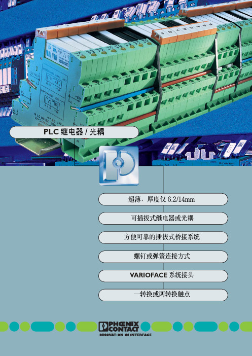
灵活 性意味 着根据 应用场 合既 可以为 每 个通道 自由选 择输入电 压,也可以 装入不 同 的机电式继 电器或者半导 体继电器 (光电 耦 合器) 。固 定的可编程控制 器插件板在这 方 面也是 望尘莫 及。灵活性 也意味着 系统可 以 随时 扩展,并且 可以随 时方便、便 宜地更 换 可插拔式继电器和光电耦合器。
PLC 接口 带回拉式弹簧连接 由 底座接线端子 PLC-BSP…/21 和 可插拔微型继电器组成, 用于安装在 3 上
输入电压 UN
12VDC 24VDC 24VAC/DC 48VDC 60VDC 120VAC/110VDC 230VAC/220VDC2)
12VDC 24VDC 24VAC/DC 48VDC 60VDC 120VAC/110VDC 230VAC/220VDC2)
VARIOFACE 系统接头
(164,)2 mm
可插拔继电器 和光电耦合器,
6.2/14mm
插拔式桥接系统
两个转换 触点 传感器型 执行器型 通用型
按实际应用优化的 系列产品
I
250VAC/6A(10A)
可选用螺钉连接或者回拉式 弹簧连接两种形式
U 通断容量高
一体化集成输入电路 和保护电路
DINVDE0106-101
执行 器 (例如 电磁阀、接 触器等)的 所 有连接线 (包括回线) 都被直接连接在 PLC 执行器接口上。
传感 器 (例 如接 近开 关、限位 开关 等) 的所有连 接线 (包括开 关的供电)都直 接在 PLC 接口上有相应的连接位置。与传统的耦 合元 件相比,可以 节省两 个输出 接线端子 或 者馈 入连接端 子,同时节 省了中 间接线工 作 和宝贵的开关柜空间。
PHOENIX CONTACT 一号电源电路保护器说明书
1DescriptionPrimary-switched power supply with SFB technology, 1 AC, output current 15 AQUINT-PS/ 1AC/12DC/15© PHOENIX CONTACT - 03/2009Data sheet INTERFACE QUINT POWER power supply units – highest system availability due to SFB technologyCompact power supply units of the new QUINT POWER generation maximize the availability of your system. Even the standard power circuit-breakers can be tripped reliably and quickly with the SFB technology (Selective Fusebreaking Technology) and six times the nominal current for 12 ms. Defective current paths are disconnected selectively, the defect is limited and the important system parts remain in operation. A comprehensive diagnostics is carried out by continuously monitoring the output voltage and current. This preventive function monitoring visualizes the criticaloperating modes and reports them to the control unit before an error occurs.–Quick tripping of standard power circuit breakers with dynamic SFB technology power reserve–Reliable starting of difficult loads with static POWER BOOST power reserve–Preventive function monitoring –Can be used worldwide–High degree of operational safety due to high MTBF > 500 000 h, long mains buffering times > 20 ms, high dielectric strength up to 300 V AC103382_en_01Features2Table of contents1Description (1)2Table of contents (2)3Ordering data (3)4Technical data (3)5Structure (6)6Block diagram (7)7Safety notes (7)8Installation (8)9Installation position (8)10Mounting on DIN rails (9)Slim-style installation (9)Low-profile installation (9)11Connection to various systems (10)12Input (11)Protection of the primary side (11)Recommended backup fuse for mains protection (11)13Output (11)Protection of the secondary side (11)14Signaling (12)Floating contact (12)Active signal outputs (13)Signal loop (13)15Function (14)Output characteristic curve (14)Thermal behavior (14)Parallel operation (15)Redundant operation (15)Increased performance (15)Description TypeOrder No.Pcs. / Pkt.Primary-switched power supply with SFB technology, 1 AC, output current 15 AQUINT-PS/ 1AC/12DC/1528667181AccessoriesTypeOrder No.Pcs. / Pkt.Assembly adapter for QUINT POWER 10A on S7-300 rail QUINT-PS-ADAPTERS7/229382061Universal wall adapterUWA 182/5229382351Input dataInput nominal voltage range 100 V AC ... 240 V AC AC input voltage range 85 V AC ... 264 V AC Short-term input voltage 300 V ACDC input voltage range 90 V DC ... 350 V DC AC frequency range 45 Hz ... 65 Hz DC frequency range 0 HzCurrent consumption Approx. 1.9 A (120 V AC)Approx. 0.9 A (230 V AC)Inrush current limitation < 15 A (typical)I 2t< 1.5 A 2sPower failure bypass > 65 ms (120 V AC)> 65 ms (230 V AC)Typical response time < 0.5 sProtective circuitry Transient surge protection Varistor Input fuse, integrated6.3 A (slow-blow, internal)Recommended backup fuse for mains protection 10 A16 A (characteristic B)Discharge current to PE< 3.5 mAOutput dataNominal output voltage12 V DC ±1%Setting range of the output voltage 5 V DC ... 18 V DC (> 12 V constant capacity)Output current15 A (-25°C ... 70°C)16 A (with POWER BOOST, -25°C ... 40°C permanent)60 A (with SFB technology, 12 ms)Derating From +60°C 2.5% per KelvinControl deviation< 1 % (change in load, static 10% ... 90%)< 2 % (change in load, dynamic 10% ... 90%)< 0.1 % (change in input voltage ±10%)Power loss nominal load max.21 W Maximum power dissipation idling 5 WEfficiency > 89 % (for 230 V AC and nominal values)Ascent time < 0.5 msResidual ripple< 10 mV PP (with nominal values)Peak switching voltages 40 mV PPConnection in parallel Yes, for redundancy and increased capacity Connection in seriesYesSurge protection against internal surge voltages Yes, limited to approx. 25 V DC Resistance to reverse feedMax. 25 V DC3Ordering data4Technical dataDC OK activeOutput description U OUT > 0.9 x U N: High signalVoltage+ 5 V DC ... 12 V DCCurrent≤ 20 mA (short circuit resistant)Status display"DC OK" LED green / U OUT < 0.9 x U N: LED flashing DC OK floatingOutput description Relay contact, U OUT > 0.9 x U N: Contact closed Voltage≤ 30 V AC/DC (≤ 0.5 A / at 60 V AC/DC)Current≤ 1 AStatus display"DC OK" LED green / U OUT < 0.9 x U N: LED flashing POWER BOOST, activeOutput description I OUT < I N: High signalVoltage+ 5 V DC ... 12 V DCCurrent≤ 20 mA (short circuit resistant)Status display LED "BOOST", yellow / I OUT > I N: LED onGeneral dataInsulation voltage input/output 4 kV AC (type test)2 kV AC (routine test)Insulation voltage input / PE 3.5 kV AC (type test)2 kV AC (routine test)Insulation voltage output / PE500 V DC (routine test)Degree of protection IP20Class of protection I, with PE connectionMTBF> 500 000 h in acc. with IEC 61709 (SN 29500) Housing material Steel sheet, zinc-platedDimensions W / H / D (state of delivery)60 mm / 130 mm / 125 mmDimensions W / H / D (90° turned)122 mm / 130 mm / 63 mmWeight 1.1 kgAmbient conditionsAmbient temperature (operation)-25 °C ... 70 °C (> 60°C derating)Ambient temperature (storage/transport)-40 °C ... 85 °CMax. permissible relative humidity (operation)95 % (at 25°C, no condensation)Vibration (operation)< 15 Hz, amplitude ±2.5 mm in acc. with IEC 60068-2-615 Hz ... 150 Hz, 2.3g, 90 min.Shock30g in all directions in acc. with IEC 60068-2-27 Pollution degree in acc. with EN 501782Climatic class3K3 (in acc. with EN 60721)StandardsElectrical Equipment for Machinery EN 60204Safety transformers for power supply units IEC 61558-2-17Electrical safety (of information technology equipment)IEC 60950/VDE 0805 (SELV)Electronic equipment for use in electrical power installations EN 50178/VDE 0160 (PELV)SELV IEC 60950 (SELV) and EN 60204 (PELV)Safe isolation DIN VDE 0100-410DIN VDE 0106-1010Protection against electric shock DIN 57100-410Protection against electric shock, basic requirements for safe isolation inDIN VDE 0106-101electrical equipmentStandards (Continued)Limitation of mains harmonic currents EN 61000-3-2Device safety GS (tested safety)Network variants (undervoltage)Semi F47-200Certificate CB SchemeApprovalsUL approvals UL Listed UL 508UL/C-UL Recognized UL 60950Conformance with EMC guideline 2004/108/EC and for low-voltage guideline 2006/95/ECNoise immunity according to EN 61000-6-2Electrostatic discharge EN 61000-4-2Housing Level 4Contact discharge8 kVDischarge in air15 kVComments Criterion BElectromagnetic HF field EN 61000-4-3Housing Level 4Frequency range80 MHz ... 1000 MHzField intensity20 V/mComments Criterion AFast transients (burst)EN 61000-4-4Input 4 kV (level 4 - asymmetrical)Output 2 kV (level 1 - asymmetrical)Signal 1 kV (level 1 - asymmetrical)Comments Criterion BSurge current loads (surge)EN 61000-4-5Input 4 kV (inst. class 4 - asymmetrical: conductor to ground)2 kV (inst. class 4 -symmetrical: conductor to conductor)Output 2 kV (level 3 - asymmetrical: conductor to ground)1 kV (level 1 - symmetrical: conductor to conductor)Signal 1 kV (level 3 - asymmetrical: conductor to ground)Comments Criterion BConducted interference EN 61000-4-6Input/Output/Signal Level 3 - asymmetricalFrequency range0.15 MHz ... 80 MHzVoltage10 VComments Criterion AVoltage dips EN 61000-4-11Input(mains buffering > 20 ms)Comments Criterion BEmitted interference in acc. with EN 61000-6-3Radio interference voltage in acc. with EN 55011EN 55011 (EN 55022) Class B, area of application: Industry and residential Emitted radio interference in acc. with EN 55011EN 55011 (EN 55022) Class B, area of application: Industry and residential5Structure1AC input2DC output3POWER BOOST switching output, active4DC OK switching output active5DC OK output, floating6Potentiometer 5 V DC ... 18 V DC7"DC OK" LED8"BOOST" LED9Universal DIN rail adapter UTA 107/30[mm2]AWG[Nm]solid stranded TorqueInput0.2-2.50.2-2.516-120.5-0.6Output0.2-2.50.2-2.516-120.5-0.6Signal0.2-2.50.2-2.516-120.5-0.6Input dataInput nominal voltage range100 V AC ... 240 V ACAC input voltage range85 V AC ... 264 V ACShort-term input voltage300 V ACDC input voltage range90 V DC ... 350 V DCAC frequency range45 Hz ... 65 HzDC frequency range0 HzInput fuse, integrated 6.3 A (slow-blow, internal)Recommended backup fuse for mains protection10 A16 A (characteristic B)Type of connection Pluggable screw connectionStripping length7 mmOutput dataNominal output voltage12 V DC ±1%Setting range of the output voltage 5 V DC ... 18 V DC (> 12 V constant capacity)Output current15 A (-25°C ... 70°C)16 A (with POWER BOOST, -25°C ... 40°C permanent)60 A (with SFB technology, 12 ms)Type of connection Pluggable screw connectionStripping length7 mm6Block diagram7Safety notes8InstallationThe power supply unit can be snapped onto allDIN rails in acc. with EN 60715. They must bemounted horizontally (connecting terminalblocks top and bottom).9Installation positionSlim-style installation: Installation depth 125 mm (+ DIN rail)(state at delivery)Low-profile installation: Installation depth 63 mm (+ DIN rail)10Mounting on DIN railsSlim-style installationAssembly:Position the module with the DIN rail guide on the upper edgeof the DIN rail, and snap it in with a downward motion.Removing:Pull the snap lever open with the aid of a screwdriver and slidethe module out at the lower edge of the DIN rail.Low-profile installationLow-profile installation can be achieved by mounting the device at right-angles to the DIN rail. Mount the DIN rail adapter (UTA 107/30) as described in the figure. No additional mounting material is required. Fixing screws: Torx T10 (torque 0.8 Nm ... 0.9 Nm).11Connection to various systemsThe connection for 100V AC ... 240 V AC is established using the L, N, and P screw connections.The device can be connected to 1-phase AC networks or to two of the phase conductors of three-phase systems (TN, TT or IT systems in accordance with VDE 0100-300/IEC 60364-3) with nominal voltages of 100 V AC ... 240 V AC.The device also continues to work on short-term input voltages >300V AC.12InputProtection of the primary sideThe device must be installed in acc. with the regulations as inEN 60950. It must be possible to disconnect the device usinga suitable isolating facility outside the power supply.The primary side line protection, for example, is suitable. Fordevice protection, there is an internal fuse. Additional deviceprotection is not necessary.Recommended backup fuse for mains protectionPower circuit breaker 10 A or 16 A, characteristic B (oridentical function). In DC applications, a suitable fuse must bewired in upstream.13OutputThe connection is established using screw connections onthe screw connection of the DC output:12 V DC: "+" and "–"; DC OK switching output active: "DC OK"and "–"; DC OK output floating: "13" and "14"; POWERBOOST switching output active: "I < I N" and "–".The set output voltage is 12 V DC at the time of delivery. Theoutput voltage can be set on the potentiometer.Protection of the secondary sideThe device is electronically protected against short circuit andidling. In the event of a malfunction, the output voltage islimited to 25 V DC.14SignalingThe active signal output, the floating signal contact and the active POWER BOOST switching output are provided for function monitoring. The DC OK-LED and the BOOST-LED also enable the function evaluation of the power supply unit directly on the operation site (refer to the output characteristic curve).I < I N I > I N U OUT < 0.9 x U N"DC OK" LED ON ON Flashing"BOOST" LED OFF ON ONActive DC OK switchingoutputON ON OFFFloating DC OK output Closed Closed OpenActive POWER BOOSTswitching outputON OFF OFFMeaning Normal operation of thepower supply POWER BOOST operation,e.g. to start loadsOverload mode, e.g.consumer short circuit oroverloadFloating contactThe floating signal contact opens and indicates that the set output voltage has undershot by more than 10%. Signals and ohmic loads of up to maximum 30V and currents of maximum 1A (or maximum 60V with maximum 0.5A) can be switched. For heavily inductive loads such as a relay, a suitable protection circuit (e.g. damping diode) is necessary.Active signal outputsThe 5 ... 12 V DC signal is applied between the "DC OK" and the "–" connection terminal blocks or between "I < I N" and "–" and can carry up to 20 mA. By switching from "active high" to "low", the DC OK signal output signalizes when the output voltage is fallen short of by more than 10%.The DC OK signal is decoupled from the power output. It is thus not possible for devices connected in parallel to act as an external power supply.The 5 ... 12 V DC signal can be directly connected to a logic input for evaluation.The POWER BOOST signal output signalizes that the nominal current is exceeded.Signal loopMonitoring two devices: Use the active signal output of device 1 and loop in the floating signal output of device 2. In the event of malfunctioning, a common alarm is output. Any number of devices can be looped in. This signal combination saves wiring costs and logic inputs.15FunctionOutput characteristic curveThe power supply unit operates with the static POWER BOOST power reserve as per the U/I characteristic curve given in the figure. In case of ambient temperaturesT amb<+40°C,I BOOST is available permanently; it is available only for a few minutes in case of higher temperatures. In the event of a secondary short circuit and overload, the output current is limited to I BOOST. Thereby, the module does not switch off, but supplies a continuous output current. The secondary voltage is reduced until the short circuit has been remedied. The U/I characteristic curve with the POWER BOOST power reserve ensures that high inrush currents of capacitive loads and of consumers with DC/DC converters in the input circuit can be fed reliably.In order to trip the standard power circuit breakers magnetically and thus very quickly, QUINT POWER supplies six times the nominal current for 12ms with the help of the SFB technology. The defective current path is switched off using this dynamic power reserve; consumers connected in parallel continue to operate without an interruption. The error is thus restricted and the important system parts continue to operate.The characteristic curve shows when I<IN, I>I N andU<0.9x U N. The relevant signaling is given in the table.U N = 12 VI N = 15 AI BOOST = 16 ASFB technology = 60 AP N = 180 WP BOOST = 192 WThermal behaviorWith an ambient temperature of up to +40°C, the device supplies the continuous output current of I BOOST. The device can supply a nominal output current of I N with ambient temperatures of up to +60°C. In the case of ambient temperatures above +60°C, the output current must be reduced by 2.5% per Kelvin increase in temperature. The device does not switch off at ambient temperatures of +70°C or thermal overload. The output capacity is reduced as far as necessary to provide device protection. After it has cooled down, the output capacity is increased again.Parallel operationDevices of the same type can be connected in parallel to enable both redundancy and an increase in efficiency. No other alignment is necessary when in the state of delivery.If the output voltage is adjusted, a uniform distribution of power is guaranteed by setting all parallel operated power supply units to exactly the same output voltage.To ensure symmetrical distribution of power, we recommend designing all cable connections from the power supply unit to a busbar of the same length and with the same conductor cross section. The system makes it advisable to install a protective circuit at the output of each device when more than two power supply units are connected in parallel (e.g. decoupling diode or DC fuse). This prevents high reverse feed currents in the event of a secondary device fault.Redundant operationRedundant circuits are suitable for the supply of systems which make especially high requirements on the operational safety. If a fault occurs in the primary circuit of the first power supply unit, the second device automatically takes over the entire power supply, without interruption, and vice versa. For this reason, the power supply units to be connected in parallel are dimensioned in such a way that the total current requirement of all consumers can be completely covered by one power supply unit. 100% redundancy makes external decoupling diodes necessary (QUINT-DIODE/40, Order No. 2938963)!Increased performanceFor n parallel connected devices, the output current can be increased to n x I N. Parallel connection to increase efficiency is used for the expansion of existing systems. It is advisable to use parallel connection if the power supply unit does not cover the current requirement of the most powerful consumer. Otherwise the consumers should be spread among individual devices independent of one another. A maximum of five devices can be connected in parallel!。
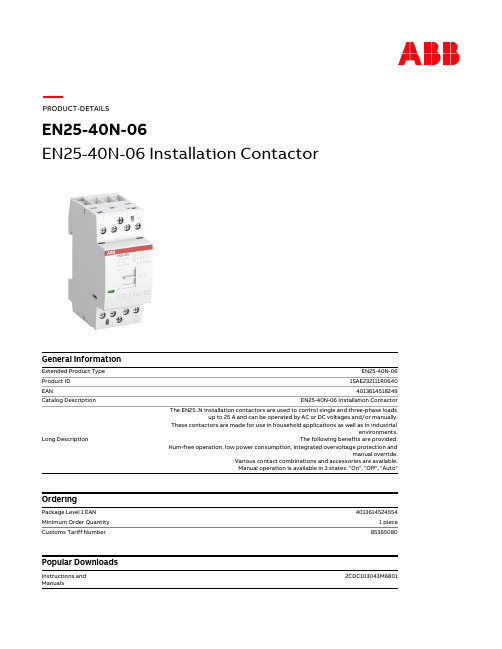
EN25-40N-06 安装接触器说明书
1SAA920001-1202 1SAA920000-0705 1SAD938503-0302
1 piece 39 mm 92 mm 69.5 mm
0.24 kg
4013614524554 60 piece 280 mm 210 mm 395 mm
Manual operation is available in 3 states: "On", "Off", "Auto"
4013614524554 1 piece
85365080
2CDC103043M6801
EN25-40N-06
Dimensions
Product Net Width Product Net Height Product Net Depth / Length Product Net Weight
(NO) 25 A
(230 V) Single Phase, NO 5.8 kW (400 V) Three Phase, NO 17.3 kW
(230 V) Single Phase, NO 9 A (400 V) Three Phase, NO 9 A (230 V) Single Phase, NO 1.3 kW (400 V) Three Phase, NO 4 kW
3
AC-3 (NO) 500000 cycle AC-7a (NO) 130000 cycle AC-7b (NO) 500000 cycle
1000000 cycle 4 0
4
2
3 IEC/EN 60947-1 IEC/EN 60947-4-1
电气知识--接触器、继电器、变频器
电气基础知识接触器科技名词定义中文名称:接触器英文名称:contactor定义:能频繁关合、承载和开断正常电流及规定的过载电流的开断和关合装置。
所属学科:电力(一级学科);配电与用电(二级学科)本内容由全国科学技术名词审定委员会审定公布接触器接触器(Contactor)是指工业电中利用线圈流过电流产生磁场,使触头闭合,以达到控制负载的电器。
接触器由电磁系统(铁心,静铁心,电磁线圈)触头系统(常开触头和常闭触头)和灭弧装置组成。
其原理是当接触器的电磁线圈通电后,会产生很强的磁场,使静铁心产生电磁吸力吸引衔铁,并带动触头动作:常闭触头断开;常开触头闭合,两者是联动的。
当线圈断电时,电磁吸力消失,衔铁在释放弹簧的作用下释放,使触头复原:常闭触头闭合;常开触头断开。
目录分类结构说明接触器与继电器的区别技术发展接触器的触头接触不牢靠的原因及处理方法简介分类结构说明接触器与继电器的区别技术发展接触器的触头接触不牢靠的原因及处理方法展开简介在电工学上,因为可快速切断交流与直流主回路和可频繁地接通与大电流控制(某些型别可达800安培)电路的装置,所以经常运用于电动机做为控制对象﹐也可用作控制工厂设备﹑电热器﹑工作母机和各样电力机组等电力负载,接触器不仅能接通和切断电路,而且还具有低电压释放保护作用。
接触器控制容量大,适用于频繁操作和远距离控制。
是自动控制系统中的重要元件之一。
在工业电气中,接触器的型号很多,电流在5A-1000A的不等,其用处相当广泛。
海关HS编码:85364100(主电路电压<=60V的接触器),85364900(60V<主电路电压<=1000V的接触器),85353000(主电路电压>1000V的接触器)分类通用接触器可大致分以下两类。
1交流接触器。
主要有电磁机构。
触头系统。
灭弧装置等组成。
常用的是CJ10。
CJ12。
CJ12B等系列。
2直流接触器,一般用于控制直流电器设备,线圈中通以直流电,直流接触器的动作原理和结构基本上与交流接触器是相同的。
uk端子选型
V0
认证数据 (UL 和 CSA/CUL) 额定工作电压 / 额定工作电流 / 导线线号
UL: [V] / [A] / AWG
300 / 15 / 30 - 14
CSA/CUL: [V] / [A] / AWG
300 / 15 / 30 - 14
52 Phoenix Contact
端子厚度 6.2 (IEC)
所有 带标记 安装槽的 菲尼克 斯电气组 合 端子 都可以既 经济迅速 又完美地 用标记 系统 ZB…加以标记。参见样本第 148 页有关标识 材料的详细介绍。
可 将 10 位的 带绝缘 套头的 固定桥 接件 FBI 剪成所需的任意低位数,装入端子外壳并 用螺钉紧固。
固定桥接件 FBRI 的槽梁条带螺钉,螺钉 上 带非易失 的定距 小套筒。这 种桥接件 的位 数为 2 至 10 位。
I
U
AWG [A] [V]
24-12 32 800 24-12 28/22 750
u C I CCA b P F BV/LR/NV/PRS/RS/NK X KEMA f u FTZU/KDB
型号
UK 3 N UK 3 N BU UK 3 N RD
订货号
30 01 50 1 30 01 51 4 07 19 13 9
利用短路插头 KSS 可实现两个或多个带 有测试插孔座的相邻端子的短路。
分组隔板 ATP 超出端子条的轮廓挺然而 出,因而可实现清晰的分组。
Phoenix Contact 51
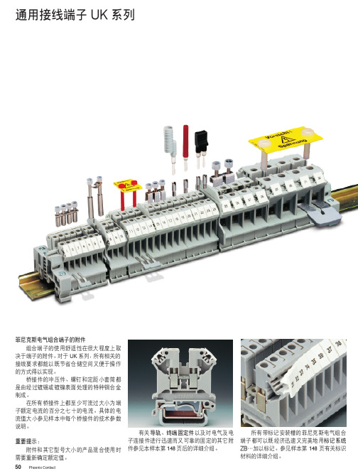
通用型接线端子 UK 系列
19
6
10
7
45
2
11
8
UK 1.5 N
3
通用型接线端子 UK... 系列产品具有下列 对于实际应用很有意义的典型特征:
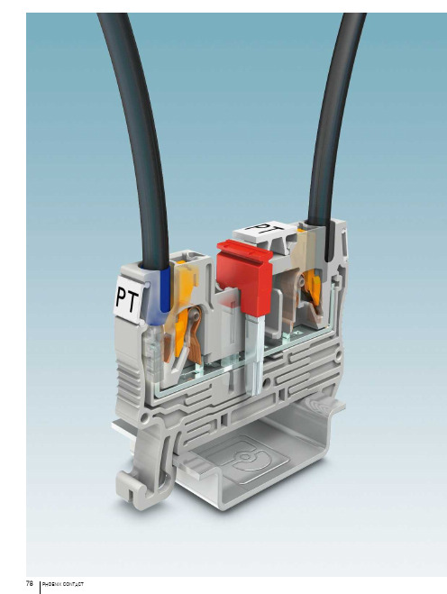
2菲尼克斯接线端子 PT系列
产品一览
1.5 mm² 直通式多导线多层接线端子和接地端子
传感器/执行器端子 刀闸端子 PTRV高密度矩阵接线单元 PTMC高密度矩阵接线单元 斜面式接线端子 微型直通式接线端子和接地端子
2.5 mm² 直通式多导线多层接线端子和接地端子
分断端子和刀闸端子 二极管端子 单侧螺钉连接的混合端子
斜面式接线端子 斜面式分断端子和刀闸端子 建筑安装端子 微型直通式接线端子和接地端子
PTPOWER Power-Turn大电流接线端 子
接线端子——CLIPLINE complete
PT直插式接线端子 马达接线端子
– 微型接线端子,用于15 mm DIN导轨 系统
– 超薄设计,用于小型接线盒 – 每条电流通路均提供测试通道 – 可使用专利的FBS ... 桥接件系统进行
桥接 – 接地端子外形相同 – 插拔式端子,一侧采用 COMBI 插拔式
– 接线位和工作区域标识清晰,可防止 接线错误
– 多种工具可选,可满足各种操作 – 使用双桥接井进行电位分配 – 每条电流通路均提供单独的测试通道
– 用于传感器执行器布线,宽度仅 3.5 mm,节省空间
– 紧凑型设计,实现高密度信号布线 – 馈电模块可通过FBS桥接件对正负电
位进行单独分配 – 带LED显示的型号可显示开关状态 – 接线层采用大标识区域
[mm²] AWG
单根导线 两根带 TWIN 冷压头的柔性导线 直接插拔式连接横截面 一般参数 剥线长度 绝缘材料 阻燃等级,符合UL 94 注意:该产品的其它数据信息可查询相关文档。
[mm²] [mm²] [mm²]
[mm]
IEC 60947-7-1/IEC 60947-7-2
1.5
菲尼克斯接线端子资料

德国菲尼克斯电气集团专为电力、通讯、交通、铁路运输、石油化工及工业自动化等行业提供世界一流产品和优良服务,是世界顶尖级电连接专业厂家。
目前在海外32个国家设有子公司,56个国家设有销售处和代表处。
1993年底,德国菲尼克斯电气集团与南京电力自动化研究院(NARI南瑞集团)合资组建了南京菲尼克斯电气有限公司,主要生产并经营菲尼克斯集团各种高质量的电连接件、电子模块、信号变送器、现场总线、防雷浪涌电压保护系统等产品。
南京菲尼克斯电气公司的成立不仅进一步巩固了菲尼克斯产品在电连接行业的领先地位,同时也为中国引进了更多具有世界先进水平的工业自动化产品,有力地促进了国内电气连接及工业自动化技术的发展。
公司自1993年组建以来,仅用三年时间,市场占有率即跃居全国电气接口行业首位。
截止2001年,南京菲尼克斯的业务量已达2亿元,先后在全国各地设立了12个代表处,拥有60多家分销商和经销商。
南京菲尼克斯的迅速崛起,在社会各界引起了较大的反响。
1997年以来公司连续几年被评为江苏省重点外商投资企业、江苏省“AAA”级资信企业、南京市高利税企业、江苏省及南京市外商投资先进企业、南京市三资企业管理工作先进单位、国家级高新技术产业开发区“作出突出贡献企业”。
1999年公司顺利通过ISO9002质量体系认证;2002年公司又顺利通过ISO2000质量体系认证。
德国菲尼克斯集团总部非常看好中国市场,从1996年起多次追加投资,引进各种现代化生产设备,并在南京江宁开发区征地120亩,着手建立其海外最大的生产管理基地——一个具备研发中心的菲尼克斯工业园,为中国用户提供更优质的产品,更完善的服务。
到目前为止,总投资近三千万美元的一家合资公司、两家独资公司已在华成立,中国公司已成为面向中国及亚太地区颇具规模的海外生产基地。
位于南京江宁开发区的公司总部目录PHOENIX CONTACT3。
Phoenix Contact REG-K 12x230 16 手动模式下的开关器 说明书

The switch actuator REG-K/12x230/16 with manual mode (referred to below as the actuator ) can switch twelve loads via separate, floating make contacts.Y ou can also manually switch the connected loads with manual switches on the actuator without bus voltage.The actuator has a bus coupler. It is installed on a DIN rail, with the bus connection made via a bus connecting terminal. It is supplied with power from the bus voltage. A data rail is not required.For your safetyHAZARD OF ELECTRIC SHOCK, EXPLOSION, OR ARC FLASHSafe electrical installation must be carried out only by skilled professionals. Skilled professionals must prove profound knowledge in the following areas:•Connecting to installation networks •Connecting several electrical devices •Laying electric cables•Connecting and establishing KNX networks •Safety standards, local wiring rules and regulations Failure to follow these instructions will result in death or serious injury.RISK OF FATAL INJURY FROM ELECTRIC SHOCK The output may carry electrical current even when the load is switched off.•When working on the device: Always disconnect the device from the supply by means of the fuse in the in-coming circuit.•Even if the manual switch is in the …OFF“ position, aKNX telegram can switch the connections to being live at any time. Before working on the device, always diconnect the fuse in the incoming circuit from the supply.Failure to follow these instructions will result in death or serious injury.Getting to know the switch actuatorA Bus connecting terminal, max. 4 core pairsB Programming LED (red LED)C Programming buttonD Cable coverE Operating LED (green LED)F Manual switchG Screw terminals1Set the actuator onto the DIN rail.2Connect KNX.¼WARNINGRisk of fatal injury from electrical current. The device could become damaged.Safety clearance must be guaranteed inaccordance with IEC 60664-1. There must be at least 4 mm between the individual cores of the 230 V supply cable and the KNX line.Connections, displays and operatingelementsMounting the actuatorRISK OF FATAL INJURY FROM ELECTRIC SHOCKVoltage may be present at the outputs when the mains voltage is connected to the system.If subjected to strong vibrations during transportation, the switch contacts might change to the enabled state.After connecting the bus voltage, set the relays of the channels to the position desired simply by switching …On/Off“ or by changing the manual switch to …OFF“.Failure to follow these instructions will result indeath or serious injury.3Connect the bus voltage.4Switch the relays of the channels on and offmanually once with the manual switches.5Connect the load.The cables to the loads as well as the system voltages (L1, L2 or L3) are connected via screw terminals for max. 16 A. Every two L connections are bridged internally.6Connect the mains voltage.Now you can check the functionality of the actuator and the connected loads without having to load the application from the ETS. (See the "Operating the actuator" section.)1Press the programming button.The programming LED lights up.2Load the physical address and application into thedevice from the ETS.The programming LED goes out.The operating LED lights up: The application was loaded successfully, the device is ready for operation.Putting the actuator into operationSpaceLogic KNXSwitch actuator REG-K/12x230/16 with manual modeOperating instructionsArt. no. MTN648493Normally, you control connected devices using push-buttons or by remote control. However, you canmanually switch each of the actuator's channels on and off directly at the manual switches.Schneider Electric Industries SAS 35 rue Joseph Monier Rueil Malmaison 92500 FranceIf you have technical questions, please contact the Cus-tomer Care Centre in your /contactOperating the actuatorT echnical dataExternal auxiliary voltage:NonePower supply from bus:DC 24V/max. 10mA Insulation voltage:AC 4 kV between bus and 230V ACSwitch contacts:12 x make contacts, floating Nominal voltage:AC 230V , 50 to 60Hz Nominal current:16A, cos ϕ = 0.6Connected loadIncandescent lamps:AC 230V , max. 3600W with 10,000 switching cyclesHalogen lamps:AC 230 V , max. 2500 W with 10,000 switching cycles Fluorescent lamps:AC 230V , max. 2500VA, parallel-compensated,with 5,000 switching cycles Capacitive load:AC 230V , 16A max. 200μF with 5,000 switching cycles Minimum loads:≥ 24V DC, 100mASwitching frequency:max. 10 per minute at nominal loadAmbient temperature Operation:-5°C to +45°C Storage:-25°C to +55°C Transport:-25°C to +70°CEnvironment:The device is designed for use at a height of up to 2000m above sea level (MSL).Max. humidity:93%, no moisture condensationOperating elements:Programming button,twelve manual switches for manual operationDisplay elements:Red LED for programming check,green LED to indicate device availabilityConnections Bus:via two 1 mm pins for bus connecting terminal Outer conductor:eleven 3-gang screwterminals (1–11) and one 2-gang screw terminal (12) for each max. 2.5mm 2Installation width:12depth units = approx. 216mmEC guidelines:Corresponds to Low-Voltage guideline 73/23/EEC and EMC guideline 89/336/EECSchneider Electric -ContactSchneider Electric Limited Telford, TF3 3 BL, UKUK RepresentativeStafford Park 5V 6484-562-02 11/21。
- 1、下载文档前请自行甄别文档内容的完整性,平台不提供额外的编辑、内容补充、找答案等附加服务。
- 2、"仅部分预览"的文档,不可在线预览部分如存在完整性等问题,可反馈申请退款(可完整预览的文档不适用该条件!)。
- 3、如文档侵犯您的权益,请联系客服反馈,我们会尽快为您处理(人工客服工作时间:9:00-18:30)。
故障 双金属片功能
引起的原因 马达电流大于设定值(如 等级 10A) 需要冷却时间!(20 分钟) 故障发生在反转时 故障发生在正转时 (过电流导致) “L”或“R”2 分钟后闪烁: 此时可手动复位。 故障发生在反转时 故障发生在正转时 (正转和反转的信号同时为 1 导致)
LED:PWR ERR L R 确认方式
3.11kW(4.23HP) 6.22kW(8.47HP) 0mA 500mV 100A(t=10ms) 550V AC 变阻器
单触点,1 PDT
银合金,硬镀金
30V AC/36V DC (250V AC/DC)
4.3.1. 故障确认 故障确认有 3 种方式: 手动(复位按钮):通过按模块面板上的复位按钮(Reset)进行确认。 如果按住复位按钮超过 2s,该固态换向接触器会重回到故障状态;如果确认(即按住复位按钮) 超过 6s,模块会对输出侧功率进行测试,然后进入“参数设置”模式。 手动(远程确认):可以在端子 MAN(2.1)和 RES(2.2)之间接入一个常开触点(N/O),如一 个按钮,进行远程故障确认。但如果在 2s 后该触点还是闭合的,固态换向接触器会重新回到故 障状态。 自动:如果在端子 RES(2.2)和 AUTO(2.3)之间有接线,当双金属片功能回复后就会自动复
固态换向接触器 ELR W3-…/500AC-…I
1. 简介 3 相固态换向接触器 ELR W3-…/500AC-…I,带电流监视,组合了以下 4 种功能: ·右转接触器 ·左转接触器 ·马达保护热继电器 ·急停接触器(等级最高为 3)。 由于模块内部已经完成了大部分联锁回路的接线和负载接线,所以接线的工作量很少。 2. 安全条例/安装指导 ·使用模块时,请先了解国家安全规范和事故防止条例。 ·忽视安全规范将导致死亡、严重伤害或事故! ·只有经验丰富的电气工程师才能对该模块进行启动、组装、修改工作。 ·对模块进行改动前,请先断开这个模块的电源。 ·当模块用 230V AC 供电时,要保证该相电源同时用于左转和右转的控制。 ·有急停需求时,高层的控制单元要保证不会自动重启设备! ·工作时,齿轮箱的部分会承受高电压! ·工作时,齿轮箱的保护盖不能被拿掉! ·不要扔掉操作说明书!
20A TRS20R20A (保险丝)- 短路(5 kA 网络)
25A gl-gG (保险丝)- 短路(10 kA 网络)
·相应的控制电压和控制电压输入必须采用符合 DIN 19240 标准的电源模块(最大 5%残压)!
用 230V AC 控制的模块,必须保证该相电压也用于负载。 ·使用长控制导线时,为了避免容性或感性耦合导致干扰脉冲,建议使用屏蔽电缆。
2297057
ELR W3-230AC/500AC-2I
2297044
ELR W3-230AC/500AC-9I
2297060
ELR W3-24DC/…
ELR W3-230AC/…
UN=24V DC
UN=230V AC
19.2…30V DC
85…253V AC
(32V DC,最多 1 分钟)
40mA
5.3. 马达保护 使用固态换向接触器来进行马达保护功能被设计的尽可能简单:和安全性有关的功能仅通过固 态换向接触器实现,没有任何外在的影响,不需要特殊的开关技巧。
5.4. 带刹车的马达 如果和模块相连的是带刹车的马达(接线在马达接线盒内),刹车必须接到 2/T1 和 6/T3(400V AC)。如果是 230V AC 的刹车,必须接到 4/T2 和星型点。 请注意以下事项: 采用刹车后马达的监视电流值要增加(刹车的标称电流),要重设固态换向接触器的相应设置 (请参见第 4.2 点)。
IN 时的残压
小于
电涌电流
输出侧保护回路
继电器报警输出
触点类型
触点材料
最大开关电压
最小开关电压
极限持续电流
最小开关电流
最大额定功率,纯阻性负载
24V DC
48V DC
60V DC
110V DC
220V DC
250V AC
ELR W3-24DC/500AC-2I
2297031
ELR W3-24DC/500AC-9I
然而,这种要把正在运行的马达的控制电源切掉的要求总是会导致固态换向接触器产生 磨损,所以,如果在系统的整个使用期内,如果断开次数不多于 10000 次,必须使用 2 个控制 回路!
5.2. 安全门(急停和紧急断开) 图 5 和图 6 所示回路用于安全的停止某个工作状态,如安全门或双手控制。 这种情况下,切掉的不是模块的供电,而是模块的控制回路,可使用单通道,也可使用双通道。 出于这个目的,采用安全继电器给模块的左转或右转信号供电。
相位故障
被测量的 2 相马达电流中有 1 个为 0,
或该 2 相马达电流之间的相位差不是 120°,
而是 180°。
锁紧
测量的马达电流超过最大值 1.5s。
故障发生在反转时
故障发生在正转时
说明:
E LED 长亮
B LED 以 2Hz 频率闪烁(50:50)
A LED 熄灭
E B A A 手动
E B B A 手动 E B A B 手动
如果要把 2 根导线接到 1 个接线端子上,必须使用相同线径的导线。
3.2. 接线图
4. 功能 4.1. 工作和工作模式 4.1.1. 状态 LED 该固态换向接触器共有 4 个用于指示工作状态的 LED 灯,LED 的功能是基于 NAMUR 建 议 NE 44。当控制电压加上以后,所有的 LED 灯会亮一次,作为测试。模块的工作状态则通过 1 个绿色的 LED 指示。 外部故障(过程故障:过电流、不对称、相位故障)通过 1 个红色的 LED 指示,这时模块 处于安全非触发状态,需要进行故障确认来退出这个状态。 正转或反转驱动总是通过 1 个黄色的 LED 进行显示。
危险!不要在带电情况下工作!会伤及生命!
·当和 3 相电网相连时,一定要分清接线端子!
·保护:
25A(Diazed)- 最大线径为 2.5mm2 的线路保护
16A FF(6.3 × 32mm)-
设备保护
16A(自动设备 B,断路器)- 短路(1.5 kA 网络)
20A (马达保护开关)- 短路(1.5 kA 网络)
4mA
-3…9.6V DC
<44V AC
19.2…30V DC
85…253V AC
3mA
7mA
ELR…-2I
ELR…-9I
带旁路的安全输出模块,3 相可断开
500V AC
500V AC
42…550V AC
42…550V AC
0.18…2.4A
0.18(1.2)…9.0A
2.4A
9A
2.4A
6.5ª
0.83kW(1.13HP) 1.66kW(2.26HP) 0mA 300mV 100A(t=10ms) 550V AC 变阻器
应用区域: ·回路如果在有爆炸性灰尘的区域 21 和 22 中,必须保证连到回路的设备符合等级 2D 或 3D, 或有类似的认证。 ·这是用于环境 A 的产品,如果用于家庭可能会引起未知的无线问题,这种情况下,使用者有 义务要采取合适的措施来解决这一问题。
3. 接线说明 3.1. 主要接线和线路保护
位。
4.3.2. 反馈 一旦固态换向接触器检测到 1 个故障,故障继电器会被激活(比如常开触点会吸合,而常闭触 点会断开),这种动作和马达保护开关或马达保护继电器的动作相对应。 该故障继电器仅用于信号,而不是安全链路中的一环,所以不包含在安全性观测中。
5. 应用举例 5.1. 急停 把 1 个固态换向接触器加入到急停链路中的最简单的方法请参见图 3,和安全继电器这样接线 的情况下,当急停按下以后,固态换向接触器的供电会被切掉。 当切掉模块的供电后,要保证在 25ms 后能把马达的供电关掉。由于固态换向接触器的电源是 由安全继电器的单个通道切掉的,所以这种安装方式(符合 SIL 3,等级 3,等级 4)只允许在 交错线故障能消除的情况下,且固态换向接触器和安全继电器安装在同一个控制柜中的时候采 用。 如果这种交错线故障消除不被允许,模块的供电必须通过 2 个通道或 2 位进行切除(请参见图 4)。
5.5. 辅助继电器接线 用于启动外部刹车或给 PLC 报警的辅助继电器(如 PLC-RSC-230UC/21/SO46 2980490)必须连 到 4T2 和 N。
6. 技术参数
型号
订货号
输入侧参数 额定控制电压 US 控制电压范围
US 时的额定控制电流(不含反馈)
ቤተ መጻሕፍቲ ባይዱ
控制输入 L、R、MAN、AUT:
“低”切换电平
“高”切换电平
额定电流
输出侧参数
负载侧
回路原则
开关电压
(额定工作电压 Ue)
2℃0 时的负载电流(请参见 6.3. 衰减曲线)
AC 51
按照 EN 60947-4-3
AC 53a
按照 EN 60947-4-3
额定开关容量
双向满负荷(功率因素=0.4)
满负荷(功率因素=0.8)
漏电流(输入,输出)
过电流参数: 电流的实际值和设定值之间的比例。
如果马达电流为 12A 或 45A,会一直监视是否堵转(请参见第 6.1 故障特性)。
4.3. 故障检测 该固态换向接触器有多项诊断功能,不仅能检测很多内部故障,还可检测外部故障(外围设备 故障)。所有的内部故障如果未被确认,会存储在模块中,该模块不能被再次启动。通过 LED 等 来指示工作状态。
E B E A 自动 E B A E 自动
E B B A 手动 E B A B 手动
模块重新上电时 出现故障
错误校验。
EB
双金属片功能的存储器被设到最大值,