Power 750 PowerVM安装配置手册簿
Power-750--PowerVM安装配置手册
异地灾备中心Power 750 PowerVM安装配置手册使用火狐浏览器输入IP地址,显示如下界面:输入HMC默认用户名与密码:hscroot/abc123选中受管服务器,在下拉菜单中,选择更新密码输入HMC默认密码abc123输入ASMI默认密码admin选中受管服务器,下拉菜单>操作>开机开机选项,选择“正常”选择受管服务器,下拉菜单>属性将“关闭所有逻辑分区后关闭系统”选项去掉将受管服务器下的全分区关闭选择立即关闭选择“yes”选择“no”全分区已经关闭,如下图所示:再次选择受管服务器,下拉菜单>属性服务分区选择“未分配”选中受管服务器的全分区,将全分区删除选择“ok”选中受管服务器,下拉菜单>配置>创建分区>AIX or Linux分区名输入“test”概要文件输入“test_profile”选择专有处理器按下图配置CPU按下图配置内存将下列设备添加为“必须”(未完待续)将下列设备添加为“必须”添加后如下图所示:添加后如下图所示:一直单击下一步,直到出现如下画面,单击完成创建后的分区如下图所示:将系统诊断光盘放入光驱中,并激活test分区选择打开终端窗口,并点击高级按钮单击“ok”浏览器弹出如下窗口,选择“始终信任此发行者的内容”,单击是输入“0”后回车系统启动界面如下:服务器需要扫描新硬件,时间比较长,请耐心等待(大约50分钟左右),如下图输入“1”并回车出现如下画面,并回车如下画面,输入“3”并回车输入“vt100”并回车回车后出现如下画面:使用键盘的“向下方向键”移动到如下画面,选择“Raid Array Manager”并回车选择“IBM SAS Disk Array Manager”并回车选择“List SAS Disk Array Configuration”并回车选择“sissas0 Available 00-00 PCI Express x8 Ext Dual-x4 3Gb SAS Adapter”并回车sissas0 与sissas2 两块SAS卡位HA的关系,下面共有5块300GB SAS 硬盘,如下图所示:按住ESC+3 返回,选择“sissas1 Available 01-00 PCI Express x8 Ext Dual-x4 3Gb SAS Adapter”并回车Sissas1 与sissas3 两块SAS卡位HA的关系,下面共有5块300GB SAS 硬盘如下图所示:按ESC+3 返回,选择“Create an Array Candidate pdisk and Format to 528 Byte Sectors”回车选择“sissas0 Available 00-00 PCI Express x8 Ext Dual-x4 3Gb SAS Adapter”并回车,如果出现如下画面按ESC+3 返回,选择与sissas0 同一组的另外一块SAS卡sissas2,如下图所示:按ESC+7 选择全部的5块硬盘回车,如下图所示:出现确认窗口后回车:回车后出现如下画面,此过程时间较长,请耐心等待格式化完成5块硬盘全部格式化完毕后,如下图所示:回车后如下图所示:回车后,选择“sissas1 Available 01-00 PCI Express x8 Ext Dual-x4 3Gb SAS Adapter”回车后如下图所示:按ESC+7键选择所有5块硬盘,如下图所示:出现确认对话框,回车开始格式化磁盘,格式化时间比较长,请耐心等待,如下图所示:格式化完成后如下图所示:回车后如下图所示。
PowerFlex 750-Series Power Jumpers说明书
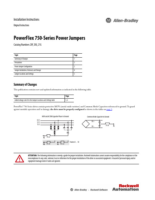
Installation InstructionsOriginal InstructionsPowerFlex 750-Series Power JumpersCatalog Numbers 20F, 20G, 21GSummary of ChangesThis publication contains new and updated information as indicated in the following table.PowerFlex® 750-Series drives contain protective MOVs (metal-oxide varistors) and Common Mode Capacitors referenced to ground. T o guard against unstable operation and/or damage, the drive must be properly configured as shown in the tables on page 3.Topic Page Summary of Changes 1Precautions2Power Jumper Configuration2Jumper Installation, Removal, and Storage 4Jumper Locations and Settings5Topic Page Added voltage code B to the Jumper Locations and Settings table5, 6ATTENTION: The following information is merely a guide for proper installation. Rockwell Automation cannot assume responsibility for the compliance or the noncompliance to any code, national, local or otherwise for the proper installation of this drive or associated equipment. A hazard of personal injury and/or equipment damage exists if codes are ignored.MOV and AC EMI Capacitor Phase to GroundCommon Mode Capacitor to Ground2Rockwell Automation Publication 750-IN011F-EN-P - June 2017PowerFlex 750-Series Power JumpersPrecautionsBefore proceeding, verify that all power to the drive has been removed.Qualified PersonnelPersonal SafetyProduct SafetyPower Jumper ConfigurationATTENTION: Allow only qualified personnel familiar with adjustable frequency AC drives and associated machinery to plan or implement the installation, start-up, and subsequent maintenance of the system. Failure to comply can result in personal injury and/or equipment damage.ATTENTION: To avoid an electric shock hazard, verify that the voltage on the bus capacitors has discharged completely before removing/installing jumpers. Frames 1 (7)Measure the DC bus voltage at the following points (see the PowerFlex 750-Series AC Drive Installation Instructions, publication 750-IN001 for locations):•Measure the DC bus voltage at the power terminal block by measuring between the +DC and -DC terminals or between the +DC and -DC test point sockets if equipped.•Also measure between the +DC terminal or test point and the chassis, and between the -DC terminal or test point and the chassis. The voltage must be zero for all three measurements.Frames 8 (10)Measure the DC bus voltage at the DC+ and DC- TESTPOINT sockets on the front of the power module (see Installation Instructions for location).ATTENTION: This drive contains ESD (Electrostatic Discharge) sensitive parts and assemblies. Static control precautions are required when installing, testing, servicing or repairing this assembly. Component damage can result if ESD control procedures are not followed. If you are not familiar with static controlprocedures, reference an applicable ESD protection guide.ATTENTION: Risk of equipment damage exists. The drive power source type must be accurately determined. Jumpers PE-A, PE-A1, PE-A2, and PE-B must be configured for the power source type according to the recommendations shown in the following table.Rockwell Automation Publication 750-IN011F-EN-P - June 20173PowerFlex 750-Series Power JumpersT o connect or disconnect these devices, refer to pages 5…7.In addition, on an ungrounded distribution system where the line-to-ground voltages on any phase could exceed 125% of the nominal line-to-line voltage, install an isolation transformer. See Wiring and Grounding Guidelines for PWM AC Drives, publication DRIVES-IN001, for more information on impedance grounded and ungrounded systems.Recommended Power Jumper Configurations – Frames 1 (7)Power Source Type Jumper PE-A (1) (2)(MOV / Input Filter Caps)(1)When MOVs are disconnected, the power system must have its own transient protection to maintain known and controlled voltages.(2)Frame 5…7 Common DC Input drives do not have the PE-A jumper.Jumper PE-B(DC Bus Common Mode Caps)Benefits of Correct Configuration on Power Source TypeNon-solid Ground •AC fed ungrounded •Impedance grounded • B phase ground •DC fed from an active converterDisconnected Disconnected Helps avoid severe equipment damage when ground fault occurs.Solid Ground•AC fed solidly grounded•DC fed from passive rectifier, which has a solidly grounded AC sourceConnected ConnectedReduced electrical noise, most stable operation, EMC compliance, reduced voltage stress on components and motor bearings.Recommended Power Jumper Configurations – Frames 8 (10)Power Source TypeJumper PE-A1 (1)(MOV)(1)When MOVs are disconnected, the power system must have its own transient protection to Achieve known and controlled voltages.Jumper PE-A2(Input Filter Caps)Jumper PE-B(DC Bus Common Mode Caps)Benefits of Correct Configuration on Power Source TypeNon-solid Ground •AC fed ungrounded•Impedance grounded• B phase ground•DC fed from an active converter Disconnected Disconnected Disconnected Helps avoid severe equipment damage when ground fault occurs.Solid Ground•AC fed solidly grounded•DC fed from passive rectifier, which has a solidly grounded AC sourceConnected Connected ConnectedReduced electrical noise, most stable operation, EMC compliance, reduced voltage stress on components and motor bearings.IMPORTANTCommon mode capacitors are used to conform with the EMC Directives. Removing these devices can withdraw the associated directive.4Rockwell Automation Publication 750-IN011F-EN-P - June 2017PowerFlex 750-Series Power JumpersJumper Installation, Removal, and StorageJumper screws (Frames 2…5), wires (Frames 1, 6 & 7), or plugs (Frames 8…10) are used to complete an electrical connection when installed/connected. When power jumper screws are not used, they are stored on the left interiorWhen installing a jumper screw or wire, note the recommended torque listed.Drive IdentificationThe ‘Voltage Code’ and ‘Default Power Jumper Configuration’ are on the drive nameplate. Use this information to perform the proper procedure in the following tables.ATTENTION: Hazard of equipment damage exists if jumpers are not properly disconnected. For Frames 2…5, completely remove the jumper screw from the circuit board.Frames 1, 6 & 7, secure the disconnected jumper wire to the standoff provided.Frames 8…10 drive assemblies, secure the disconnected jumper plug in the socket that is provided and verify that all drive assemblies are identically configured.Recommended Torque ValuesFrames Recommended Torque Recommended Screwdriver/Socket 1Not ApplicableNot Applicable2...5 1.36 N•m (12.0 lb•in) 0.14 N•m (1.2 lb•in) 6.4 mm (0.25 in.) flat or T15 Hexalobular 6 (7)1.36 N•m (12.0 lb•in)7 mm socket or T20 HexalobularPowerFlex 750-Series Power JumpersJumper Locations and SettingsThe following pages show jumper locations and settings.Jumper Locations and SettingsRockwell Automation Publication 750-IN011F-EN-P - June 20175PowerFlex 750-Series Power JumpersJumper Locations and Settings (Continued)6Rockwell Automation Publication 750-IN011F-EN-P - June 2017PowerFlex 750-Series Power Jumpers Jumper Locations and Settings (Continued)Rockwell Automation Publication 750-IN011F-EN-P - June 20177Allen-Bradley, PowerFlex, Rockwell Automation, and Rockwell Software are trademarks of Rockwell Automation, Inc.Trademarks not belonging to Rockwell Automation are property of their respective companies.Rockwell Otomasyon Ticaret A.Ş., Kar Plaza İş Merkezi E Blok Kat:6 34752 İçerenköy, İstanbul, T el: +90 (216) 5698400Rockwell Automation maintains current product environmental information on its website at/rockwellautomation/about-us/sustainability-ethics/product-environmental-compliance.page.Publication 750-IN011F-EN-P - June 2017Supersedes Publication 750-IN011E-EN-P - February 2014Copyright © 2017 Rockwell Automation, Inc. All rights reserved. Printed in the U.S.A.Rockwell Automation SupportUse the following resources to access support information.Documentation FeedbackY our comments will help us serve your documentation needs better. If you have any suggestions on how to improve this document, complete the How Are W e Doing? form at /idc/groups/literature/documents/du/ra-du002_-en-e.pdf .Technical Support CenterKnowledgebase Articles, How-to Videos, FAQs, Chat, User Forums, and Product Notification Updates.https:///Local Technical Support Phone Numbers Locate the phone number for your country./global/support/get-support-now.page Direct Dial Codes Find the Direct Dial Code for your product. Use the code to route your call directly to a technical support engineer./global/support/direct-dial.page Literature LibraryInstallation Instructions, Manuals, Brochures, and Technical Data./global/literature-library/overview.page Product Compatibility and Download Center (PCDC)Get help determining how products interact, check features and capabilities, and find associated firmware./global/support/pcdc.pageAdditional ResourcesThese documents contain additional information concerning related products from Rockwell Automation.Y ou can view or download publications at /literature/. T o order paper copies of technical documentation, contact your local Allen-Bradley distributor or Rockwell Automation sales representative.ResourceDescriptionPowerFlex 750-Series AC Drive Installation Instructions, 750-IN001.Provides the basic steps that are required to install a PowerFlex 750-Series AC drive.Wiring and Grounding Guidelines for Pulse Width Modulated (PWM) AC Drives,publication DRIVES-IN001.Provides basic information to properly wire, help protect, and ground pulse-width modulated (PWM) AC drives.Safety Guidelines for the Application, Installation, and Maintenance of Solid State Control, publication SGI-1.1.Provides general guidelines for the application, installation, and maintenance of solid-state control.Product Certifications website, .Provides declarations of conformity, certificates, and other certification details.。
Power-750--PowerVM部署手册

Power-750--PowerVM部署手册简介本文档旨在向用户提供Power-750服务器上部署PowerVM的详细步骤和指导。
以下是部署流程的概述:1. 准备工作2. 安装PowerVM3. 配置PowerVM4. 测试PowerVM5. 故障排除和常见问题解决1. 准备工作在开始部署之前,确保您已完成以下准备工作:- 获得Power-750服务器的管理员权限。
- 确保您具备所需的PowerVM安装媒介(例如光盘或镜像文件)。
- 确定PowerVM的版本和适用于Power-750服务器的操作系统。
2. 安装PowerVM按照以下步骤安装PowerVM:1. 使用管理员权限登录Power-750服务器。
2. 插入PowerVM安装媒介或加载PowerVM镜像文件。
3. 执行安装程序,并按照安装向导的指示完成安装过程。
4. 在安装过程中,根据需要选择适当的安装选项,例如磁盘分区和网络设置。
3. 配置PowerVM安装完成后,按照以下步骤配置PowerVM:1. 使用管理员权限登录Power-750服务器。
2. 打开PowerVM管理界面。
3. 创建虚拟机,并配置虚拟机的资源(CPU、内存、存储等)。
4. 配置虚拟网络,包括网络适配器和网络连接。
4. 测试PowerVM为确保PowerVM部署成功,进行以下测试步骤:1. 启动虚拟机并验证其状态为“运行”。
2. 进行基本功能测试,例如在虚拟机上安装操作系统、运行应用程序等。
5. 故障排除和常见问题解决在部署和使用过程中,可能会遇到一些故障和常见问题。
以下是一些常见问题及其解决方法:- Q1: 安装过程中遇到错误消息"XXX",如何解决?- A1: 解决方法A。
- A2: 解决方法B。
- Q2: 虚拟机启动后无法访问网络,如何解决?- A1: 解决方法A。
- A2: 解决方法B。
结论本文档提供了Power-750服务器上部署PowerVM的指导手册。
安装说明书:PowerFlex 750 系列选件模块

Installation InstructionsOriginal InstructionsPowerFlex 750-Series Option ModulesCatalog Numbers 20-750 Series and 20-750 Series -XTSummary of ChangesThis publication contains the following new or updated information. This list includes substantive updates only and is not intended to reflect all changes. These instructions cover the installation of the option modules that are listed in the Compatible Ports figure and table. For wiring and jumper settings for these modules, see the PowerFlex® 750-Series I/O, Feedback, and Power Option Modules Installation Instructions, publication 750-IN111. For information on access to the drive control pod and how to install network communication and safety option modules, see the publications that are listed in Additional Resources .Option module catalog numbers that are used in this publication are for the standard protection versions. Select option modules are available with corrosive gas protection and contain an "XT" catalog number suffix.The instructions in this publication apply to both standard and XT option modules unless otherwise noted.TopicPage Summary of Changes 1Compatible Ports2Option Module Installation2Using Option Modules 20-750-S1 / 20-750-S4 with Option Modules 20-750-DENC-1 / 20-750-UFB-13Auxiliary Power Supply (20-750-APS) Installation3Option Module Installation Next to a PROFIBUS Option Module 411-Series and 22-Series I/O Module Installation4TopicPage Updated the S1 Row of the Compatible Ports table.2Added an Important statement regarding dielectric grease covers on XT option modules in the Option Module Installation section2Added an example figure to show the protective cover removal for edge connectors with dielectric grease in the Option Module Installation section3IMPORTANTOnly one safety option module can be installed at a time. Simultaneous safety option installations are not supported.2Rockwell Automation Publication 750-IN002K-MU-P - May 2021PowerFlex 750-Series Option Modules Installation InstructionsCompatible PortsOption Module InstallationT o install an option module, follow these steps1.Press the module edge connector firmly into the desired port.2.Tighten the top and bottom retaining screws.Option Module Cat. No. 20-750-PowerFlex 753 Drives PowerFlex 755 DrivesPowerFlex 755T DrivesFrame 1 Ports Frame 2…7 Ports Frame 1 Ports Frame 2…10 Ports Frame 5...15 Ports 65465465487654876541132C-2R, 1133C-1R2T,1132D-2RNoYesYesYesYesYesNoYesYesYesYesYesYesYesYesYesYesYesYes1132C-2R, 1133C-1R2T, 1132D-2Rwith 20-750-ATEX installed (1)(1)For detailed instructions on installation of 11-Series I/O with the ATEX option module, see the PowerFlex 750-Series ATEX User Manual, publication 750-UM003.No Yes Yes No Yes Yes No Yes Yes No No No Yes Yes No No No Yes Yes2262C-2R, 2263C-1R2T, 2262D-2R No Yes Yes Yes Yes Yes No Yes Yes Yes Yes Yes Yes Yes Yes Yes Yes Yes Yes APS See Page 3See Page 3See Page 3YesNo No No No Yes No No No No DENC-1(2)No Yes Yes Yes Yes Yes No Yes Yes No No Yes Yes Yes No No Yes Yes Yes ENC-1No Yes Yes Yes Yes Yes No Yes Yes Yes Yes Yes Yes Yes Yes Yes Yes Yes Yes S Yes Yes Yes Yes Yes Yes Yes Yes Yes Yes Yes Yes Yes Yes Yes Yes Yes Yes Yes S1(2)(2)See Using Option Modules 20-750-S1 / 20-750-S4 with Option Modules 20-750-DENC-1 / 20-750-UFB-1.YesNoYesYesYesNoYes No Yes No No Yes Yes No No No Yes Yes Yes S3/S4(2)(3)(3)Must be installed in port 6 for integrated motion.Not Supported Yes No Yes No No Yes Yes Yes No No Yes Yes Yes UFB-1Not SupportedNoYesYesNoNoYesYesYesNoNoYesYesYesATTENTION:•Electric shock hazard. Verify that all sources of AC and DC power are de-energized and locked out or tagged out in accordance with the requirements of ANSI/NFPA 70E, Part II.•To avoid an electric shock hazard, verify that the voltage on the bus capacitors has discharged before performing any work on the drive. Measure the DC bus voltage at the +DC and -DC terminals or test points. The voltage must be zero.For the location of the terminal block and test point sockets, see the manual for your drive:•PowerFlex 750-Series AC Drives Installation Instructions, publication 750-IN001.•PowerFlex 750-Series Products with TotalFORCE® Control Installation Instructions, publication 750-IN100.•PowerFlex 755TM IP00 Open Type Kits Installation Instructions, publication 750-IN101.•In Safe Torque Off mode, hazardous voltages may still be present at the motor. To avoid an electric shock hazard, disconnect power to the motor and verify that the voltage is zero before performing any work on the motor.IMPORTANTFor XT option modules, protective covers on connectors must be removed before installation. To maintain corrosion resistance, do not touch dielectric grease on circuit board connectors.For additional information on dielectric grease and protective covers, see the PowerFlex 750-Series Products with TotalFORCE Control Hardware Service Manual, publication 750-TG100, Chapter 1: Dielectric Grease Application20-750-APS20-750-S20-750-S120-750-2262C-2R 20-750-2263C-1R2T20-750-E NC-120-750-D E NC-120-750-U F B-120-750-1132C-2R 20-750-1133C-1R2T 20-750-S320-750-S4Rockwell Automation Publication 750-IN002K-MU-P - May 20213PowerFlex 750-Series Option Modules Installation Instructionsa.Recommended torque = 0.45 N•m (4.0 lb•in)b.Recommended screwdriver = T15 Hexalobular Using Option Modules 20-750-S1 / 20-750-S4 with Option Modules 20-750-DENC-1 / 20-750-UFB-1Auxiliary Power Supply (20-750-APS) InstallationA connector cable is provided with the Auxiliary Power Supply option module for use in PowerFlex 753 drives and in PowerFlex 755 Frame 1 drives. The cable is used to connect the module to the backplane when installed on the upper control pod brackets.IMPORTANTDo not overtighten the retaining screws.IMPORTANTWhen a Safe Speed Monitor option module (catalog number 20-750-S1), or a PowerFlex 755/755T Integrated Safety Functions option module (catalog number 20-750-S4), is used with a Dual Incremental Encoder option module (catalog number 20-750-DENC-1), or a Universal Feedback Encoder option module (catalog number 20-750-UFB-1), you must install both modules on the same backplane (ports 6, 5, 4).Only the 20-750-S1 and the 20-750-DENC-1 are depicted in the illustration to the right.IMPORTANTDo not use the Auxiliary Power Supply option module with PowerFlex 755 Frame 8 and larger drives. See the PowerFlex 750-Series AC Drives Installation Instructions, publication 750-IN001, for information on the connection of an external power supply to a PowerFlex 755 Frame 8 and larger drive.(Grease is Opaque - Shown Shaded for Example Only)NOTE : This figure is for illustrative purposes only. The specific4Rockwell Automation Publication 750-IN002K-MU-P - May 2021PowerFlex 750-Series Option Modules Installation InstructionsOption Module Installation Next to a PROFIBUS Option ModuleDo not allow the lower T15 Torx™ mounting screw (Detail A) on a new module to contact the metal cable connector of an installed PowerFlex 20-750-PBUS PROFIBUS option module. Electrical contact of the two metal parts can cause faulty operation. Perform these steps to help prevent contact. If a PowerFlex 20-750-PBUS PROFIBUS option module is not in that port, disregard these steps.1.Remove the lower T15 Torx mounting screw (Detail A) from the new module being installed. To remove the captive T15 Torx screw, the module must be removed to back the screw out of the mounting clip.2.Replace the larger T15 Torx screw with the smaller spare T8 Torx mounting screw that was shipped with the PowerFlex 20-750-PBUS PROFIBUS option module.11-Series and 22-Series I/O Module InstallationDetail A20-750-2262C-2R (24V DC)20-750-2263C-1R2T (24VDC)ATTENTION: When used in an Integrated Motion onEtherNet/IP™ network application for firmware revisions 12 and later, both the 11-Series and 22-Series I/O modules must be installed in port 7 only. You cannot use the ATEX option module with the 11-Series I/O module in port 7 when used in an Integrated Motion on EtherNet/IP application.20-750-1132C-2R (24V DC)20-750-1133C-1R2T (24V DC)20-750-1132D-2R (120V DC)Rockwell Automation Publication 750-IN002K-MU-P - May 20215PowerFlex 750-Series Option Modules Installation InstructionsAdditional ResourcesThese documents contain additional information concerning related products from Rockwell Automation®.Y ou can view or download publications at /global/literature-library/overview.page .ResourceDescriptionPowerFlex 750-Series I/O, Feedback, and Power Option Modules Installation Instructions, publication 750-IN111Provides drive compatibility, jumper settings, terminal designations, wiring examples for analog and digital I/O, feedback, and auxiliary power options option modules.PowerFlex 750-Series Products with TotalFORCE Control Hardware Service Manual, publication 750-TG001.Provides detailed information on:• Preventive maintenance • Component testing• Hardware replacement proceduresNetwork Communication Option Module Installation Instructions, publication 750COM-IN002Provides information on the installation of PowerFlex 750-Series Network Communication modules.PowerFlex 750-Series AC Drives Installation Instructions, publication 750-IN001Provides information on the mechanical and electrical installation of PowerFlex 750-Series drives.PowerFlex 750-Series Products with TotalFORCE Control Installation Instructions, publication 750-IN100Provides information on the mechanical and electrical installation of PowerFlex 750-Series products with TotalFORCE control.PowerFlex 755TM IP00 Open Type Kits Installation Instructions, publication 750-IN101Information on the installation of PowerFlex 755TM IP00 / Open Type kits in customer-sourced enclosures.PowerFlex 750-Series Safe Speed Monitor Option Module Safety Reference Manual, publication 750-RM001These publications provide detailed information on installation, set-up, and operation of the 750-Series safety option modules.PowerFlex 750-Series Safe Torque Off Option Module User Manual, publication 750-UM002PowerFlex 750-Series ATEX Option Module User Manual, publication 750-UM003PowerFlex 755 Integrated Safety - Safe Torque Off Option Module User Manual, publication 750-UM004PowerFlex 755/755T Integrated Safety Functions Option Module User Manual, publication 750-UM005Industrial Automation Wiring and Grounding Guidelines, publication 1770-4.1Provides general guidelines for installing a Rockwell Automation industrial system.Product Certifications website rok.auto/certificationsProvides declarations of conformity, certificates, and other certification details.Publication 750-IN002K-MU-P - May 2021 | Supersedes Publication 750-IN002J-MU-P-July 2019Copyright © 2021 Rockwell Automation, Inc. All rights reserved. Printed in the U.S.A.Rockwell Otomasyon Ticaret A.Ş. Kar Plaza İş Merkezi E Blok Kat:6 34752 İçerenköy, İstanbul, Tel: +90 (216) 5698400 EEE Yönetmeliğine UygundurPN-630034DIR 10006123460Allen-Bradley, expanding human possibility, FactoryTalk, and Rockwell Automation are trademarks of Rockwell Automation, Inc.Trademarks not belonging to Rockwell Automation are property of their respective companies.*PN-630034*PN-630034Your comments help us serve your documentation needs better. If you have any suggestions on how to improve our content, complete the form at rok.auto/docfeedback .For technical support, visit rok.auto/support .Waste Electrical and Electronic Equipment (WEEE)Rockwell Automation maintains current product environmental compliance information on its website at rok.auto/pec .At the end of life, this equipment should be collected separately from any unsorted municipal waste.Rockwell Automation SupportUse these resources to access support information.Documentation FeedbackYour comments help us serve your documentation needs better. If you have any suggestions on how to improve our content, complete the form at rok.auto/docfeedback .Technical Support Center Find help with how-to videos, FAQs, chat, user forums, and product notification updates.rok.auto/supportKnowledgebaseAccess Knowledgebase articles.rok.auto/knowledgebase Local Technical Support Phone Numbers Locate the telephone number for your country.rok.auto/phonesupport Literature LibraryFind installation instructions, manuals, brochures, and technical data publications.rok.auto/literature Product Compatibility and Download Center (PCDC)Download firmware, associated files (such as AOP, EDS, and DTM), and access product release notes.rok.auto/pcdc。
PowerVM常用命令手册
PowerVM常用命令手册目录目录 (1)1. 基本操作 (3)2. 创建VIOS分区 (3)3. VIOS配置 (7)3.1 创建共享以太网卡SEA(Shared Ethernet Adapter) (7)3.2 创建VSCSI虚拟磁盘 (7)3.3 NPIV配置 (12)3.4 参数调整 (16)3.5 VIO测试 (18)3.6 设置VIO Server分区自动启动 (19)4. VIOS巡检工作 (21)5. 虚拟资源的调整 (22)6. VIOS、VIOC配置实例 (25)7. WPAR技术 (32)7.1 创建Application WPAR (33)7.2 创建System WPAR (34)7.3 如何确定当前是在Global Environment中还是在WPAR中 (36)7.4如何关闭WPAR (36)7.5 如何重启WPAR (37)7.6修改WPAR的名字 (39)7.7 WPAR的状态 (39)7.8 删除WPAR (40)7.9 WPAR中的文件系统管理 (41)7.10 同步WPAR配置 (45)7.11备份、恢复、克隆WPAR (45)7.12 WPAR用户和组管理 (46)7.13 恢复WPAR中的用户口令 (46)7.14修改MPIO磁盘的hcheck_interval属性 (47)8. 存在多个VLAN ID的TCP/IP网络 (47)9. Active Memory Expansion(AME)技术 (50)10. 备份和恢复VIO Server (53)10.1 备份VIO Server (53)10.2 恢复VIO Server (55)11. 故障处理 (56)11.1 收集虚拟资源配置信息 (56)11.2更换VIO Server的SEA物理网卡 (56)12. topas性能监控 (58)1. 基本操作默认用户:padmin默认无密码默认用户环境为受限的Korn Shell切换到AIX root用户环境命令:oem_setup_env安装VIOS系统installios接受VIOS License文件命令:license -accept升级VIOS版本命令:updateios -commitupdateios -accept -install -dev /dev/cd0ioslevelshutdown -restart备份VIOS的配置:viosbr -backup -file /home/padmin/<backupfile_name>恢复VIOS的配置:viosbr -restore -file <backupfile_name>.tar.gz备份VIOS系统backupiosroot用户环境下输入VIOS配置命令:/usr/ios/cli/ioscli lsmap -all查看分区的CPU、内存配置lparstat -i2. 创建VIOS分区一个shared、uncapped Processor分区作为VIOS分区即可,在同一台服务器上可以部署多个VIOS分区,例如在网络IO和磁盘IO都很繁忙的应用环境,可以部署四个VIOS分区,其中两个VIOS负责处理Virtual Ethernet,另外两个VIOS负责处理Virtual Disk。
某银行PowerVM安装手册
东华软件股份公司
第 4 页共 48 页
PowerVM 安装实施手册
广东 XX 银行
1.2 项目概述
XX银行本次项目中,PowerVM部署在两台Power 550服务器上,每台Power550配置2个VIO 服务器和其他12个微分区,用于测试应用。每台Power550服务器配置情况如下:
IBM Power 550 8204-E8A Power6 8C*3.5G 64G内存 4个300G 15KPM的SAS硬盘 4块1000M双口网卡 4块HBA卡 2块SAS连接卡 Power虚拟化软件企业版
VIO server 是一个特殊的分区,负责共享 I/O( 网卡和存储 ) 供其他分区使用。不仅仅 是微分区,实际也可以供一般 LPAR 使用,只是考虑到性能的原因,一般不这么做。其中网卡 通过实际网卡通过 SEA 勾连转换为共享虚拟网卡,通过 虚拟 LAN 和各个分区连通,同时使 得各个分区可以通过共享虚拟网卡的桥接与外界联系。共享存储是通过设置虚拟 SCSI 卡 vhost,可以把 VIO server 的 lv 或磁盘,(新 powerVM 还可以包括文件)映射给 vhost, 实际 vhost 对应到其他分区就是一块 SCSI卡,可以供其他分区使用。
本次项目中涉及到PowerVM几个主要部分 微分区(Micro-Partitioning) 微分区改变了 POWER 系列服务器的整个规划结构。实施 APV 后,可以在资源分配方面提 供更大的灵活性和细分能力。添加处理器的部分处理能力而不是整个处理器,还能够帮助客户 更好地利用服务器。使用工作负载管理器(WLM)和 PLM 有助于更好地优化这些资源。 现在,分区要么是专用的处理器分区(按整个处理器的增量来分配处理能力),要么是共 享的处理器分区(使用微分区);不会出现两者的组合。使用微分区时,可以将一组处理器分 配到共享处理器池(SPP),然后使 LPAR 可以(根据在池中获得的容量和优先级)使用这些 处理器。此时,服务器上仅有一个 SPP 可用,但多个 LPAR 可以共享这些资源。 虚拟 I/O 服务器 APV 功能部件的关键组件之一是虚拟 I/O 服务器。该设施可以提供 I/O 虚拟化和网络资 源虚拟化。虚拟 I/O 服务器是一个分区,用于提供 I/O 资源共享,还用于为一个或多个客户 机 LPAR 托管虚拟盘、光存储和 SEA。 虚拟 LAN 虚拟 LAN 不是 APV 的一部分,它只需要 POWER5 系统上有 AIX 5L V5.3 或支持的 Linux 版本。HMC 用于定义虚拟 LAN 设备,从而使 LPAR 通过内存而非以太网卡连接。一个 LPAR 可 支持多达 256 个虚拟 LAN,每个虚拟 LAN 的传输速度都在 1 到 3 Gbps 之间。在这里,性 能是值得关注的一点。如果在分区之间使用物理 LAN 连接,则适配器以 LAN 的传输速度运行, 而不是以通常快许多的内存传输速度运行。由于适配器能够自行处理其任务,所以需要的处理 器开销非常少。如果使用 VLAN,数据传输/交换速度会更快,因为两个分区之间基本上是内
ibmpowervm安装配置手册

PowerVM 安装配置手册Version目录1虚拟IO服务器安装配置............................................................................................... 错误!未定义书签。
虚拟IO服务器创建............................................... 错误!未定义书签。
虚拟IO服务器分区Profile文件创建........................... 错误!未定义书签。
虚拟IO 服务器软件安装....................................... 错误!未定义书签。
安装虚拟IO服务器升级包..................................... 错误!未定义书签。
VIOS S HARED E THERNET A DATPER创建.................................... 错误!未定义书签。
VIOS VIRTUAL DISK映射 ............................................. 错误!未定义书签。
VIOS NPIV映射................................................... 错误!未定义书签。
VIOS VIRTUAL CDROM映射............................................ 错误!未定义书签。
VIOS VIRTUAL TAPE映射 ............................................. 错误!未定义书签。
2分区服务器安装配置................................................. 错误!未定义书签。
OEM750 OEM750X LVD 安装说明书

A P P E N D I X ALVD Installation Instructions For more information about LVD, see 73/23/EEC and 93/68/EEC, published by the European Economic Community (EEC).E NVIRONMENTAL C ONDITIONSPollution DegreeThe OEM750/OEM750X is designed for pollution degree 2. Installation CategoryThe OEM750/OEM750X is designed for installation category II.E LECTRICALConnecting and Disconnecting PowerThe OEM750/OEM750X's protective earth connection is provided through its heatsink. You must reliably earth the OEM750/OEM750X's protective earth connection.Attach or remove the OEM750/OEM750X's power connections only while input power is OFF.The OEM750/OEM750X's supply voltage is limited to 75 VDC. Connecting the Protective Conductor Terminal to EarthYou must provide a connection from the OEM750/OEM750X's protective conductor terminal to a reliable earth point.The protective conductor terminal is marked with a label on the product bearing the following symbol:Protective Conductor Terminal MarkingTo connect the protective conductor terminal to earth, complete these steps:➀Use a ring terminal in combination with a star washer to make good contact with the exposed metal surface surrounding one of the OEM750/OEM750X’s mounting holes. (The dimension draw-ing in Chapter 2 indicates the mounting hole that has exposedmetal.)➁Use a VDE approved green/yellow protective conductor terminal wire to reliably earth the protective conductor terminal. Wiregauge must be no thinner than the current-carrying wire in the product's mains supply.➂Resistance between the protective conductor terminal and earth must be no greater than 0.1 Ω. Use thicker gauge wire if theresistance is too high.Providing a Protective Earth Connection for MotorsYou must provide a connection from the motor to a reliable protective earth. This connection provides a protective earth for the motor contact point. The motor's protective earth connection is important for safety reasons, and must not be omitted.Compumotor’s OS Series, RS Series motors with the L10 option, and OEM83 Series motors have permanently attached cables that do not contain protective conductors (earth wires). If you use one of these motors, or any other motor without a protective conductor, make connections according to the following instructions and diagram:Motor – Earth Connection➀Use a ring terminal in combination with a star washer and mount-ing bolt to make good contact with the bare metal surface of the motor's mounting flange.➁Use a VDE approved green/yellow protective conductor terminal wire to make the connection between the motor and earth. Wire gauge must be no thinner than the current carrying wire in the motor's power cable.➂Resistance between the motor and earth must be no greater than0.1 Ω. Use thicker gauge wire if the resistance is too high. Compumotor’s RS Series motors with the C10 option have a protective conductor in the removable cable. If you use one of these motors, or any other motor with a protective conductor in its cable, connect the protective conductor to a reliable protective earth point. Follow the motor manufacturer’s installation instructions.M ECHANICALInstalling in an EnclosureThe OEM750/OEM750X must be installed within an enclosure. The enclosure’s interior must not be accessible to the operator. The enclosure should be opened only by skilled or trained service personnel.Do Not Operate the OEM750/OEM750X Without CoverThe cover provides mechanical support to the circuit assemblies inside.S ERVICING THE OEM750/OEM750XChanging FirmwareOnly skilled or trained personnel should change firmware.T HERMAL S AFETYThe Motor May Be HotThe motor may reach high temperatures during normal operations, and may remain hot after power is removed.S ONIC P RESSUREHigh Sound LevelThe sound level from some large frame step motors (NEMA 34, NEMA42, and larger) may exceed 85 dBA. Actual sound level is application dependent, and varies with motor loads and mounting conditions. Measure the sound level in your application; if it exceeds 85 dBA, install the motor in an enclosure to provide sound baffling, or provide ear protection for personnel.Table of Graphic Symbols and WarningsThe following symbols may appear in this user guide, and may be affixed to the products discussed in this user guide.Symbol DescriptionEarth TerminalProtective Conductor TerminalFrame or ChassisTerminalEquipotentialityCaution, Risk of Electric ShockCaution, Refer to Accompanying TextHot Surface。
- 1、下载文档前请自行甄别文档内容的完整性,平台不提供额外的编辑、内容补充、找答案等附加服务。
- 2、"仅部分预览"的文档,不可在线预览部分如存在完整性等问题,可反馈申请退款(可完整预览的文档不适用该条件!)。
- 3、如文档侵犯您的权益,请联系客服反馈,我们会尽快为您处理(人工客服工作时间:9:00-18:30)。
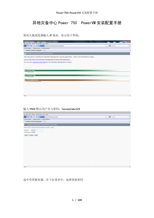
异地灾备中心Power 750 PowerVM安装配置手册使用火狐浏览器输入IP地址https://10.0.0.2,显示如下界面:
输入HMC默认用户名与密码:
hscroot/abc123
选中受管服务器,在下拉菜单中,选择更新密码
输入HMC默认密码 abc123
输入ASMI默认密码admin
选中受管服务器,下拉菜单>操作>开机
开机选项,选择“正常”
选择受管服务器,下拉菜单>属性
将“关闭所有逻辑分区后关闭系统”选项去掉
将受管服务器下的全分区关闭
选择立即关闭
选择“yes”
选择“no”
全分区已经关闭,如下图所示:
再次选择受管服务器,下拉菜单>属性
服务分区选择“未分配”
选中受管服务器的全分区,将全分区删除
选择“ok”
选中受管服务器,下拉菜单>配置>创建分区>AIX or Linux
分区名输入“test”
概要文件输入“test_profile”
选择专有处理器
按下图配置CPU
按下图配置存
将下列设备添加为“必须”(未完待续)
将下列设备添加为“必须”
添加后如下图所示:
添加后如下图所示:
一直单击下一步,直到出现如下画面,单击完成
创建后的分区如下图所示:
将系统诊断光盘放入光驱中,并激活test分区
选择打开终端窗口,并点击高级按钮
单击“ok”
浏览器弹出如下窗口,选择“始终信任此发行者的容”,单击是
输入“0”后回车
系统启动界面如下:
服务器需要扫描新硬件,时间比较长,请耐心等待(大约50分钟左右),如下图
输入“1”并回车
出现如下画面,并回车
如下画面,输入“3”并回车
输入“vt100”并回车
回车后出现如下画面:
使用键盘的“向下方向键”移动到如下画面,选择“Raid Array Manager”并回车
选择“IBM SAS Disk Array Manager”并回车
选择“List SAS Disk Array Configuration”并回车
选择“sissas0 Available 00-00 PCI Express x8 Ext Dual-x4 3Gb SAS Adapter”并回车
sissas0 与 sissas2 两块SAS卡位HA的关系,下面共有5块300GB SAS 硬盘,如下图所示:
按住ESC+3 返回,选择“sissas1 Available 01-00 PCI Express x8 Ext Dual-x4 3Gb SAS Adapter”并回车
Sissas1 与 sissas3 两块SAS卡位HA的关系,下面共有5块300GB SAS 硬盘如下图所示:
按ESC+3 返回,选择“Create an Array Candidate pdisk and Format to 528 Byte Sectors”回车
选择“sissas0 Available 00-00 PCI Express x8 Ext Dual-x4 3Gb SAS Adapter”并回车,如果出现如下画面
按ESC+3 返回,选择与sissas0 同一组的另外一块SAS卡sissas2,如下图所示:
按ESC+7 选择全部的5块硬盘回车,如下图所示:
出现确认窗口后回车:
回车后出现如下画面,此过程时间较长,请耐心等待格式化完成
5块硬盘全部格式化完毕后,如下图所示:
回车后如下图所示:
回车后,选择“sissas1 Available 01-00 PCI Express x8 Ext Dual-x4 3Gb SAS Adapter”
回车后如下图所示:
按ESC+7键选择所有5块硬盘,如下图所示:
出现确认对话框,回车
开始格式化磁盘,格式化时间比较长,请耐心等待,如下图所示:
格式化完成后如下图所示:
回车后如下图所示。