交通灯(proteus仿真设计+程序)
交通灯(proteus仿真设计+程序)

52单片机简易交通灯proteus仿真设计原理交通灯作为日常生活中必不可少的交通标志,它的设计是单片机初学者必不可少要接受的一项课题,下面简单介绍用proteus仿真一个由52单片机控制的简易交通灯。
本设计主要要求以下几个方面:一是根据系统控制要求设计硬件电路,这里是用PROTEUS软件来完成;二是根据硬件电路编写相应的程序流程图然后编写相关程序,这里程序的编制主要是用KeilC51软件来完成;三是在KEIL上用已经编好的程序生成.hex文件载入到PROTEUS中,实现PROTEUS与KEIL的联调,完成调试和仿真,观察调试结果是否满足设计要求,。
一:设计方案及重点:首先南北方向红灯、东西方向绿灯亮,南北方向红灯35秒、东西方向绿灯35秒,相应的数码管显示对应的数字并读秒,同时南北方向红色的交通灯和东西方向的绿色交通灯接通点亮显示,当东西方向的绿灯时间到,则东西方向的绿灯转为黄灯,同时数码管显示黄灯的时间3秒,东西方向的黄色二极管接通点亮,此时南北方向的红灯不变。
南北方向的红灯和东西方向的黄灯时间同时到,此时南北方向的红灯跳转为绿灯,时间同北方向的绿灯时间到,南北绿灯跳转为黄灯,东西方向的红灯不变,当南北方向的黄灯和东西方向的红灯时间到,南北方向的黄灯跳转为红灯,东西方向的红灯跳转为绿灯。
设计重点:1.数码显示管的计时2.数码管控制交通灯的转换3.锁存器与位选器端口的选择4.电路连接与程序编写二:仿真器件的介绍:1.单片机芯片:AT89C52, AT89C52是一个低电压,高性能CMOS 8位单片机, AT89C52单片机在电子行业中有着广泛的应用。
2.数码管:7SEG-MPX2-CC,这是一个两位数共阴极的数码管, 1就是左边数码管的阴极2就是右边数码管的阴极,a,b,c,d,e,f,g,就是数码管的段码,dp就是数码管的小数点3.锁存器与位选器:74HC573,具体作用:74HC573锁存器在数码管显示时作用的确是为了节省IO口,单片机P0口先发送abcdefghp段选信号,这时使用一个74HC573将段选信号保存住,单片机P0口再发送位选信号,此时单片机P0口信号不影响被锁存住的段选信号。
基于proteus的交通信号灯设计与仿真
宁波理工学院专业综合课程实习课程论文题目基于proteus的交通信号灯设计与仿真项目成员沈毅专业班级电气101指导教师裘君分院信息完成日期20013. 7.14目录一、题目及要求 ......................................1.1实验目的 ............................................1.2实验原理图 ..........................................二、软件设置 .............................................三、硬件原理图 ...........................................四、软件流程图 ...........................................五、设计结果(仿真+实物).................................5.1状态一...............................................5.2状态二...............................................5.2状态三...............................................5.2状态四...............................................六、个人心得 .............................................七、附件.................................................基于proteus的交通信号灯设计与仿真一、题目及要求实现一个如下基本功能的交通灯:按照常规我们假设一个十字路口为东西南北走向。
(完整word版)基于Proteus仿真交通灯
Proteus班级:电信13—2姓名:段学亮邓成智崔俊杰邓石磊陈亮高金玉成绩:电子与信息工程学院信息与通信工程系1.设计要求单片机的P3口的P3.0~P3。
7连接4×4矩阵键盘,P0口控制一只数码管,当4×4矩阵键盘中的某一按键按下时,数码管上显示对应的键号.例如,1号键按下时,数码管显示“1", 14号键按下时,数码管显示“E”等等.2.仿真电路图仿真电路图,如图一图1:4*4键盘控制数码管显示3。
仿真C51程序#include<reg52。
h>#define uchar unsigned char#define uint unsigned intsbit dula=P2^6;sbit wela=P2^7;uchar disnum,temp,key;void delay(uchar i){uchar j,k;for(j=0;j<i;j++)for(k=0;k〈200;k++);}uchar code table_du[]={0xc0,0xf9,0xa4,0xb0,0x99,0x92,0x82,0x7f8,0x80,0x90,0x88,0x83,0xc6,0xa1,0x86,0x8e,0xff};void main(){disnum=16;wela=0;while(1){P3=0xf0;temp=P3;temp=temp&0xf0;if(temp!=0xf0){delay(10);if(temp!=0xf0){temp=P3;temp=temp|0x0f;P3=temp;key=P3;switch(key){case 0xee :disnum=0;break;case 0xde :disnum=1;break;case 0xbe : disnum=2;break;case 0x7e :disnum=3;break;case 0xed :disnum=4;break;case 0xdd : disnum=5;break;case 0xbd : disnum=6;break;case 0x7d :disnum=7;break;case 0xeb : disnum=8;break;case 0xdb : disnum=9;break;case 0xbb : disnum=10;break;case 0x7b :disnum=11;break;case 0xe7 : disnum=12;break;case 0xd7 :disnum=13;break;case 0xb7 :disnum=14;break;case 0x77 :disnum=15;break;}}}P0=table_du[disnum];}}3.电路图仿真效果当按下键盘时,所显示的效果如图3—1至图3—4图3—1:当按下K0键时,数码管显示数字‘0’图3—2:当按下K4键时,数码管显示数字‘4'图3—3:当按下K8键时,数码管显示数字‘8’图3—4:当按下KF键时,数码管显示数字‘F' 5.总结电路设计方面,根据书本上还是课堂上老师所讲的知识,很快设计出来此仿真电路。
基于Proteus的数字交通灯电路设计与实现
基于Proteus的数字交通灯电路设计与实现要基于Proteus进行数字交通灯电路的设计与实现,可以按照以下步骤进行操作:
1. 打开Proteus软件,创建一个新的工程。
2. 在工程中选择一个适当的微控制器模型,例如Arduino UNO。
3.在工程中选择一个合适的LED灯模型,用于表示交通灯的红、黄、绿三种状态。
4.将LED灯模型拖放到电路图中,并与微控制器的相应引脚连接。
5.在电路图中添加一个电阻,用于限流保护LED灯。
6. 编写Arduino程序代码,实现交通灯的控制逻辑。
例如,可以使用if语句和延时函数来控制LED灯的亮灭。
7. 将编写好的Arduino程序代码上传到微控制器中。
8.保存并仿真运行电路图,观察交通灯的工作状态。
9.可以通过更改程序代码中的延时时间和控制逻辑,来模拟不同的交通灯工作模式,如红绿灯交替、黄灯闪烁等。
完成以上步骤后,即可实现基于Proteus的数字交通灯电路设计与实现。
交通灯proteus仿真设计

交通灯proteus仿真设计交通灯是城市交通管理中非常重要的一部分,它们用于控制车辆和行人的流动,确保交通的安全和顺畅。
在这篇文章中,我们将使用Proteus软件来设计一个交通灯的仿真模型。
在Proteus中,我们可以使用ISIS和Ares两个模块进行电子电路的设计和仿真。
首先,我们需要在ISIS中创建一个新的电路图。
我们可以将交通灯的每个部分视为一个独立的电路,包括信号发生器、计时器、红绿灯和行人信号等。
首先,我们需要一个信号发生器来模拟交通灯的计时控制。
我们可以使用Proteus中提供的脉冲发生器来生成一个方波信号作为计时器的输入。
我们可以设置方波的频率和占空比来模拟不同的交通灯状态,比如红灯、绿灯和黄灯。
接下来,我们需要一个计时器来控制交通灯的转换。
我们可以使用Proteus中提供的计时器元件,比如555定时器。
我们可以设置定时器的参数,比如时钟频率和周期,来控制交通灯的转换时间。
然后,我们需要设计红绿灯的电路。
对于红灯,我们可以使用一个LED来表示,可以选择红色的LED。
对于绿灯,我们也可以使用一个LED来表示,可以选择绿色的LED。
我们可以使用Proteus中提供的LED元件,并将其连接到计时器的输出引脚上。
最后,我们还可以添加一个行人信号来模拟行人通过的情况。
我们可以使用一个LED来表示行人信号,可以选择白色的LED。
我们可以将行人信号的LED连接到计时器的输出引脚上,并设置适当的延迟来控制行人信号的亮灭。
完成电路设计后,我们可以在ISIS中进行仿真。
在仿真过程中,我们可以观察交通灯的状态和行人信号的变化。
通过调整计时器的参数,我们可以模拟不同的交通灯时间间隔和行人信号的延迟时间。
除了电路设计和仿真,Proteus还可以进行PCB布局和打印板设计。
我们可以使用Ares模块来创建一个真实的交通灯电路板,并将其制作成实际的交通灯。
总而言之,通过Proteus软件的使用,我们可以方便地设计和仿真交通灯的电路,并进行交通灯的时间间隔和行人信号的延迟的调整。
基于Proteus模拟软件的交通灯系统设计说明书
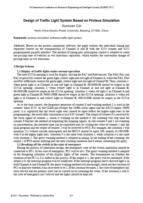
3rd International Conference on Mechanical Engineering and Intelligent Systems (ICMEIS 2015)Design of Traffic Light System Based on Proteus SimulationXuexuan CaiNorth China Electric Power University, Baoding, 071000, ChinaKeywords: proteus simulation software,traffic light systemAbstract. Based on the proteus simulation software, the paper realizes the individual timing and separated control on the transportation of Channel A and B with the 8254 counter and 8255 programmable parallel interface. The method of timing plus interruption control is adopted to count the passing time of vehicles in two directions separately, which enables the convenient change of passing times in two directions.1.Design Scheme1.1 Display of traffic lights under normal operationThe intel 8255A opening is used for display, leaving the PA7 and PA6 unused. The PA0, PA1 and PA2 respectively control the green light, yellow right and red light of Channel A, while the PA3, PA4 and PA5 differently control the green light, yellow right and red light of Channel B. Then, situation 1: when green light is in Channel A and red light in Channel B, 00100001B should be output in the 8255A opening; situation 2: when yellow light is in Channel A and red light in Channel B, 00100010B should be output in the 8255A opening; situation 3: when red light is in Channel A and green light in Channel B, 00001100B should be output in the 8255A opening; situation 4: when red light is in Channel A and yellow light in Channel B, 00010100B should be output in the 8255A opening.As to the time control, the frequency generator of counter 0 and working method 2 is used in the counter/ timer 8253. As the CLK0 pin receipts the 1MHz clock signal and the A8253 inputs 50000 (note: it is stipulated that the lower eight ones should be input before the higher eight ones in the programming), the result after calculation is just 0.05 seconds. The output of counter 0 is received by the clock signal of counter 1, which is working on the method 0: the counting will stop until the counter 0 finishes the method of outputting the jumping signals. As the counter 0 and 1 are counting in concatenation, the intended time can be controlled only by writing the value of counter 1 into the main program and the output of counter 1 will be received by PC0. For example, the situation 1 will maintain 25s without outside interruption and the B8253 should be input 500, namely 01100100B, with 0 in the higher eight ones. Situation 3 is the same with situation 1, while situation 4 is the same with situation 2. The query working method is adopted in timing. In the ending of the counting, the output 1 of PC0 means entering into the next working condition and 0 means continuing the query.1.2 Breaking off the switch in the state of emergencyDuring the process of simulation design, the emergency state of the switch simulation should be connected to PC1. In the state of emergency, PC1 will be low. The query working method is adopted in the foregoing situations of the display lights of the counter. The examination on whether the situation of the PC1 is 0 is added in the process. If the output is 1, the query will be continued; if the output is 0, the interrupt program will be conducted. If the interrupt program shows that red light is in both Channel A and Channel B, the query working method will unceasingly check out the situation of PC1 to find out whether it has recovered to be 1. If the situation becomes 1, the state of emergency has been relived and the primary state can be carried on by returning the scene; if the situation is still 0, the state of emergency isn’t relived and the lights should be kept red.2.Debug ResultsAfter the debug, the light display will be in cycle operation. If the green light of Channel A is interrupted, the red light of Channel A and B will be bright after the switch is pressed. The primary operation situation will be recovered when the switch is regained to Channel A and Channel B.The results of debug are as follows:Figure 1 Green light in Channel A and red light in Channel BFigure 2 Yellow light in Channel A and red light in Channel BFigure 3 Red light in Channel A and green light in Channel BFigure 4 Red light in Channel A and yellow light in Channel B Brief description on the debug results:(1)Figure 1 means Channel A is allowed to pass as there is green light but it is forbidden to pass Channel B as there is red light.(2)Figure 2 means that the 25s for green light in Channel A is up, the green light turns into yellow light reminding the coming of red light in the direction and red light is still in Channel B to forbid passing.(3)Figure 3 means that the 5s for yellow light in Channel A is up, it will turn into red light to forbid passing and there is green light in Channel B to allow passing.(4)Figure 5-4 means that the 25s for green light in Channel B is up, it turns into yellow light reminding the coming of red light in the direction and red light is still in Channel A to forbid passing.(5)The 5s is up and the system recovers to the primary state, namely, green light in south-north direction to allow passing and red light in Channel B to forbid passing, as shown in the following Figure. Based on the 60s cycle, the working functions of traffic lights are realized.(6) In case of emergencies, the button can be pressed to make red light on in both Channel A and Channel B, which is shown as follows:Figure 5 Red Light in both Channel A and Channel B3.SummaryThe paper conducts examination and simulation on the designed traffic system based on the proteus simulation software. By the simulation exercises, the functions of pins in 8086 chips can be understood more profoundly, such as how to use 8255 programmable parallel interface chips, how to take advantage of 8253 to make timing or output the pulses of certain frequency and how could the 8259 produce maskable interruption, etc. After the comparison between the simulation and the practical wirings and some slight adjustments on the program, the simulative traffic light system is easily built on the experiment box.References[1] Hong Yongquan. Microcomputer Principles and Interfacing Techniques [M]. Beijing: Science Press, 2009[2] Xu Zeming. Control Traffic Lights by Microcomputer [J]. Software Guide, 2007 (5)[3] Xiang Xinjian. Microcomputer Traffic Light Control System [J]. ASPT Source Journal, 1997 (09)。
基于Proteus的智能交通灯的仿真设计
基于Proteus的智能交通灯的仿真设计智能交通灯是一种基于现代科技的交通管理设备,通过智能化的控制系统和传感器,能够根据交通流量和道路情况,自动调整交通信号灯的时间和模式,以提高交通效率和安全性。
Proteus是一种功能强大的电子设计自动化(EDA)软件,它可以用于电路仿真和PCB设计。
在智能交通灯的仿真设计中,Proteus可以帮助我们建立交通信号灯的电路模型,并模拟不同情况下的交通流量和信号控制策略。
首先,我们需要设计交通信号灯的电路模型。
在Proteus中,我们可以使用元件库中的数字逻辑元件和LED元件来构建交通信号灯的电路。
通过连接适当的电源和控制信号,我们可以模拟交通信号灯的工作状态。
接下来,我们可以使用Proteus的仿真功能来模拟不同情况下的交通流量和信号控制策略。
通过设置不同的输入信号和参数,我们可以观察交通信号灯在不同条件下的工作效果。
比如,我们可以模拟高峰时段和低峰时段的交通流量,观察交通信号灯的调整情况以及车辆通过的效率。
在仿真设计中,我们还可以使用Proteus的调试功能来分析交通信号灯的电路和控制逻辑。
通过设置断点和监视变量,我们可以观察电路中各个信号的变化情况,以及控制逻辑的执行过程。
这有助于我们发现潜在的问题并进行调整和改进。
除了仿真设计,Proteus还可以用于PCB设计和实际制造。
通过将电路设计转化为PCB布局,我们可以将交通信号灯的电路制作成实际的电子板,并安装在实际的交通信号灯中进行测试和调试。
总之,基于Proteus的智能交通灯的仿真设计可以帮助我们模拟不同情况下的交通流量和信号控制策略,并分析交通信号灯的电路和控制逻辑。
这有助于我们优化交通信号灯的设计,提高交通效率和安全性。
同时,Proteus还可以用于PCB设计和实际制造,使我们的设计能够实际应用于交通管理中。
基于Proteus的智能交通灯设计与仿真实现
基于Proteus的智能交通灯设计与仿真实现智能交通灯是一种通过传感器和智能控制系统实现交通信号灯的智能化管理,能够根据交通流量和道路状况进行智能调控,以提高交通效率和减少交通堵塞。
本文将基于Proteus软件进行智能交通灯的设计和仿真实现。
首先,我们需要明确智能交通灯的基本功能和设计要求。
智能交通灯主要需要实现以下功能:1.根据交通流量进行智能控制。
通过传感器检测道路上的交通流量,智能交通灯可以根据实时的交通情况智能地调整信号灯的时间,以提高交通效率。
2.考虑不同道路的优先级。
在交叉路口附近,智能交通灯需要根据不同道路的优先级来调整信号灯的时间,以确保交通的顺畅和安全。
3.考虑行人的过马路需求。
智能交通灯需要合理地安排行人的过马路时间,以保证行人的安全和顺畅。
接下来,我们将使用Proteus软件进行智能交通灯的设计和仿真实现。
Proteus是一款电子电路设计和仿真软件,可以用来模拟和验证电子电路的性能和功能。
首先,我们需要设计智能交通灯的硬件电路。
在Proteus中,我们可以使用元器件库中的LED灯和开关等元件来构建交通灯的电路。
同时,我们还需要添加传感器来检测交通流量和行人的需求。
在设计电路的过程中,我们需要考虑不同道路的优先级和行人的过马路需求。
根据道路的优先级,我们可以设置不同道路对应的信号灯的亮灭时间。
同时,我们还可以设置传感器来检测行人的需求,以在需要的时候提供行人过马路的时间。
完成电路设计后,我们可以使用Proteus中的仿真功能来验证电路的性能和功能。
在仿真过程中,可以模拟不同道路的交通流量和行人的过马路需求,以观察交通灯是否能够根据实时情况进行智能调控。
在仿真过程中,我们可以观察交通灯的状态变化和信号灯的亮灭时间,以评估交通灯的性能和效果。
如果发现问题,我们可以对电路进行调整和优化,以提升交通灯的智能化管理能力。
总结起来,基于Proteus的智能交通灯设计和仿真实现是一种高效且可靠的方法。
十字路口交通灯Proteus仿真
《微机原理与接口技术》课程设计报告题目:十字路口交通灯设计学院:信息工程学院专业:通信工程目录1、摘要 (1)2、硬件电路图 (2)3、AT89C51功能介绍 (3)4、交通灯程序设计思路 (5)5、交通灯运行流程图 (6)6、源代码函数说明 (6)7、交通灯设置红绿灯时间结果图 (8)8、心得与体会 (9)9、源程序代码 (10)摘要十字道口的红绿灯是交通法规的无声命令,是司机和行人的行为准则。
十字道口的交通红绿灯控制是保证交通安全和道路畅通的关键。
当前,国内大多数城市正在采用“自动”红绿交通灯,它具有固定的“红灯—绿灯”转换间隔,并自动切换。
它们一般由“通行与禁止时间控制显示、红黄绿三色信号灯和方向指示灯”三部分组成。
通常,生活中常见的红绿灯控制为,红灯六十秒,绿灯四十五秒,黄灯三秒等,因道路,车辆,城市交通规划而异,此次,基于proteus仿真十字路口的交通灯控制系统,设定南北方向绿灯15秒,黄灯5s,东西方向绿灯10s,黄灯5s。
系统基于MSC-51系列单片机89C51为中心器件来设计交通灯,显示器件为LED 红绿灯,LCD数码管。
采用c51编程,简单易懂,将功能模块化,除了可以实现红绿灯按要求变化,还通过proteus里的按钮,设置了键盘函数,可以按要求调整红绿灯亮的时间,并且还有重置(初始化)按钮。
一.功能概述1.设计任务:交通灯的硬件设计和软件设计2.设计目的:(1).初步了解和认识51单片机的工作原理,引脚图。
(2).掌握单片机相关接口技术和相关外围芯片的特性。
( 3 ).通过实际的设计程序,查找资料,调试程序,熟悉keil和proteus软件仿真,理解并熟悉模块化程序设计方法和调试。
3.基本要求:利用单片机的定时器产生秒信号,控制十字路口的红、绿、黄灯交替点亮和熄灭,并且用 4 只LED 数码管显示十字路口两个方向的剩余时间。
当东西方向亮绿灯时,南北方向红灯亮起;反之,如果南北方向亮绿灯,同时东西方向亮绿灯;绿灯亮时车辆行驶,红灯亮时车辆停止。
交通灯(proteus版本)
一般十字路口的交通灯控制系统的工作状态及其功能如表1:
表1
控制器状态
信号灯状态
车道运行状态
S0(00)
S1(01)
S3(11)
S2(10)
甲绿,乙红
甲黄,乙红
甲红,乙绿
甲红,乙黄
甲车道通行,乙车道禁止通行
甲车道缓行,乙车道禁止通行
甲车道禁止通行,乙车道通行
2、焊电路板过程中的问题
(1)芯片的布局
首先要考虑元器件布局的问题,很多同学仅仅只考虑了芯片摆放的美观性却忽略了合理地摆放芯片的重要性。合理的摆放芯片其实比美观地摆放芯片更重要,因为合理的布局能够大大减少电路板上飞线的长度。比如,译码器74LS74就最好摆在计数器74ls161的正上方,因为74LS74的1、2、6、7引脚就是和74161的11、12、13、14引脚相连,所以这些引脚靠的越近越好。
0 0 1
0 0 1
0 0 1
0 0 1
1 0 0
0 1 0
三、单元电路的设计:
1、基于NE555的秒方波发生器
用NE555芯片以及外围电路搭建成一个多谐振荡器,通过设计外围电路的参数输出方波频率为1Hz,故称为秒方波发生器。由于脉冲的占空比对系统的影响不大,故把占空比设计为1/3。输出方波用作计数器及D触发器的clk信号。NE555定时器引脚图如图1所示,脉冲频率公式:
74LS153
2
3
四输入与门
74LS04
2
4
六输入非门
74LS00
2
5
双D触发器
74LS74
1
6
发光二译码
7448
2
- 1、下载文档前请自行甄别文档内容的完整性,平台不提供额外的编辑、内容补充、找答案等附加服务。
- 2、"仅部分预览"的文档,不可在线预览部分如存在完整性等问题,可反馈申请退款(可完整预览的文档不适用该条件!)。
- 3、如文档侵犯您的权益,请联系客服反馈,我们会尽快为您处理(人工客服工作时间:9:00-18:30)。
52单片机简易交通灯proteus仿真设计原理
交通灯作为日常生活中必不可少的交通标志,它的设计是单
片机初学者必不可少要接受的一项课题,下面简单介绍用proteus
仿真一个由52单片机控制的简易交通灯。
本设计主要要求以下几个方面:一是根据系统控制要求设计
硬件电路,这里是用PROTEUS软件来完成;二是根据硬件电路编写
相应的程序流程图然后编写相关程序,这里程序的编制主要是用KeilC51软件来完成;三是在KEIL上用已经编好的程序生成.hex
文件载入到PROTEUS中,实现PROTEUS与KEIL的联调,完成调试
和仿真,观察调试结果是否满足设计要求,。
一:设计方案及重点:
首先南北方向红灯、东西方向绿灯亮,南北方向红灯35秒、东西方向绿灯35秒,相应的数码管显示对应的数字并读秒,同时南北方向红色的交通灯和东西方向的绿色交通灯接通点亮显示,当东西方向的绿灯时间到,则东西方向的绿灯转为黄灯,同时数码管显示黄灯的时间3秒,东西方向的黄色二极管接通点亮,此时南北方向的红灯不变。
南北方向的红灯和东西方向的黄灯时间同时到,此时南北方向的红灯跳转为绿灯,时间同北方向的绿灯时间到,南北绿灯跳转为黄灯,东西方向的红灯不变,当南北方向的黄灯和东西方向的红灯时间到,南北方向的黄灯跳转为红灯,东西方向的红灯跳转为绿灯。
设计重点:
1.数码显示管的计时
2.数码管控制交通灯的转换
3.锁存器与位选器端口的选择
4.电路连接与程序编写
二:仿真器件的介绍:
1.单片机芯片:AT89C52, AT89C52是一个低电压,高性能CMOS 8位单片机, AT89C52单片机在电子行业中有着广泛的应用。
2.数码管:7SEG-MPX2-CC,这是一个两位数共阴极的数码管, 1就是左边数码管的阴极2就是右边数码管的阴极,a,b,c,d,e,f,g,就是数码管的段码,dp就是数码管的小数点
3.锁存器与位选器:74HC573,具体作用:74HC573锁存器在数码管显示时作用的确是为了节省IO口,单片机P0口先发送abcdefghp段选信号,这时使用一个74HC573将段选信号保存住,单片机P0口再发送位选信号,此时单片机P0口信号不影响被锁存住的段选信号。
,使用另一个74HC573锁存住位选信号。
按以上循环,显示8位数码管只需要10个IO口。
4.上拉电阻:RESPACK-8,作用,拉高端口电压,稳定端口电压值。
5.交通灯:TRAFFIC LIGHTS。
三.设计原理概述:
1.设计采用52单片机系统,AT89C52片内含8k bytes的可反复擦写的Flash只读程序存储器和256 bytes的随机存取数据存储器(RAM),器件采用ATMEL公司的高密度、非易失性存储技术生产,兼容标准MCS-51指令系统,片内置通用8位中央处理器和Flash存储单元相较于51芯片而言,52芯片储存能力较强大,易于读取,性能明显优于51芯片。
2.本设计采用二位八段数码管,并用U2做位选,选择数码管亮的位置,连接p2口,U3做段选,选择数码管如何亮。
位选器U2与段选器U3控制数码管的显示,辅以程序来控制数码管的倒计时显示。
3.交通灯用共阳式接法,接至单片机P1.2-P1.4端口。
低点位输出时,交通灯被点亮,高电位输出时,交通灯被熄灭。
同时用程序语言来达到数码管控制交通灯的点亮与熄灭。
上拉电阻般作单键触发使用时,如果电路本身没有内接电阻,为了使单键维持在不被触发的状态或是触发后回到原状态,必须在电路外部另接一电阻。
此处采用上拉电阻的作用就是为了使电路更加稳定。
程序:
#include<reg52.h>
#define uchar unsigned char
#define uint unsigned int
sbit dula=P2^6;
sbit wela=P2^7;
uchar code table[]={ //对数码管显示的数字进行编号
0x3f,0x06,0x5b,0x4f,
0x66,0x6d,0x7d,0x07,
0x7f,0x6f,0x77,0x7c,
0x39,0x5e,0x79,0x71
};
uchar num=35,num1=1,num2,num3,num4=35,num5=3,shi,ge;
void delay(uint);
void display(uchar,uchar);
main()
{
TMOD=0x11; //设置定时器0为工作方式1
TH0=(65536-45872)/256;
TL0=(65536-45872)%256;
TH1=(65536-45872)/256;
TL1=(65536-45872)%256;
EA=1; //开总中断
ET0=1; //开定时器0中断
ET1=1;
TR0=1; //启动定时器0
TR1=1;
P1=0x04;
while(1) //程序在此扫描等待间断发生
{
display(shi,ge); //执行数码管段位选函数}
}
void display(uchar shi,uchar ge)
{
P0=table[shi]; //将十位作为段选数据输送
dula=1;
dula=0;
P0=0xfe; //送位选数据
wela=1;
wela=0;
delay(5);
P0=0xff;wela=1;wela=0; //进行消影操作
P0=table[ge]; //将个位作为段选数据输送
dula=1;
dula=0;
P0=0xfd; //送位选数据
wela=1;
wela=0;
delay(5);
P0=0xff;wela=1;wela=0; //进行消影操作}
void delay(uint x) //延时函数
{
uint i,j;
for(i=x;i>0;i--)
for(j=110;j>0;j--);
}
void T0_time() interrupt 1 //数码管间断
{
TH0=(65536-45872)/256;
TL0=(65536-45872)%256;
num2++;
if(num2==20) //循环20次位为一秒,在将num2置零后重记下一秒
{
num2=0;
num--;
if(num==0)
{num=35;num1++;if(num1%2==0) num=3;}
//如果num1被2整除,则轮到黄灯亮,num置成3
shi=num/10; //程序将十位个位传回
ge=num%10;
}
}
void T1_time() interrupt 3 //交通灯间断
{
TH1=(65536-45872)/256;
TL1=(65536-45872)%256;
num3++;
if(num3==20) //循环20次位为一秒,在将num3置零后重记下一秒
{
num3=0;
num4--;
if(num4==0)
{num4=35;num5++;
if(num5%2==0) {num4=3;P1=0x08;} //达到条件,黄灯亮
if((num5+1)%4==0) P1=0x04; //达到条件,红灯亮
if((num5-1)%4==0) P1=0x10; //达到条件,绿灯亮
}
}
}
仿真:
图一。