米亚基大电流监测仪MM-315B说明书
MiCOM P12y使用说明书

在可翻开的下盖板的下面,有一个电池舱,可使用½AA 型电池。该电池可作
为后备电源,保存保护装置存储器中的事件记录,故障记录和故障录波(仅对
P126 和 P127)。盖板下还有一个 9 针的母 D 型前部通讯端口。它的作用是通过
RS232 串行数据连接(SK1 口),在本地实现 PC 机和保护装置的通讯(最长距离
且跳闸原因也被复位后,指示灯熄
灭。
警告指示灯(L3:桔黄色 LED 指示灯,标注为 Warning):
灯亮表示 MiCOM P12y 保护装置有内部警告。当检测到一个“非严重”的内部 警告时,该指示灯将持续闪烁。只有当导致内部警告的原因不存在了(修理模块,故 障消失等),指示灯才会熄灭。
辅助电源(L4:绿色 LED 指示灯,标注为 Aux. Supply):
灯亮表示 MiCOM P12y 保护装置工作正常,装置电源的辅助电源存在。
可自由编程的指示灯(L5 to L8:标签自由标注):
这些 LED 指示灯可以由用户以提供的门槛(瞬动和延时信号)信息为基础自由 编程。用户选择他想用指示灯看到的信号,通过菜单将它们分配到每一个 LED 指示 灯上(用逻辑 OR)。当相关信号启动时,对应的指示灯亮。当相应的报警被确认了 之后,指示灯熄灭。
第 3 页/共 24 页 使用说明书
21 21 21 21 21 22 22 23 23 23 24 24 24
上海阿海珐电力自动化有限公司 MiCOMP12y 系列
第 4 页/共 24 页 使用说明书
1. 装置介绍
MiCOM P125、P126、P127 系列保护装置是法国 AREVA 公司继 K 系列、 MODN 系列以及 MX3 系列产品获得成功后新研制的换代产品。所设计的 MiCOM P125、 P126、P127 保护装置具有保护、控制和监视等多重功能,适用于工业, 配电网络和变电站中,可作为变压器和发电机变压器保护方案的一部分以及为高压 和超高压输电系统提供后备保护等。
DEM锁具电量测试仪-用户手册

二:解决锁具工作电流动态范围大的测试难点 针对电子锁具,其电流测量难点在于电流动态范围极大,峰值可能达到近 500mA,
mA(该值仅供参考)。 普通状态: 功耗(mAh):显示“— — — — — —”; 平均值(AVG): 每 0.5S 刷新显示一次,显示这 0.5S 内的电流平均值,单位
为 mA;
峰值(MAX):每 0.5S 刷新显示一次,显示这 0.5S 内的电流最大值,单位为
mA(该值仅供参考)。
13. 停止/退出键
注意:
本说明书内容有可能变动,恕不另外通知,但可保证本说明书与所购仪器一致。 我们已经尽最大努力准备本说明书,以确保其准确性。然而,如您有疑问或发现错误,请 直接与本公司或本公司授权代理商联系。 没有本公司书面许可,任何抄袭或改编本手册全部或部分内容均为严重侵权。 用户第一次打开仪器包装箱时,请对照装箱清单,检查仪器和配件,若发现配件不齐或仪 器配件不正常,请立即与本公司或销售商联系。
当遇到电源保险丝烧毁的情况当遇到电源保险丝烧毁的情况当遇到电源保险丝烧毁的情况当遇到电源保险丝烧毁的情况后更换同规格保险丝仍出现烧毁保险丝的情况后更换同规格保险丝仍出现烧毁保险丝的情况后更换同规格保险丝仍出现烧毁保险丝的情况后更换同规格保险丝仍出现烧毁保险丝的情况后请及时将仪器送修请及时将仪器送修请及时将仪器送修请及时将仪器送修不要随意更换更大容量保险丝而强制让仪器带病工作不要随意更换更大容量保险丝而强制让仪器带病工作不要随意更换更大容量保险丝而强制让仪器带病工作不要随意更换更大容量保险丝而强制让仪器带病工作以免造成人员或财物损失以免造成人员或财物损失以免造成人员或财物损失以免造成人员或财物损失
米亚基使用说明书

·焊接机构采用风冷和水冷装置,使焊接温度控制在设定范围内,保证了工件的安全,并延长了焊头的使用寿命。
二、技术参数
1、使用电源:AC380V±5% 50HZ 45A
(一)换向器直径:20~120(mm)
3、换向器长度:≤50mm
图3
⑵在图3界面进行参数设置,如设置转位电机速度,手点击触摸屏中转位速度后的方框,在随后跳出的数字选择对话框中选择您所要的数据,按ENTER键这样您所要的数据就将自动储存到系统中。对其他参数的设置方法也是如此。
(应注意的是,在我们改变点焊转子类型时,应及时更改转子槽数该参数,如当前所点焊转子换向器为24槽,接着我们要点焊的转子换向器为40槽等其它数值时,须把将要点焊转子的正确槽数设置进入系统中,再实施点焊。)
米亚基使用说明书
一、功能及特点
BSD-DH换向器自动电焊机是集机械、电脑及电气为一体、专为串激式电机卡线型换向器和钩型换向器点焊作业而设计的专用设备。
特点如下:
·采用混合式步进电机及驱动器,具有噪音低、调速方便、无线变速及频率高适用范围大,焊接准确之特点。
·采用合理的机械式点焊;自动夹紧工件、自动焊接、自动转位,焊接完成自动停止等等。
③要使米亚基焊接控制进入工作(焊接)状态,还需将米亚基面板右下角的焊接开关键WELD打开,使接通指示灯亮起。
④位于面板最下方的中间二个按键COUNT和SQUEEZE不要打开,通常情况下都在“关闭”状态。
2、参数设定
①当完成以上四点后,通常情况下,面板各显示部位全部亮起,最上端亮起的数字显示部(如图)是焊接规范
2、电源的连接机床接电前检查电源电压是否与本机床规定的电源相符(即AC380±5%),本机使用三相四线为输入电源线。请勿误接。接电前请务必接好地线,且接地点阴应小于4Ω
大电流监测仪MM-315B使用说明

-`焊接测试机MM-315B使用说明书感谢您购买MIYACHI 公司的焊接测试机MM-315B。
为正确使用本产品,请从头至尾仔细阅读本“使用说明书”。
另外,请在阅读后就近保存本说明书,以便随时翻阅。
米亚基(集团)公司目录1. 特别注意事项 (1)(1)安全注意事项 (1)(2)使用注意事项 (4)2. 前言 (1)(1)主体及附属品 (1)(2)非附随品 (1)3. 焊接测试机的各部件名称 (1)4. 关于检测 (1)(1)环形线圈的设置 (1)(2)接通电源 (2)(3)确认检测条件 (3)(4)检测条件的设置 (4)a. 范围的设置 (4)b. 脉冲NO.的设置 (5)c. NOTE1.脉冲NO.设置及显示 (6)d. 开始周期的设置 (8)e. 最终周期的设置 (9)(5)通电角的确认 (10)(6)变频器焊接机的检测 (11)(7)关于全脉冲储存 (13)(8)关于半周期单位的显示 (16)(9)关于强制检测周期 (16)(10)关于超值显示 (16)5. 按钮及其功能 (1)6. 规格 (1)7. 外观图 (1)8. 关于充电方法 (1)(1)连接主机和充电器 (1)(2)关于充电时期 (1)(3)关于充电中的检测操作 (1)(4)关于镍氢电池的寿命 (2)(5)镍氢电池的更换方法 (2)9. 校正 (1)11. 特别注意事项(1) 安全注意事项请在使用前仔细阅读此“安全注意事项”,以便正确使用本产品。
■ 为安全使用本产品,并将其对使用者或其他人可能造成的危害或损害防范 于未然,从而编写了该安全注意事项。
■ 此处所列每条内容皆涉及安全事项,因此请仔细阅读。
■ 每个符号所代表的内容如下所示危险 错误使用将危及生命或导致重伤。
警告 错误使用将可能危及生命或导致重伤。
注意 错误使用将可能使人受伤或损坏物品。
表示“禁止”。
警告所示行为不在产品保证范围内。
产品使用者必须遵守的行为。
△符号表示所示行为可能导致危险·警告·注意事项。
AB表 用户手册

一即心至中XK315A/B型智能重量显示控制器用户手册提示:本手册是XK315A/B系列智能重量显示控制器(重量变送器)仪表的详尽使用说明。
仪表所具有的功能是依据定货合同,如有不同处请做以参考;考调试人员和用户单位的计量管理人员应通读全文,一般操作人员在上岗前经简单培训并按照另行提供的《速查手册》所列步骤操作即可。
一、概述XK315B/A型智能重量显示控制器(重量变送器,以下简称仪表)是我公司自行研制开发的新一代双路称重显示控制型仪表。
它可对两路重量信号进行独立\相加显示、变送、超载报警、限制控制、钢缆重量补偿、数传无线传输(远程显示、变送、控制)等;适用在行车称重(大小吊钩或双钩称重叠加显示),轧制力称重,钢管称重等需用双路称重显示控制的场地。
且现场环境恶劣,电源波动严重和无人操作场合使用;可满足大多数用户使用,另可根据用户要求定制增加特殊功能。
本仪表广泛应用于码头、仓库、冶金、矿山、物流等企业;二、工作原理该仪表CPU以W89E56为系统核心。
标定、设定等工作参数采用EEPROM断电可保存。
两路传感器输出的重量信号经双路完全相互独立的高集成IC进行数据放大器、低通有源滤波器处理后,送∑-△型AD转换器转换成数字量,(另可换配数字接线盒接口,选配钢缆输入接口,)主机将该信号读入处理器后,分成多路进行输出和控制。
工作原理框图系统工作原理框图三、主要功能与技术指标(一)主要功能:★具有全面板参数设置功能;★采用全数字称重标定技术,可对称量值进行自动或手动标定;★采用带硬件保护的EEPROM存储器,具有掉电数据保护功能;★具有称量动态检测、数据稳定化处理的功能;★具有两路控制设定开关量输出(可加配到四路);★具有外接大屏幕输出接口;(信号方式,RS232C,485,电流环,TTL等);★可选配钢丝绳重量补偿功能,可使重量值在整个起吊行程保待稳定不变;★可选配串行数据通讯接口,便于同工业控制计算机、PLC联网;★可选配用数字接线盒,可使称重系统工作在恶劣的环境中;★可选配用数传电台,组成无线称重系统;★可选配标准模拟量信号功能,可选配一到两路,便于现场灵活应用;★采用独特的输出保护电路,具有良好的抗干扰性,可在恶劣的环境中使用;★具有故障自检功能,便于仪表检测维修。
电磁测量仪产品说明书

ElettrologiaCampo magneticoCampo geomagneticoDETERMINAZIONE DELLE COMPONENTI ORIZZONTALE E VERTICALE DEL CAMPO GEOMAGNETICO.UE3030700 04/16 MEC/UDFig. 1: Disposizione per la misurazione.BASI GENERALILa terra è circondata da un campo geomagnetico, prodot-to dalla cosiddetta geodinamo. In prossimità della super-ficie terrestre il campo è simile al campo magnetico gene-rato da un dipolo, le cui linee di campo partono dall’emisfero terrestre meridionale per poi rientrare nel’emisfero settentrionale. L’angolo tra la direzione del campo geomagnetico e il piano orizzontale viene detto inclinazione. La componente orizzontale del campo geo-magnetico corre essenzialmente parallelamente alla dire-zione nord-sud. Poiché la crosta terrestre è magnetizzata in modo diverso, si verificano scostamenti a livello loca-le; questo fenomeno è denominato declinazione.Fig. 2: Rappresentazione delle componenti dei campi magne-tici esaminati nell’esperimento e definizione del rel ativo angolo.Nell’esperimento vengono esaminati l’inclinazione e l’intensità, nonché la componente orizzontale e verticale del campo geomagnetico nel punto di misurazione. Si applica la correlazione (Fig. 2):(1) v h tan B B =⋅αα: InclinazioneB h : Componente orizzontale B v : Componente verticale e(2) B È pertanto sufficiente determinare le grandezze B h e α, per poter determinare anche le altre due.L’inclinazione α viene rilevata utilizzando un inclinatorio. Per determinare la componente orizzontale B h lo stesso inclinato-rio sull’orizzontale viene orientato in modo tale che l’ago di bussola integrato, che tende a disporsi parallelamente alla componente orizzontale, sia puntato sullo 0. Una coppia di bobine di Helmholtz genera un campo magnetico orizzontale supplementare B HH perpendicolare a B h determinando la rotazione dell’ago di un angolo β. Come da Fig. 2, vale(3)HHhtan B B =β Ai fini del miglioramento dell’accuratezza del dato, questa misurazione viene eseguita per diversi angoli β.ELENCO DEGLI STRUMENTI1 Bobine di Helmholtz da 300 mm 1000906 (U8481500) 1 Alimentatore CC 0-20 V, 0-5 A @230V 1003312 (U33020-230) o 1 Alimentatore CC0-20 V, 0-5 A @115V1003311 (U33020-115) 1 Multimetro digitale P1035 1002781 (U11806) 1 Inclinatorio E1006799 (U8495258) 1 Reostato a corsoio 100 Ω 1003066 (U17354) 1 Set di 15 cavi di sicurezza per esperimenti, 75 cm1002843 (U138021)MONTAGGIO E ESECUZIONENota:Preparare l'esperimento su una superficie orizzontale e piana posta in un luogo in cui la misurazione non sia soggetta a interferenze magnetiche ambientali.Determinazione della componente orizzontale B h ∙Per mezzo del volantino ruotare l'inclinatorio in modo tale che il piano del cerchio graduato e dell'ago della bussola sia parallelo alla superficie di appoggio.In questo modo l'ago della bussola si orienta sempre lungo la componente orizzontale del campo geomagnetico. ∙Ruotare l'inclinatorio sulla piastra di base in modo tale che le tacche 0° del cerchio graduato corrispondano alla direzione dell'ago della bussola.∙Spingere le bobine di Helmholtz sopra l'inclinatorio, fin-ché quest'ultimo non si trovi al centro fra le bobine (fig. 1) e l'asse delle bobine di Helmholtz non sia perpendicolare alla direzione dell'ago della bussola.∙ Collegare in serie le bobine di Helmholtz, il multimetro digita-le e il potenziometro scorrevole all'alimentatore (fig. 1). ∙ Regolare il potenziometro scorrevole su 100 Ω.∙Accendere l'alimentatore e aumentare la corrente, alzan-do la tensione tramite il regolatore fine di tensione conti-nua, finché la direzione dell'ago della bussola non corri-sponda alle tacche 5° del cerchio graduato. Annotare l'angolo di deviazione β = 5° nella tab. 1. Leggere sul multimetro il valore di corrente I e annotarlo nella tab. 1. ∙Aumentare progressivamente la corrente, in modo tale che l'angolo di deviazione si ingrandisca di 5° alla volta fino a raggiungere β = 75°. Annotare rispettivamente l'angolo di deviazione e il valore di corrente nella tab. 1. Quando il regolatore fine di tensione continua raggiunge la battuta, aumentare la corrente riducendo la resistenza mediante il potenziometro scorrevole.Determinazione dell’i nclinazione α ∙Per mezzo del volantino ruotare l'inclinatorio in modo tale che il piano del cerchio graduato e dell'ago della bussola sia parallelo alla superficie di appoggio.In questo modo l'ago della bussola si orienta sempre lungo la componente orizzontale del campo geomagnetico. ∙Ruotare l'inclinatorio sulla piastra di base in modo tale che le tacche 0° del cerchio graduato corrispondano alla direzione dell'ago della bussola.∙Mediante il volantino ruotare l'inclinatorio in modo tale che il piano del cerchio graduato e dell'ago della bussola sia perpendicolare alla superficie di appoggio. ∙ Attendere che l'ago della bussola si fermi.∙ Leggere l'angolo dell'inclinatorio α1 sul cerchio graduato dell'inclinatorio e annotarlo nella tab. 2.∙ Mediante il volantino ruotare l'inclinatorio di 180°. ∙ Attendere che l'ago della bussola si fermi.∙ Leggere l'angolo dell'inclinatorio α2 sul cerchio graduato dell'inclinatorio e annotarlo nella tab. 2.3B Scientific GmbH, Rudorffweg 8, 21031 Amburgo, Germania, ESEMPIO DI MISURAZIONE E ANALISITab. 1:I impostate e campimagnetici B HH delle bobine di Helmholtz calcolati in base all'equazione (5).Tab. 2: Inclinazione α determinata dalla media di entrambi ivalori misurati α1 e α2Determinazione della componente orizzontale B h Da (3) consegue che:(4) HH h tan B B =⋅βLa componente orizzontale B h corrisponde alla pendenza di una retta passante per l’origine ch e passa per i punti di misu-ra in un diagramma B HH – tan α.Il campo magnetico B HH della coppia di bobine di Helmholtz può essere determinato in modo semplice. All’interno di una coppia di bobine esso è fortemente omogeneo e proporziona-le all’intensità di co rrente I che attraversa una singola bobina:(5) HH B k I =⋅ con3274Vs 4105Am N k R -⎛⎫=⋅π⋅⋅ ⎪⎝⎭N = 124: Numero di spire R = 147,5 mm: Raggio ∙Calcolare il campo magnetico B HH della coppia di bobine di Helmholtz per tutte le correnti impostate I (tab. 1) in base alla formula (5) e annotare i risultati nella tab. 1.12345050100tan βB HH / T μFig. 3: Diagramma B HH – tan α per la determinazione dellacomponente orizzontale del campo geomagnetico∙ Riportare in un diagramma il campo magnetico B HH infunzione di tan β e unire i punti con una linea retta (fig. 2). ∙Determinare la componente orizzontale B h direttamente dall'incremento lineare. (6) h 23T B =μDeterminazione della componente verticale B dall'inclina-zione α ∙Determinare l'inclinazione α, facendo la media di entram-bi i valori misurati α1 e α2 (tab. 2) e annotare il valore ri-cavato nella tab. 2.∙Determinare la componente verticale in base alla formula (1).(7) v h tan 23T tan60,541T B B =⋅α=μ⋅︒=μDeterminazione del valore complessivo ∙Determinare il valore complessivo del campo magnetico B in base alla formula (2). (8) 47T B =μI valori ottenuti dalla misurazione della componente orizzonta-le e di quella verticale corrispondono in gran parte con i valori riportati in letteratura, riferiti all'Europa centrale B h = 20 μT e B = 44 μT.。
(仅供参考)米亚基控制器(CT-110C中文版)
外部输入输出信号 ················································································································ 2
时序图···································································································································· 操作方法 --------------------------------------------------------------------------------------------------------
最大电流的设定 ···················································································································· 6
电流校正的方法 ···················································································································· 电池和保险丝的更换 -----------------------------------------------------------------------------------------
● 打开捆包箱后,请确认本装置是否在运输过程中受到破损、附属品是否配备齐全。 万一发现装置受损或附属品不全,请立即与销售商或营业担当联系。
3B S CIENTIFIC 演示多功能多尺度电压电流计说明书
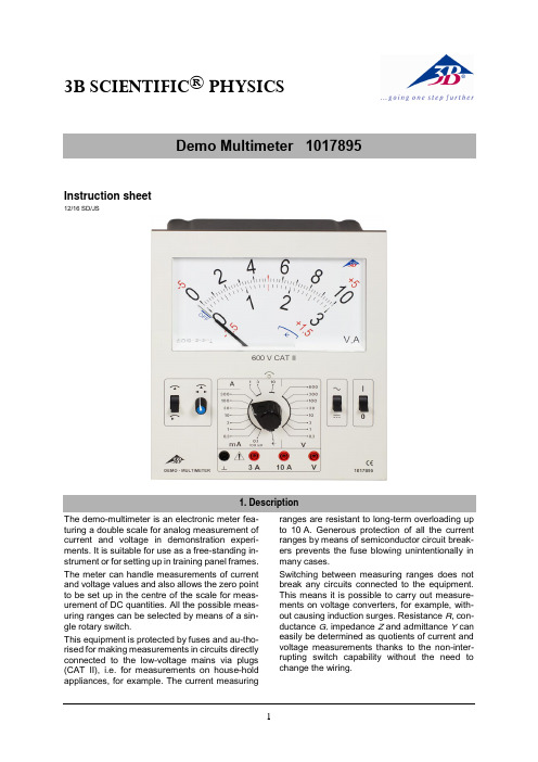
3B SCIENTIFIC ® PHYSICSInstruction sheet12/16 SD/JSThe demo-multimeter is an electronic meter fea-turing a double scale for analog measurement of current and voltage in demonstration experi-ments. It is suitable for use as a free-standing in-strument or for setting up in training panel frames. The meter can handle measurements of current and voltage values and also allows the zero point to be set up in the centre of the scale for meas-urement of DC quantities. All the possible meas-uring ranges can be selected by means of a sin-gle rotary switch.This equipment is protected by fuses and au-tho-rised for making measurements in circuits directly connected to the low-voltage mains via plugs (CAT II), i.e. for measurements on house-hold appliances, for example. The current measuringranges are resistant to long-term overloading up to 10 A. Generous protection of all the current ranges by means of semiconductor circuit break-ers prevents the fuse blowing unintentionally in many cases.Switching between measuring ranges does not break any circuits connected to the equipment. This means it is possible to carry out measure-ments on voltage converters, for example, with-out causing induction surges. Resistance R , con-ductance G, impedance Z and admittance Ycan easily be determined as quotients of current and voltage measurements thanks to the non-inter-rupting switch capability without the need to change the wiring.The demo multimeter conforms to safety regula-tions for electrical measurement, control and la-boratory equipment, as specified in DIN EN 61010-1, protection class 2 and to measuring ca-tegory CAT II for up to 600 V. The nominal volt-age between the phase conductors and the neu-tral for voltage and current measurements (in cir-cuits directly connected to mains electricity) must not exceed 600 V in order to conform to CAT II. The meter is intended for measurements within its measuring ranges and in a measuring environ-ment as described in detail in the course of this manual. Safe operation of the multimeter is gua-ranteed if it is solely used as specified. Safety can-not be guaranteed, however, if the multimeter is used incorrectly or handled without due care and attention. In order to avoid serious injury due to current or voltage shocks, the following safety in-structions are to be observed at all times.The multimeter may only be used by persons who are able to recognise the risks of contact and take due precautions to avoid them. Voltages in ex-cess of 33 V AC (RMS) or 70 V DC are to be re-garded as actively dangerous if the current, charge or energy stored should exceed certain values (see DIN EN 61010-1).∙Carefully read the instruction manual before using the multimeter and obey the instruc-tions therein.∙The multimeter may only be used in a dry, dust-free environment with no risk of explo-sions occurring.The assumption needs to be made that unfore-seen voltages may be present in the vincinity of objects being measured (e.g. faulty equipment). ∙Before using the multimeter, check the hou-sing and measuring leads for damage and if there should be any malfunctions or visible damage, the multimeter is not to be used.Pay specific attention to the insulation for the measuring sockets.∙The multimeter may not be used to make measurement on circuits which exhibit co-rona discharge (high voltage).∙Particular care is to be taken when making measurements on high-frequency circuits where dangerous voltages may arise due to superimposition of components.∙The authorised measuring range is not to be exceeded. If measurements are made when the magnitude of the variable is unknown, al-ways select a large measuring range before shifting down to lower ones. ∙Make very sure that the voltage value be-tween the measured contact and earth or be-tween the ground socket and the measure-ment socket does not exceed 600 V.∙Before using the analogue multimeter to check that a voltage source is not exhibiting any actual voltage, check that the meter is working properly by selecting the battery test function.∙When measuring current, make sure the electricity is turned off before the analogue multimeter is connected into the circuit.∙When making measurements, always con-nect the ground lead first. Disconnect the sig-nal measurement lead before unplugging the ground.∙Turn off the multimeter before opening the casing, disconnect the power to the circuit and the measuring leads from the multimeter. If measurements are made where there are any risks of coming into contact with electricity, a sec-ond person is to be informed.∙The demo-multimeter should not be stored, set up or operated within reach of children. ∙When the multimeter is used by teenagers, trainees etc., a suitable person should super-vise to ensure the equipment is used safely. ∙If measurements are to be made where volt-ages exceed 33 V AC (RMS) or 70 V DC, be especially careful and only use safety experi-ment leads.Measuring categories according to DIN EN 61010-1.CAT I or unstipulated: Approved for measure-ments in circuits which are not directly connected to the low voltage mains grid (e.g. batteries). CAT II: Approved for measurements in circuits which are directly connected, by a mains lead and plug for instance, to the low voltage mains grid (e.g. household or office appliance and lab equipment).CAT III: Approved for measurements in circuits which are part of a building’s wiring installation (e.g. stationary consumers, distribution terminals, appliances connected directly to the distribution box).CAT IV: Approved for measurements in circuits which are directly connected to the source of the low voltage mains (e.g. electricity meters, main service feed, primary excess voltage protection).Scales: 0 … 10, linear0 … 3, linearScale length: 160 mmPointer deflection: 0…90°Electricalzero-point offset: in all DC rangesMeasurements:Voltage ranges: 0.1/ 0.3/ 1/ 3/ 10/ 30/100/ 300/ 600 V AC/DC Current ranges: 0.1/ 0.3/ 1/ 3/ 10/ 30/100/ 300 mA AC/DC1/ 3/ 10 A AC/DCInput resistance: 1 MΩ AC/DCVoltage drop whenmeasuring current: 100 mV approx. AC/DCReference conditions:Ambient temperature: 23 °COperating alignment: VerticalSignal form: Sine (1% max. discrep-ancy)Peak factor:Frequency range: 40 Hz … 50 Hz … 5 kHzAccuracy (at reference conditions):DC quantities: Class 2DC withzero-point offset: Class 5AC quantities: Class 3Extended frequency range (class 10):3 – 600 V: 40 Hz … 50 Hz … 40 kHz0,3 – 1 V: 40 Hz … 50 Hz … 10 kHz0,3 – 3000 mA: 40 Hz … 50 Hz … 40 kHz10 A: 40 Hz … 50 Hz … 40 kHz Resistance, conductance, impedance, admit-tanceThese quantities can be determined by forming various quotients involving “simultaneous meas-urements” of current and voltage.R = U / I: below 1 mΩ … above 10 MΩS = I / U: below 1 µS … above 30 SZ = U / I: below 1 mΩ … above 10 MΩ,40 Hz … 40 kHzY = I / U: below 1 µS … above 30 S,40 Hz … 40 kHz Voltage ranges: 600 V long-term in allvoltage ranges Current ranges: 10 A of long-term load-ing in 3-A and 10-ArangesElectrical safety:Safety specifications: EN 61010-1 Measuring category: CAT II: 600 V Contamination level: 2Protection type: IP20Connectors: 4-mm safety socketsProtection:Fuses: 2x FF 10 A/600 V(10 x 38 mm) Breaking capacity: at least 10 kA3B order number: 5008564Power supply:Battery: 1x 1.5 V, AA IEC LR6 Automatic cut-off after: 45 min ± 10 minElectromagnetic compatibility: Interference emission: EN 55011:2009 Interference resistance: EN 61326-1:2013Operating conditions:Ambient temperature: 5 °C ... 23 °C … 40°C Storage temperature: -20 … 70°CRelative humidity: <85% with no conden-sationGeneral data:Shock test: max. 147 m/s² Height: 297 mm Dimensions: 259 x 297 x 125 mm3 Weight: 1,7 kg approx.1 Display2 Slotted screw for zero calibration 3Toggle switch 1Zero point centre / left4 Calibration trimmer for settingcentre zero point5 Rotary switch to select the mea-surement range6 Ground socket7 Current measurement socket forup to 3 A8 Current measurement socket forup to 10 A9 Voltage measurement socket 10 Toggle switch 2AC / DC voltage measurements 11 Power switch4.2 Rear12 Cover plate for battery andfuses13 Rating plate 14 Fuse diagram 15 Lower edge 16 FeetDisplayFrontRearEarth symbol∙ Set up the demo multimeter vertically.∙ Do not connect measuring leads to begin with.∙ ∙The needle will point to the zero point of the scale on the left. If it does not, the amount of charge of the battery should be checked.7.1 To switch on:∙7.2 Checking battery charge: ∙ Turn on the demo-multimeter. ∙ Disconnect all measuring leads.∙ Set the toggle switch 2 to .∙Set the rotary switch to.If the battery is sufficiently charged, the needle to the following range indication,If this is not the case, the battery will7.3 Zero point calibration:∙ Turn on the demo-multimeter. ∙ Turn the rotary switch to 600 V.∙ Connect the common/ground socket and thevoltage measurement socket together by means of a short connecting lead.∙ Turn the zero-point trimmer screw to adjustthe zero point as needed.7.4 Zero point calibration for centre zeropoint:For measurements of DC current and voltage, the zero point of the scale can be moved to the centre of the dial. For this purpose the scales are la-belled with red numbers..∙ Turn on the demo-multimeter. ∙ Disconnect all measuring leads.∙ Set the toggle switch 2 to . ∙ ∙Use the zero-point trimmer to line up the nee-dle precisely in the centre of the dial (red di-vision).7.5 To switch off:∙ Set the power switch to .∙Set the four-way switch to .When the meter is turned off, the needle points to.7.6 If a measurement is interrupted by batterycut-out:After 45 minutes of use, the multimeter is auto-matically shut off and the needle will then point to. To switch back on:∙ Set the power switch of the multimeter to offand then use it to turn the meter back on.∙If measurements are made when the magni-tude of the variable is unknown, always selecta large measuring range before shifting downto lower ones.∙Connect the terminal at the lower potential to the common/ground socket.∙Connect the common/ground lead first and only then the signal lead.8.1 DC currents up to 3 A:∙Set the toggle switch 2 to .∙Alternatively, if measurements are to be∙Select the required current measuring range to a range measured in mA or A.8.2 AC currents up to 3 A:∙∙Select the required current measuring range to a range measured in mA or A.∙Set up a measuring range of 10 A.∙Connect the terminal at the lower potential to the common/ground socket.∙Connect the common/ground lead first and only then the signal lead.9.1 DC currents up to 10 A:∙Set the toggle switch 2 to .∙Alternatively, if measurements are to be9.2 AC currents up to 10 A:∙∙If measurements are made when the magni-tude of the variable is unknown, always select a large measuring range before shifting down to lower ones.∙Connect the common/ground lead first and only then the signal lead.10.1 DC voltages up to 600 V:∙ Set the toggle switch 2 to .∙Alternatively, if measurements are to be∙ Select the required measuring range to a range measured in V.∙For measurements of voltage up to 100 mV, set the rotary switch to the range 0.1 mA/100 mV.10.2 AC voltages up to 600 V:∙∙ Select the required measuring range to a range measured in V.∙For measurements of voltage up to 100 mV, set the rotary switch to the range 0.1 mA/100 mV.11.1 DC voltages and currents:∙ Set the toggle switch 2 to .∙Use the rotary switch to set the desired volt-age measuring range and read off the meas-urement.∙Set a suitable current measuring range and read off the measurement.11.2 AC voltages and currents:∙∙Use the rotary switch to set the desired volt-age measuring range and read off the meas-urement.∙Set a suitable current measuring range and read off the measurement.The demo-multimeter has a compartment which houses both the battery and fuses and which is accessible at the rear once its cover is opened. One fuse each is provided for the 3 A and 10 A sockets:FF10 A/600 V, breaking capacity: at least 10 kA (3B order number: 5008564)The polarity is indicated by plus and minus signs inside the fuse holder compartment. A mechani-cal system ensures the battery makes no contact if it is inserted the wrong way round.Battery and fuse compartment12.1 Battery testing:Batteries which are discharged and have not been used for a while may leak.12.2 Changing the battery:∙Remove the cover at the rear.∙Replace flat batteries with 1.5-V alkaline bat-teries of size AA IEC LR6.∙Place the negative pole of the battery on thespring.∙Close the cover again afterwards.12.3 Changing fuses:∙Remove the cover at the rear.∙Check the fuses.∙Blown fuses should be replaced with ones ofthe same rating.∙Close the cover again afterwards.∙For cleaning, use a soft cloth, slightly mois-tened with alcohol, or a brush.Electrostatic charging of the display window canaffect the measurements under certain circum-stances:∙To remove such charge, use a soft clothslightly soaked in alcohol or a paint brush.Dirt or moisture in the measurement sockets canaffect readings.∙Shake out any dirt that may be in the meas-urement sockets.∙Soak a new swab with isopropyl alcohol andwork around the inside of each measurementsocket.∙The packaging should be disposed of at localrecycling points.Should you need to dis-pose of the equipment it-self, never throw it away innormal domestic waste. Ifbeing used in privatehouseholds it can be dis-posed of at the local publicwaste disposal authority.∙Comply with the applicable regulations for thedisposal of electrical equipment.∙Do not dispose of the batteries in the regularhousehold garbage. Follow the applicable le-gal regulations (UK: Waste Batteries and Ac-cumulators Regulations, EU: 2006/66/EC).3B Scientific GmbH ▪ Rudorffweg 8 ▪ 21031 Hamburg ▪ Germany ▪ 。
- 1、下载文档前请自行甄别文档内容的完整性,平台不提供额外的编辑、内容补充、找答案等附加服务。
- 2、"仅部分预览"的文档,不可在线预览部分如存在完整性等问题,可反馈申请退款(可完整预览的文档不适用该条件!)。
- 3、如文档侵犯您的权益,请联系客服反馈,我们会尽快为您处理(人工客服工作时间:9:00-18:30)。
请勿将手伸入电极间 焊接时请千万注意,勿将手或手指伸入电极间。 焊接过程中或焊接刚刚结束时,请勿触摸焊接处及电极部。 因为作业焊接部或电极、支架等部位此时呈高温状态。 将导致烫伤,因此请勿触摸。 应使用指定电源 请勿使用说明书中未指定的电源,否则将可能引起火灾或导致触电。
3. 焊接测试机的各部件名称 .................................................................................................................... 1
4. 关于检测 .............................................................................................................................................. 1 (1) 环形线圈的设置 .................................................................................................................... 1 (2) 接通电源 ............................................................................................................................... 2 (3) 确认检测条件 ........................................................................................................................ 3 (4) 检测条件的设置 .................................................................................................................... 4 a. 范围的设置............................................................................................................................ 4 b. 脉冲 NO.的设置 .................................................................................................................... 5 c. NOTE1.脉冲 NO.设置及显示................................................................................................ 6 d. 开始周期的设置 .................................................................................................................... 8 e. 最终周期的设置 .................................................................................................................... 9 (5) 通电角的确认 ...................................................................................................................... 10 (6) 变频器焊接机的检测 ............................................................................................................11 (7) 关于全脉冲储存 .................................................................................................................. 13 (8) 关于半周期单位的显示........................................................................................................ 16 (9) 关于强制检测周期............................................................................................................... 16 (10) 关于超值显示 .................................................................................................................. 16
5. 按钮及其功能....................................................................................................................................... 1
6. 规格 ..................................................................................................................................................... 1
8. 关于充电方法....................................................................................................................................... 1 (1) 连接主机和充电器................................................................................................................. 1 (2) 关于充电时期 ........................................................................................................................ 1 (3) 关于充电中的检测操作.......................................................................................................... 1 (4) 关于镍氢电池的寿命 ............................................................................................................. 2 (5) 镍氢电池的更换方法 ............................................................................................................. 2
9. 校正 ..................................................................................................................................................... 1
焊接测试机 MM-315B 使用说明书
感谢您购买 MIYACHI 公司的焊接测试机 MM-315B。 为正确使用本产品,请从头至尾仔细阅读本“使用说明书”。另外,请在阅读后就近保存本说 明书,以便随时翻阅。
米亚基(集团)公司
MM 315B
目录
1. 特别注意事项....................................................................................................................................... 1 (1) 安全注意事项 ........................................................................................................................ 1 (2) 使用注意事项 ........................................................................................................................ 4
1
MM 315B
1. 特别注意事项
(1) 安全注意事项 请在使用前仔细阅读此“安全注意事项”,以便正确使用本产品。 ■ 为安全使用本产品,并将其对使用者或其他人可能造成的危害或损害防范 于未然,从而编写了该安全注意事项。 ■ 此处所列每条内容皆涉及安全事项,因此请仔细阅读。 ■ 每个符号所代表的内容如下所示