DP-508D、DP-508D-L驱动器用户手册
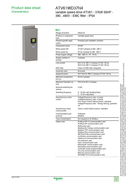
Schneider Electric ATV61 37kW 50HP 变速驱动器产品说明书
T h e i n f o r m a t i o n p r o v i d e d i n t h i s d o c u m e n t a t i o n c o n t a i n s g e n e r a l d e s c r i p t i o n s a n d /o r t e c h n i c a l c h a r a c t e r i s t i c s o f t h e p e r f o r m a n c e o f t h e p r o d u c t s c o n t a i n e d h e r e i n .T h i s d o c u m e n t a t i o n i s n o t i n t e n d e d a s a s u b s t i t u t e f o r a n d i s n o t t o b e u s e d f o r d e t e r m i n i n g s u i t a b i l i t y o r r e l i a b i l i t y o f t h e s e p r o d u c t s f o r s p e c i f i c u s e r a p p l i c a t i o n s .I t i s t h e d u t y o f a n y s u c h u s e r o r i n t e g r a t o r t o p e r f o r m t h e a p p r o p r i a t e a n d c o m p l e t e r i s k a n a l y s i s , e v a l u a t i o n a n d t e s t i n g o f t h e p r o d u c t s w i t h r e s p e c t t o t h e r e l e v a n t s p e c i f i c a p p l i c a t i o n o r u s e t h e r e o f .N e i t h e r S c h n e i d e r E l e c t r i c I n d u s t r i e s S A S n o r a n y o f i t s a f f i l i a t e s o r s u b s i d i a r i e s s h a l l b e r e s p o n s i b l e o r l i a b l e f o r m i s u s e o f t h e i n f o r m a t i o n c o n t a i n e d h e r e i n .Product data sheetCharacteristicsATV61WD37N4variable speed drive ATV61 - 37kW 50HP -380...480V - EMC filter - IP54MainRange of product Altivar 61Product or component typeVariable speed driveProduct specific appli-cationPumping and ventilation machine Component name ATV61Motor power kW 37 kW 3 phases at 380...480 V Motor power hp 50 hp 3 phases at 380...480 V Power supply voltage 380...480 V (- 15...10 %)Supply number of phases 3 phasesLine current 69.5 A for 380 V 3 phases 37 kW / 50 hp 56.8 A for 480 V 3 phases 37 kW / 50 hp EMC filter Class C2 EMC filter integrated Assembly style EnclosedApparent power 45.7 kVA for 380 V 3 phases 37 kW / 50 hp Maximum prospective line Isc22 kA 3 phases Maximum transient cur-rent78.6 A for 60 s 3 phases Nominal switching fre-quency4 kHzSwitching frequency 8...16 kHz with derating factor 2...16 kHz adjustableAsynchronous motor controlVoltage/Frequency ratio, 2 points Voltage/Frequency ratio, 5 pointsFlux vector control without sensor, standardVoltage/Frequency ratio - Energy Saving, quadratic U/fSynchronous motor control profile Vector control without sensor, standard Communication port protocolCANopen ModbusType of polarization No impedance for ModbusOption cardProfibus DP V1 communication card Profibus DP communication card Multi-pump cardModbus/Uni-Telway communication card Modbus TCP communication card Modbus Plus communication card METASYS N2 communication card LonWorks communication card Interbus-S communication card I/O extension cardFipio communication cardEthernet/IP communication card DeviceNet communication cardController inside programmable card CC-Link communication card BACnet communication cardAPOGEE FLN communication cardComplementaryProduct destination Asynchronous motorsSynchronous motorsPower supply voltage limits323...528 VPower supply frequency50...60 Hz (- 5...5 %)Power supply frequency limits47.5...63 HzContinuous output current71.5 A at 4 kHz, 380 V 3 phases65 A at 4 kHz, 460 V 3 phasesSpeed drive output frequency0.1...599 HzSpeed range 1...100 in open-loop mode, without speed feedbackSpeed accuracy+/- 10 % of nominal slip for 0.2 Tn to Tn torque variation without speed feedback Torque accuracy+/- 15 % in open-loop mode, without speed feedbackTransient overtorque130 % of nominal motor torque, +/- 10 % for 60 sBraking torque30 % without braking resistor<= 125 % with braking resistorRegulation loop Frequency PI regulatorMotor slip compensation AdjustableAutomatic whatever the loadCan be suppressedNot available in voltage/frequency ratio (2 or 5 points)Diagnostic 1 LED red presence of drive voltageOutput voltage<= power supply voltageElectrical isolation Between power and control terminalsType of cable for mounting in an enclosure Without mounting kit : 1-strand IEC cable at 45 °C, copper 90 °C XLPE/EPRWithout mounting kit : 1-strand IEC cable at 45 °C, copper 70 °C PVCWith UL Type 1 kit : 3-strand UL 508 cable at 40 °C, copper 75 °C PVCWith an IP21 or an IP31 kit : 3-strand IEC cable at 40 °C, copper 70 °C PVC Electrical connection L1/R, L2/S, L3/T, U/T1, V/T2, W/T3, PC/-, PO, PA/+, PA, PB terminal 50 mm² /AWG 1/0AI1-/AI1+, AI2, AO1, R1A, R1B, R1C, R2A, R2B, LI1...LI6, PWR terminal 2.5mm² / AWG 14Tightening torque L1/R, L2/S, L3/T, U/T1, V/T2, W/T3, PC/-, PO, PA/+, PA, PB 12 N.m / 106.2 lb.inAI1-/AI1+, AI2, AO1, R1A, R1B, R1C, R2A, R2B, LI1...LI6, PWR 0.6 N.m Supply Internal supply 24 V DC (21...27 V), <= 200 mA for overload and short-circuit pro-tectionInternal supply for reference potentiometer (1 to 10 kOhm) 10.5 V DC +/- 5 %, <=10 mA for overload and short-circuit protectionExternal supply 24 V DC (19...30 V), 30 WAnalogue input number2Analogue input type AI2 software-configurable voltage 0...10 V DC, input voltage 24 V max,impedance 30000 Ohm, resolution 11 bitsAI2 software-configurable current 0...20 mA, impedance 242 Ohm, resolution 11bitsAI1-/Al1+ bipolar differential voltage +/- 10 V DC, input voltage 24 V max, resolu-tion 11 bits + signSampling time Discrete input LI6 (if configured as logic input) 2 ms, +/- 0.5 msDiscrete input LI1...LI5 2 ms, +/- 0.5 msAnalog output AO1 2 ms, +/- 0.5 msAnalog input Al2 2 ms, +/- 0.5 msAnalog input AI1-/Al1+ 2 ms, +/- 0.5 msAbsolute accuracy precision AO1 +/- 1 % for a temperature variation 60 °CAI2 +/- 0.6 % for a temperature variation 60 °CAI1-/Al1+ +/- 0.6 % for a temperature variation 60 °CLinearity error AO1 +/- 0.2 %AI2 +/- 0.15 % of maximum valueAI1-/Al1+ +/- 0.15 % of maximum valueAnalogue output number1Analogue output type AO1 software-configurable logic output 10 V, <= 20 mAAO1 software-configurable voltage, analogue output range 0...10 V DC,impedance 470 Ohm, resolution 10 bitsAO1 software-configurable current, analogue output range 0...20 mA, impedance500 Ohm, resolution 10 bitsDiscrete output number2Discrete output type(R2A, R2B) configurable relay logic NO, electrical durability 100000 cycles(R1A, R1B, R1C) configurable relay logic NO/NC, electrical durability 100000 cy-clesMaximum response time R2A, R2B <= 7 ms, tolerance +/- 0.5 msR1A, R1B, R1C <= 7 ms, tolerance +/- 0.5 ms<= 100 ms in STO (Safe Torque Off)Minimum switching current Configurable relay logic 3 mA at 24 V DCMaximum switching current R1, R2 on resistive load, 5 A at 30 V DC, cos phi = 1, L/R = 0 msR1, R2 on resistive load, 5 A at 250 V AC, cos phi = 1, L/R = 0 msR1, R2 on inductive load, 2 A at 30 V DC, cos phi = 0.4, L/R = 7 msR1, R2 on inductive load, 2 A at 250 V AC, cos phi = 0.4, L/R = 7 ms Discrete input number7Discrete input type(PWR) safety input, 24 V DC, voltage limits <= 30 V, impedance 1500 Ohm(LI6) switch-configurable PTC probe, 0...6, impedance 1500 Ohm(LI6) switch-configurable, 24 V DC, voltage limits <= 30 V, with level 1 PLC,impedance 3500 Ohm(LI1...LI5) programmable, 24 V DC, voltage limits <= 30 V, with level 1 PLC,impedance 3500 OhmDiscrete input logic LI6 (if configured as logic input) positive logic (source), < 5 V (state 0), > 11 V(state 1)LI6 (if configured as logic input) negative logic (sink), > 16 V (state 0), < 10 V(state 1)LI1...LI5 positive logic (source), < 5 V (state 0), > 11 V (state 1)LI1...LI5 negative logic (sink), > 16 V (state 0), < 10 V (state 1) Acceleration and deceleration ramps Automatic adaptation of ramp if braking capacity exceeded, by using resistorLinear adjustable separately from 0.01 to 9000 sS, U or customizedBraking to standstill By DC injectionProtection type Motor thermal protectionMotor power removalMotor motor phase breakDrive thermal protectionDrive short-circuit between motor phasesDrive power removalDrive overvoltages on the DC busDrive overheating protectionDrive overcurrent between output phases and earthDrive line supply undervoltageDrive line supply overvoltageDrive input phase breaksDrive break on the control circuitDrive against input phase lossDrive against exceeding limit speedInsulation resistance> 1 mOhm at 500 V DC for 1 minute to earthFrequency resolution Display unit 0.1 HzAnalog input 0.024/50 HzType of connector Male SUB-D 9 on RJ45 for CANopen1 RJ45 for Modbus on terminal1 RJ45 for Modbus on front facePhysical interface2-wire RS 485 for ModbusTransmission frame RTU for ModbusTransmission rate20 kbps, 50 kbps, 125 kbps, 250 kbps, 500 kbps, 1 Mbps for CANopen9600 bps, 19200 bps for Modbus on front face4800 bps, 9600 bps, 19200 bps, 38.4 Kbps for Modbus on terminalData format8 bits, odd even or no configurable parity for Modbus on terminal8 bits, 1 stop, even parity for Modbus on front faceNumber of addresses 1...247 for Modbus1...127 for CANopenMethod of access Slave for CANopenMarking CEOperating position Vertical +/- 10 degreeProduct weight64 kgWidth285 mmHeight880 mmDepth343 mmEnvironmentNoise level64 dB conforming to 86/188/EECDielectric strength5092 V DC between control and power terminals3535 V DC between earth and power terminalsElectromagnetic compatibility Voltage dips and interruptions immunity test conforming to IEC 61000-4-11Radiated radio-frequency electromagnetic field immunity test conforming to IEC61000-4-3 level 3Electrostatic discharge immunity test conforming to IEC 61000-4-2 level 3Electrical fast transient/burst immunity test conforming to IEC 61000-4-4 level 4Conducted radio-frequency immunity test conforming to IEC 61000-4-6 level 3 Standards EN 55011 class A group 1EN 61800-3 environments 1 category C2EN 61800-3 environments 2 category C2EN/IEC 61800-3EN/IEC 61800-5-1IEC 60721-3-3 class 3C1IEC 60721-3-3 class 3S2UL Type 12Product certifications CSAC-TickDNVGOSTNOM 117ULPollution degree 3 conforming to UL 8403 conforming to EN/IEC 61800-5-1Degree of proctection IP54 conforming to UL Type 12IP54 conforming to EN/IEC 61800-5-1IP54 conforming to EN/IEC 60529Vibration resistance 1.5 mm peak to peak (f = 3...13 Hz) conforming to EN/IEC 60068-2-61 gn (f = 13...200 Hz) conforming to EN/IEC 60068-2-6Shock resistance15 gn for 11 ms conforming to EN/IEC 60068-2-27Relative humidity 5...95 % without dripping water conforming to IEC 60068-2-35...95 % without condensation conforming to IEC 60068-2-3Ambient air temperature for operation-10...50 °C with derating factor-10...40 °C without deratingAmbient air temperature for storage-25...70 °COperating altitude1000...3000 m with current derating 1 % per 100 m<= 1000 m without deratingDimensions DrawingsUL Type 12/IP 54 Drives DimensionsDimensions in mmDimensions in in.Mounting and ClearanceMounting RecommendationsDepending on the conditions in which the drive is to be used, its installation will require certain precautions and the use of appropriate accessories.Install the unit vertically:●Avoid placing it close to heating elements●Leave sufficient free space to ensure that the air required for cooling purposes can circulate from the bottom to the top of the unit. ClearanceMountingConnections and SchemaWiring Diagram Conforming to Standards EN 954-1 Category 1, IEC/EN 61508 Capacity SIL1, in Stopping Category 0 According to IEC/EN 60204-1Three-Phase Power Supply with Upstream Breaking via ContactorA1ATV61 driveKM1ContactorL1DC chokeQ1Circuit-breakerQ2GV2 L rated at twice the nominal primary current of T1Q3GB2CB05S1,XB4 B or XB5 A pushbuttonsS2T1100 VA transformer 220 V secondary(1)Line choke (three-phase); mandatory for ATV61HC11Y…HC80Y drives (except when a special transformer is used (12-pulse)).(2)For ATV61HC50N4, ATV61HC63N4 and ATV61HC50Y…HC80Y drives, refer to the power terminal connections diagram.(3)Fault relay contacts. Used for remote signalling of the drive status.(4)Connection of the common for the logic inputs depends on the positioning of the SW1 switch. The above diagram shows the internalpower supply switched to the “source” position (for other connection types, refer to the user guide).(5)There is no PO terminal on ATV61HC11Y…HC80Y drives.(6)Optional DC choke for ATV61H•••M3, ATV61HD11M3X…HD45M3X and ATV61H075N4…HD75N4 drives. Connected in place of thestrap between the PO and PA/+ terminals. For ATV61HD55M3X…HD90M3X, ATV61HD90N4…HC63N4 drives, the choke is supplied with the drive; the customer is responsible for connecting it. For ATV61W•••N4 and ATV61W•••N4C drives, the DC choke is integrated.(7)Software-configurable current (0…20 mA) or voltage (0…10 V) analog input.(8)Reference potentiometer.NOTE: All terminals are located at the bottom of the drive. Fit interference suppressors on all inductive circuits near the drive or connected on the same circuit, such as relays, contactors, solenoid valves, fluorescent lighting, etc.Wiring Diagram Conforming to Standards EN 954-1 Category 1, IEC/EN 61508 Capacity SIL1, in Stopping Category 0 According to IEC/EN 60204-1Three-Phase Power Supply with Downstream Breaking via Switch DisconnectorA1ATV61 driveL1DC chokeQ1Circuit-breakerQ2Switch disconnector (Vario)(1)Line choke (three-phase), mandatory for ATV61HC11Y…HC80Y drives (except when a special transformer is used (12-pulse)).(2)For ATV61HC50N4, ATV61HC63N4 and ATV61HC50Y…HC80Y drives, refer to the power terminal connections diagram.(3)Fault relay contacts. Used for remote signalling of the drive status.(4)Connection of the common for the logic inputs depends on the positioning of the SW1 switch. The above diagram shows the internalpower supply switched to the “source” position (for other connection types, refer to the user guide).(5)There is no PO terminal on ATV61HC11Y…HC80Y drives.(6)Optional DC choke for ATV61H•••M3, ATV61HD11M3X…HD45M3X and ATV61H075N4…HD75N4 drives. Connected in place of thestrap between the PO and PA/+ terminals. For ATV61HD55M3X…HD90M3X, ATV61HD90N4…HC63N4 drives, the choke is supplied with the drive; the customer is responsible for connecting it. For ATV61W•••N4 and ATV61W•••N4C drives, the DC choke is integrated.(7)Software-configurable current (0…20 mA) or voltage (0…10 V) analog input.(8)Reference potentiometer.NOTE: All terminals are located at the bottom of the drive. Fit interference suppressors on all inductive circuits near the drive or connected on the same circuit, such as relays, contactors, solenoid valves, fluorescent lighting, etc.Wiring Diagram Conforming to Standards EN 954-1 Category 3, IEC/EN 61508 Capacity SIL2, in Stopping Category 0 According to IEC/EN 60204-1Three-Phase Power Supply, Low Inertia Machine, Vertical MovementA1ATV61 driveA2Preventa XPS AC safety module for monitoring emergency stops and switches. One safety module can manage the “Power Removal”function for several drives on the same machine. In this case, each drive must connect its PWR terminal to its + 24 V via the safety contacts on the XPS AC module. These contacts are independent for each drive.F1FuseL1DC chokeQ1Circuit-breakerS1Emergency stop button with 2 contactsS2XB4 B or XB5 A pushbutton(1)Power supply: 24 Vdc or Vac, 115 Vac, 230 Vac.(2)S2: resets XPS AC module on power-up or after an emergency stop. ESC can be used to set external starting conditions.(3)Requests freewheel stopping of the movement and activates the “Power Removal” safety function.(4)Line choke (three-phase), mandatory for and ATV61HC11Y…HC80Y drives (except when a special transformer is used (12-pulse)).(5)The logic output can be used to signal that the machine is in a safe stop state.(6)For ATV61HC50N4, ATV61HC63N4 and ATV61HC50Y…HC80Y drives, refer to the power terminal connections diagram.(7)Fault relay contacts. Used for remote signalling of the drive status.(8)Connection of the common for the logic inputs depends on the positioning of the SW1 switch. The above diagram shows the internalpower supply switched to the “source” position (for other connection types, refer to the user guide).(9)Standardized coaxial cable, type RG174/U according to MIL-C17 or KX3B according to NF C 93-550, external diameter2.54 mm /0.09 in., maximum length 15 m / 49.21 ft. The cable shielding must be earthed.(10)There is no PO terminal on ATV61HC11Y…HC80Y drives.(11)Optional DC choke for ATV61H•••M3, ATV61HD11M3X…HD45M3X and ATV61H075N4…HD75N4 drives. Connected in place of thestrap between the PO and PA/+ terminals. For ATV61HD55M3X…HD90M3X, ATV61HD90N4…HC63N4 drives, the choke is supplied with the drive; the customer is responsible for connecting it. For ATV61W•••N4 and ATV61W•••N4C drives, the DC choke is integrated.(12)Software-configurable current (0…20 mA) or voltage (0…10 V) analog input.(13)Reference potentiometer.NOTE: All terminals are located at the bottom of the drive. Fit interference suppressors on all inductive circuits near the drive or connected on the same circuit, such as relays, contactors, solenoid valves, fluorescent lighting, etc.Wiring Diagram Conforming to Standards EN 954-1 Category 3, IEC/EN 61508 Capacity SIL2, in Stopping Category 1 According to IEC/EN 60204-1Three-Phase Power Supply, High Inertia MachineA1ATV61 driveA2 (5)Preventa XPS ATE safety module for monitoring emergency stops and switches. One safety module can manage the "Power Removal”safety function for several drives on the same machine. In this case the time delay must be adjusted on the drive controlling the motor that requires the longest stopping time. In addition, each drive must connect its PWR terminal to its + 24 V via the safety contacts on the XPS ATE module. These contacts are independent for each drive.F1FuseL1DC chokeQ1Circuit-breakerS1Emergency stop button with 2 contactsS2XB4 B or XB5 A pushbutton(1)Power supply: 24 Vdc or Vac, 115 Vac, 230 Vac.(2)Requests controlled stopping of the movement and activates the “Power Removal” safety function.(3)Line choke (three-phase), mandatory for ATV61HC11Y…HC80Y drives (except when a special transformer is used (12-pulse)).(4)S2: resets XPS ATE module on power-up or after an emergency stop. ESC can be used to set external starting conditions.(5)The logic output can be used to signal that the machine is in a safe state.(6)For stopping times requiring more than 30 seconds in category 1, use a Preventa XPS AV safety module which can provide amaximum time delay of 300 seconds.(7)For ATV61HC50N4, ATV61HC63N4 and ATV61HC50Y…HC80Y drives, refer to the power terminal connections diagram.(8)Fault relay contacts. Used for remote signalling of the drive status.(9)Connection of the common for the logic inputs depends on the positioning of the SW1 switch. The above diagram shows the internalpower supply switched to the “source” position (for other connection types, refer to the user guide).(10)Standardized coaxial cable, type RG174/U according to MIL-C17 or KX3B according to NF C 93-550, external diameter2.54 mm/0.09 in., maximum length 15 m/49.21 ft. The cable shielding must be earthed.(11)Logic inputs LI1 and LI2 must be assigned to the direction of rotation: LI1 in the forward direction and LI2 in the reverse direction.(12)There is no PO terminal on ATV61HC11Y…HC80Y drives.(13)Optional DC choke for ATV61H•••M3, ATV61HD11M3X…HD45M3X and ATV61H075N4…HD75N4 drives. Connected in place of thestrap between the PO and PA/+ terminals. For ATV61HD55M3X…HD90M3X, ATV61HD90N4…HC63N4 drives, the choke is supplied with the drive; the customer is responsible for connecting it. For ATV61W•••N4 and ATV61W•••N4C drives, the DC choke is integrated.(14)Software-configurable current (0…20 mA) or voltage (0…10 V) analog input.(15)Reference potentiometer.NOTE: All terminals are located at the bottom of the drive. Fit interference suppressors on all inductive circuits near the drive or connected on the same circuit, such as relays, contactors, solenoid valves, fluorescent lighting, etc.Product data sheet Performance Curves ATV61WD37N4Derating CurvesThe derating curves for the drive nominal current (In) depend on the temperature and the switching frequency. For intermediate temperatures(e.g. 55°C), interpolate between 2 curves.X Switching frequency。
信捷DP-508、DP-508-L步进驱动器用户手册20130420

无锡信捷电气股份有限公司资料编号DC04 20120924 1.0DP-508/DP-508-L细分驱动器用户手册1、产品概述 (1)1-1.性能特点 (1)1-2. 应用领域 (1)1-3. 电气特性 (1)2、使用指导 (2)2-1. 安全事项 (2)2-2. 连线注意点 (2)2-3. 安装环境 (2)3、接口和功能介绍 (3)3-1. 控制信号接口 (3)3-1-1. 控制信号接口功能描述 (3)3-1-2. 控制信号时序图 (3)3-1-3. 输入电路及相关要求 (4)3-2.功率接口 (4)3-2-1. 强电接口功能描述 (4)3-2-2. 供电电源要求 (5)3-2-3. 与电机接线 (5)3-3. 功能设定 (5)3-3-1. 电流设定 (6)3-3-2. 每转脉冲数设定 (6)3-4. 保护功能 (6)4、尺寸、安装及典型接线 (8)4-1.尺寸 (8)4-2.安装 (8)4-3.典型接线 (8)5、故障诊断和排除 (9)6、电机选配 (10)iDP-508/DP-508-L细分驱动器用户手册iiDP-508/DP-508-L细分驱动器用户手册细分型步进驱动器DP-508/DP-508-L最大输入电压80VDC。
输出电流5.0A,可驱动5.0A 以下各种二相混合式步进电机,该产品采用纯正弦波电流控制技术,使电机运行平稳,噪声小,特别适用于激光打标机、数控机床等分辨率较高的小型数控设备上。
1-1.性能特点⏹超低电机运行噪声⏹供电电压可达80VDC,建议不低于48VDC⏹输出电流有效值可达5.0A⏹细分动态可选,每转脉冲数最大可达40000⏹可驱动任何5.0A以下4,6,8线两相步进电机⏹光隔离信号输入⏹电流设定方便,任意档可选⏹具有过压、过流保护功能1-2. 应用领域适用于各种中小型和自动化设备及仪器,如:气动打标机、贴标机、割字机、激光打标机、绘图仪、小型雕刻机、数控机床、拿放装置等。
UPG 508 网络分析仪用户手册说明书
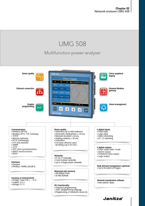
Alarm managementColour graphical displayPower qualityGraphic programmingEthernet connection5 digital outputs•Pulse output kWh / kvarh •Switch output•Threshold value output •Logic output•Pulse input •Logic input•State monitoring •HT / LT switchingPeak demand management (optional)•Up to 64 switch-off stagesNetwork visualisation software • Free GridVis ®-BasicInterfaces •Ethernet•Profibus / RS485 (DSUB-9)• T FTP•N TP (time synchronisation)•S MTP (email function)• D HCP•Energy: Class 0.2S (… / 5 A)•Current: 0.2 %• Voltage: 0.1 %Networks• IT , T N, T T networks•3 and 4-phase networks•Up to 4 single-phase networksMeasured data memory • 256 MByte Flash • 32 MB SDRAM•Unbalance•F ull wave effective value recording (up to 4.5 min.)PLC functionality•Graphical programming•Jasic ® programming language•Programming of threshold values etc.Ethernet-Modbus gatewayChapter 02UMG 508•Continuous monitoring of the power quality •Energy management systems (ISO 50001)• M aster device with Ethernet gateway for subordinate measurement points• Visualisation of the energy supply in the L VDB • A nalysis of electrical disturbances in the event of power quality problems •Cost centre analysis•Remote monitoring in the property operation •Use in test fields (e.g. in universities)Areas of applicationMain featuresHigh quality measurement with high sampling rate (20 kHz per channel)Power quality•Harmonics analysis up to 40th harmonic • Acquisition of short-term interruptions • Acquisition of transients•Display of waveforms (current and voltage)•Unbalance• Vector diagramUser -friendly, colour graphical display with intuitive user guidance •High resolution graphics display•User-friendly, self-explanatory and intuitive operation • C lear and informative representation of online graphs and further power quality eventsModern communications architecture via Ethernet•Ethernet interface and web server • F aster, better cost-optimised and more reliable communication system•High flexibility due to the use of open standards • I ntegration in PLC systems and BMS through additional interfaces • BACnet optionally availableFig.: GridVis ® – Graph setFig.: Large colour display, e.g. 12 monthly demandvaluesFig.: Illustration of the full wave effective valuesfor an eventChapter 02UMG 508Modbus Gateway function• E conomical connection of devices without Ethernet interface • I ntegration of devices with Modbus-RTU interface possible •Data can be scaled and described•Minimised number of IP addresses requiredGraphical programming•Comprehensive programming options (PLC functionality)•Jasic ® source code programming • S ustainable functional expansions far beyond pure measurement•Complete APPs from the Janitza libraryPowerful alarm management• C an be programmed via the graphic programming or Jasic ®source code• All measured values can be used•Can be arbitrarily, mathematically processed• Individual forwarding via email sending, switching of digital outputs, writing to Modbus addresses etc.• Watchdog APP• Further alarm management functions via GridVis ®-Service alarmmanagementFig.: GridVis ® topology viewFig.: The alarm management system reports events arising in good time.Fig.: Example for the configuration of currentmeasurement via 3 current transformers in a three-phase 4-wire network on the UMG 508 displayChapter 02UMG 508Typical connectionSide viewView from belowDimension diagramsAll dimensions in mmCut out: 138+0,8 x 138+0,8 mmChapter 02UMG 508Device overview and technical dataChapter 02UMG 5081 ) T he device can only determine measured values, if an L -N voltage of greater than 10 Veff or an L -L voltage of greater than 18 Veff is applied to atleast one voltage measurement input.Chapter 02UMG 508Fig.: Current and voltage measurementFig.: Connection of two electronic relays to digitaloutputs 4 and 5Comment: For detailed technical information please refer to the operation manual and the Modbus address list.。
得力DL-220D微型针式打印机用户手册 说明书

DL-220D/DL-220B用户手册V1.0安全指引请在使用本产品前仔细阅读本手册,不要执行本手册中没有明确说明的操作。
未经授权的操作会导致错误或意外。
制造商对因错误操作而导致打印机出现的任何问题均不负责。
为了避免受到电击和伤害及防止损坏打印机,在接上电源之前,务请注意以下重要事项:●仔细阅读操作手册等说明文件。
●打印机必须平放在固定的台面上。
●避免震动、碰撞、高温和阳光直射、灰尘等。
●请勿将打印机置于潮湿的环境中,请勿让雨水等任何液体沾湿打印机。
●打印机应安放在接近插座的地方,方便操作者进行电源插头的拔插操作。
●确保电源的电压值与打印机所规定的电压值一致,避免与电冰箱等大功率或有干扰的电器同一电源。
●为保证安全操作,三脚插头必须插进三孔交流电源插座中,其中地线必须有效接地。
●电源延长线必须为三芯并正确连接,以提供接地。
●若交流电源插座与打印机插头不匹配,请更换合适的交流电源插座,以保证人员、设备的安全使用。
●连接打印机通讯电缆时,请先关闭打印机和计算机的电源,选用适合的联机电缆将打印机和计算机连接起来,并锁定卡口和旋紧螺丝。
●请勿接触打印头外壳,以防止高温伤害。
●清洁打印机前,先关闭电源开关,从电源插座拔掉电源插头。
用软棉绒布沾少量中性清洁剂或酒精,轻抺打印机外部。
●如遇打印机发生故障,除认可的合格技术员外,不可擅自进行维修工作。
注:本手册内容如有更改,恕不另行通知。
目录第一章安装打印机 (4)1.1 开箱和检查 (4)1.2 放置打印机 (5)1.3 打印机部件 (6)1.4 打印机与主机连接 (7)1.5 连接电源 (8)1.6 安装纸卷 (9)1.7 安装色带 (10)1.8 安装驱动程序 (10)第二章控制面板操作 (14)2.1 指示灯 (14)2.2 走纸键 (14)第三章参数设置 (15)3.1如何进行参数设置 (15)3.2自检打印 (16)3.3系统设置 (17)3.4接口设置 (17)3.5纵向校正 (18)3.6十六进制 (18)3.7恢复出厂设置 (19)3.8安装智能助手工具 (20)第四章功能设置 (23)4.1 黑标设置 (23)4.1.1 黑标规格 (23)4.1.2 运行设置工具 (23)4.1.3 设置打印起始位置 (24)4.1.4 设置切纸位置 (25)4.1.4 设置黑标间距 (26)4.2 驱动属性设置 (26)4.2.2 钱箱设置 (26)4.2.3 黑标设置 (27)4.2.4 切刀设置 (27)第五章程序更新 (28)5.1 程序更新 (28)第六章故障处理 (30)6.1 指示灯与蜂鸣器 (30)6.2 打印错误 (30)6.3 卡纸处理 (31)6.4 清洁保养 (31)第七章规格参数与性能指标 (32)7.1 打印机规格 (32)7.2 通讯接口引脚 (33)7.2.1 USB接口 (33)7.2.2 钱箱接口 (33)7.2.3 串行接口 (34)7.2.4 并行接口 (34)7.3 电源适配器 (36)7.4 纸张规格 (37)第八章字符集 (38)8.1 通用代码页 (国际字符集: USA) (38)8.2 [PC437: USA, 欧洲标准] (39)8.3 [PC850: 多国文字] (40)8.4 [PC860: 葡萄牙文] (41)8.5 [PC863: 加拿大文-法文] (42)8.6 [PC865: 北欧文] (43)8.7 [PC858: 欧文] (44)8.8 [PC866: 古斯拉夫文 #2] (45)8.9 [KU42: 泰文] (46)8.10 [PC862: 希伯来文] (47)8.11 [PC737: 希腊文] (48)8.12 [PC864: 阿拉伯文] (49)8.13 [PC857: 土耳其文] (50)第九章指令集 (51)9.1 字符控制命令 (52)9.2 打印控制命令 (55)9.3 点图命令 (58)9.4 汉字命令 (59)9.5 黑标及切刀控制命令 (61)9.6 其他命令 (63)附录:电子信息产品污染控制的说明 (65)第一章 安装打印机1.1 开箱和检查打开纸箱,取出打印机并拆除保护材料。
欧瑞传动sd20伺服驱动器安装、调试、使用手册说明书
前言感谢您选用欧瑞传动伺服驱动器!同时,您将享受到我们为您提供的全面、真诚的服务!本手册将为您提供安装调试、操作使用、故障诊断及日常维护的有关注意事项,在安装、使用前请仔细阅读。
本手册随驱动器一起提供,请妥善保管,以备以后查阅和维护使用。
当您在使用中发现任何问题,而本手册无法为您提供解答时,请与本公司各地经销商或直接与本公司联系咨询。
我们的专业技术服务人员将竭诚为您服务,并希望您能继续选用我们的产品,敬请提出宝贵的意见和建议!内容如有改动,恕不另行通知。
版权所有,保留一切权利。
本公司致力于产品的不断改善和功能升级,手册提供资料如有变更,恕不一一通知。
最新及详细版使用手册会在公司网站()上进行公布。
开箱验货:在开箱时,请认真确认:■ 安全标识本产品的安全运行取决于正确的安装和操作以及运输与保养维护,请务必遵守本手册中使用的如下安全标识:错误的操作将引发危险情况,导致人身伤亡。
错误的操作将引发危险情况,导致轻度或中度人身伤害,损坏设备。
另外,该标识中所述事项有时也可能造成严重的后果。
驱动器外壳上标识符的意义如下:电压高,有电击危险。
表面热,禁止触摸。
■ IEC 标准本产品严格按照最新国际标准进行测试生产:IEC/EN 61800-5-1:2007—可调速电气传动系统安全要求IEC/EN 61800-3:2004/+A1:2012—可调速电气传动系统,第三部分:产品的电磁兼容性标准及其特定的试验方法敬请注意:请正确连接电子变压器线序,否则会导致危险!电子变压器通用接线方式注意危险危险本手册使用须知:■ 基本用语除特殊说明,本手册中使用如下专有名词:伺服驱动器:用来驱动和控制伺服电机。
伺服系统:伺服驱动器、伺服电机、指令控制器以及外围装置构成的伺服控制系统。
用户参数:用于监控或设定驱动器相关参数,分为监控参数和设定参数。
监控参数只能查看不能修改;设定参数可以查看和修改,并可根据作用分为功能参数和数据参数。
施耐德万高D型控制器使用说明

高字节未用
3
--
44
2C
1
故障标志2
BIT7 --空
BIT6 --空
BIT5 --空
BIT4=1 --备用合闸
BIT3=1 --常用合闸
BIT2=1 --故障锁定
BIT1=1 --备用脱扣
BIT0=1 --常用脱扣
3
常用和备用脱扣仅应用于CB级产品
45
2D
1
转换次数
3
次
46
消防联动(无源):短接此两点,机构转到双分位置,开关状态主分备分;(可靠距离10m,WTS-D800~5000系列不具备该项功能)
: 控制器的发电机启动端子在常用电源正常时常闭触点断开,当常用电源故障时常闭触点闭合以接通发电机启动电路;常开触点与之相反,请用户注意。
: 两台断路器的主回路相序必须一致。
附录1 通讯协议
D型控制器配有RS485通讯接口,可与SCADA系统、DCS系统或具有ModBus兼容的监控系统之间进行信息和数据的有效传送。通过监控系统实现对自动转换开关的“四遥”操作,
一、工作参数
通讯接口
RS-485
螺丝式固定端子,便于接线
EIA标准2线微分通讯
控制器出厂默认设置
波特率:9600,1位起始位,8位数据位,2位停止位,无校验
功能码:功能码为每次通讯传送的信息帧的第二个数据帧,告诉子机执行相应功能。本模块利用了两个指令从主机获取要执行的任务及提供的服务。
功能码
定义
03H
读数据
06H
写单个寄存器(遥控)
数据区:数据区是根据不同的功能码而不同。数据区可以是实际数值、设置点、主机发送给从机或从机发送给主机的地址。不同的数据区存储了控制器的不同工作状态及工作参数。如附录地址列表所示。
海康威视 'D5PF' 插座式驱动器系列说明书
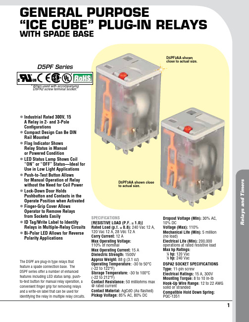
1R e l a y s a n d T i m e r sGeneral PurPose“Ice cube” PluG-In relayswIth sPade baselI ndustrial Rated 300V, 15 A Relay in 2- and 3-Pole Configurations lC ompact Design Can Be DIN Rail Mounted lF lag Indicator Shows Relay Status in Manual or Powered Condition lL ED Status Lamp Shows Coil “ON” or “OFF” Status—Ideal for Use in Low Light Applications lP ush-to-Test Button Allows for Manual Operation of Relay without the Need for Coil Power lL ock-Down Door Holds Pushbutton and Contacts in the Operate Position when Activated lF inger-Grip Cover Allows Operator to Remove Relays from Sockets Easily lI D Tag/Write Label to Identify Relays in Multiple-Relay Circuits lB i-Polar LED Allows for Reverse Polarity ApplicationsThe D5PF are plug-in type relays that feature a spade connection base. The D5PF series offer a number of enhanced features including LED status lamp, push-to-test button for manual relay operation, a convenient finger grip for removing relays and a write-on label that can be used for identifying the relay in multiple relay circuits.SPECIFICATIONS[RESISTIVE LOAD (P.F. = 1.0)]Rated Load (p.f. = 0.8): 240 Vac 12 A, 120 Vac 12 A, 28 Vdc 12 A Carry Current: 12 AMax Operating Voltage: 110% of nominalMax Operating Current: 15 A Dielectric Strength: 1500V Approx Weight: 88 g (3.1 oz)Operating Temperature: -30 to 50°C (-22 to 122°F)Storage Temperature: -30 to 100°C (-22 to 212°F)Contact Resistance: 50 milliohms max @ rated currentContact Material: AgCdO (Au flashed) Pickup Voltage: 85% AC, 80% DCDropout Voltage (Min): 30% AC, 10% DCVoltage (Max): 110%Mechanical Life (Min): 5 million (no load)Electrical Life (Min): 200,000 operations at rated resistive load Max hp Ratings: 1⁄3 hp: 120 Vac 1⁄2 hp: 240 VacD5PA2 SOCkET SPECIFICATIONS Type: 11-pin screwElectrical Ratings: 15 A, 300V Mounting Torque: 8 to 10 in-lbHook-Up Wire Range: 12 to 22 AWG solid or strandedCompatible Hold Down Spring: PQC-1351D5PF2AA shown close to actual size.D5PF3AA shown close to actual size.D5PF Series* W hen used with accompanying D5PA2 screw terminal socket.*2Three D5PF3AA, 3 PDT 11-pin relays for 120 Vac, three D5PF2-BC, DIN rail sockets with hold down spring.35.5(1.40)Tolerances: ±0.25 (±0.010) Unless Otherwise ShownD5PA2, socket, shown smaller than actual size.。
信捷产品使用知识

以DP-7022为例:
DP-系列号
70-最大输出电流(30-3.0A,50-5.0A,70-7.0A)
21-供电电压(21-220V,2-40V,8-80V)
伺服(Servo)一语源出于拉丁语的Servus(英语为Slave:奴隶)。奴隶的功用是忠实地遵从主人的命令从事劳力工作。也就是“依指令确实执行动作驱动装置;具有高精度的灵敏动作的表现,自我动作状态常时确认”。而具有这种功能的装置就称为“伺服”。
T-BOX优点:
1、支持多主多从
2、可远程上下载程序和数据监控,速度快。
3、支持多家组态,开放性更好。如:组态王和力控软件,除了它们支持modbusTCP协议的都可以.
4、传输速度快,传送数据量大。
与T-BOX的命名方式相同,由于G-BOX(无线数据传输模块)是利用GPRS进行通讯的,故称G-BOX,是MODBUS与GPRS技术的完美结合,支持232/485接口。
信捷一体机包括XP系列,XMP系列以及XMH系列。
命名规则:
以XP3-16RT-E clock为例:
XP----系列名称(XP表示是PLC与文本的结合,XMP表示PLC与MP的结合,XMH表示PLC与TH触摸屏的结合)。
3----XC系列PLC型号(1表示PLC是XC1,2表示PLC是XC2,3表示PLC是XC3)。
命名规则
A、本体:
XC系列PLC本体型号说明以XC3-32PRT-E(报价单上只罗列了NPN型,每一款都有对应的PNP型)为例:
XC3——系列号,32——I/O点数,P——输入类型(P表示PNP输入/没有P的表示NPN型输入)RT——输出类型(R表示继电器/T表示晶体管)。
E——表示供电电源(E表示220v交流供电/C表示24v直流供电)
- 1、下载文档前请自行甄别文档内容的完整性,平台不提供额外的编辑、内容补充、找答案等附加服务。
- 2、"仅部分预览"的文档,不可在线预览部分如存在完整性等问题,可反馈申请退款(可完整预览的文档不适用该条件!)。
- 3、如文档侵犯您的权益,请联系客服反馈,我们会尽快为您处理(人工客服工作时间:9:00-18:30)。
无锡信捷电气股份有限公司资料编号DC16 20131007 1.0DP-508D、DP-508D-L细分驱动器用户手册1、产品概述 (1)1-1. 性能特点 (1)1-2. 应用领域 (1)1-3. 电气特性 (1)2、使用指导 (2)2-1. 安全事项 (2)2-2. 连线注意点 (2)2-3. 安装环境 (2)3、接口和功能介绍 (3)3-1. 控制信号接口 (3)3-1-1. 控制信号接口功能描述 (3)3-1-2. 控制信号时序图 (3)3-1-3. 输入电路及相关要求 (4)3-2. 功率接口 (4)3-2-1. 强电接口功能描述 (4)3-2-2. 供电电源要求 (5)3-2-3. 与电机接线 (5)3-3. 功能设定 (5)3-3-1. 电流设定 (6)3-3-2. 细分设定 (6)3-4. 保护功能 (6)4、尺寸、安装及典型接线 (8)4-1. 尺寸 (8)4-2. 安装 (8)4-3. 典型接线 (8)5、故障诊断和排除 (10)6、电机选配 (11)iDP-508D、DP-508D-L细分驱动器用户手册iiDP-508D、DP-508D-L细分驱动器用户手册DP-508D、DP-508D-L细分型步进驱动器,最大输入电压可达80VDC,输出电流5.0A,推荐驱动5.0A以下86系列二相混合式步进电机,该产品采用纯正弦波电流控制技术,使电机运行平稳,噪声小,特别适用于激光打标机、数控机床等分辨率较高的小型数控设备上。
1-1.性能特点⏹超低电机运行噪声⏹供电电压可达80VDC⏹输出电流有效值可达5.0A⏹细分动态可选,最高达200细分⏹推荐驱动任何5.0A以下86系列两相步进电机⏹光隔离信号输入⏹电流设定方便,任意档可选⏹具有短路保护、过压保护、过流保护功能1-2. 应用领域适用于各种中小型和自动化设备及仪器,如:气动打标机、贴标机、割字机、激光打标机、绘图仪、小型雕刻机、数控机床、拿放装置等。
在用户期望低振动、小噪声、高精度、高速度的小型设备中效果尤佳。
1-3. 电气特性1DP-508D、DP-508D-L细分驱动器用户手册请于安装使用驱动器前,仔细阅读本节,并严格遵守!2-1. 安全事项⏹驱动器必须由专业技术人员进行安装和操作!⏹驱动器未接电机前严禁通电!否则可能造成触电危险,并且驱动器会报警。
⏹驱动器的输入电压必须符合技术要求!⏹严禁带电对电机或驱动器进行设置和测量!⏹驱动器必须在断电3分钟后,才能再次进行接线、安装和参数设置!⏹通电前,请确保电源电缆、电机电缆、信号电缆连接的正确性和牢固性!⏹避免电磁干扰!2-2.连线注意点⏹信号电缆和电机电缆必须带屏蔽,分别走线,距离越大,抗干扰越好。
⏹电机电缆双端屏蔽,一端接电机外壳,另一端接驱动器GND端子。
⏹严禁带电插拔输出端子,容易导致驱动器损坏。
2-3.安装环境⏹避免将驱动器安装在其他发热设备旁。
⏹避免在粉尘、油雾、腐蚀性气体、湿度太大及强震动场合使用。
⏹上位机、驱动器、电机的接地线要与地有大面积接触,确保良好的导电性,接地电阻小于2Ω。
2DP-508D、DP-508D-L细分驱动器用户手册3-1. 控制信号接口3-1-1. 控制信号接口功能描述3-1-2. 控制信号时序图为保证系统响应的可靠性,我们对各控制信号作如下要求:⏹信号高电平时要求24V有效(DP-508D-L为5V有效),低电平时要求小于0.5V有效。
⏹ENA(使能信号)应提前DIR(方向信号)至少3s变为高电平。
⏹确保DIR (方向信号) 领先PUL(脉冲信号)下降沿至少5μs建立。
⏹脉冲宽度不能小于1.2μs。
⏹脉冲低电平持续时间不能少于1.2μs。
3DP-508D 、DP-508D-L 细分驱动器用户手册4时序图具体如下:3-1-3. 输入电路及相关要求介绍驱动器输入电路的共阳极接法,示意图如下:输入要求⏹ 所有输入信号均通过光电隔离,为确保内置高速光耦可靠导通,要求提供控制信号的电流驱动能力至少8mA 。
⏹ 驱动器内部已串入光耦限流电阻,各控制信号一般接+24V (DP-508D-L 接5V )。
3-2. 功率接口3-2-1. 强电接口功能描述DP-508D 、DP-508D-L 细分驱动器用户手册53-2-2. 供电电源要求⏹ 电源电压切勿接反!⏹ 电源工作范围:35~80VDC ,保证驱动器正常工作。
⏹ 电源宜采用非稳压型直流电源,电源输出能力应大于驱动器设定电流的60%。
⏹若使用稳压型开关电源供电,电源的输出电流范围需大于电机工作电流。
3-2-3. 与电机接线注意:当驱动器与电机采取不同接线时,电机的运行效果有很大区别。
通常,驱动器的供电电压决定了电机运行的高速性能(供电电压越大,高速力矩越大,可有效避免失步),设定电流值决定了电机的输出力矩(设定电流越大,电机输出力矩越大)。
但是,供电电压大时,低速运转时的振动也较大;设定电流值大时,驱动器和电机的发热都很严重。
因此,在实际使用中,用户应根据自身需要,采取合适的连接方式,以达到满意的效果。
下图列举了几种连接方式和设定要点,仅供用户参考: ⏹ 8线并联模式:设定电流值应为电机额定电流值的1.4倍; ⏹ 8线串行模式:设定电流值应为电机额定电流值的70%;⏹ 4线、6线高速模式:设定电流值要小于或等于电机的额定电流值; ⏹ 6线高力矩模式:设定电流值应为电机额定电流值的70%。
A+A-B+B-A+A-B+B-A+A-B-NC NC A+A-NCB+NC八线电机串行接法(低速力矩大)八线电机并行接法(高速性能好)四线电机六线电机高力矩模式六线电机高速模式B-B+A+A-3-3. 功能设定驱动器采用五位拨码开关设定半流/全流和细分精度。
具体功能设定如下: SW1:设定半流/全流(SW1=OFF :半流状态;SW1=ON :全流状态); SW2~ SW5:设定细分精度。
DP-508D、DP-508D-L细分驱动器用户手册3-3-1. 电流设定用单圈电位器可设定0~5.0A之间任意电流级别,见下图所示:3-3-2. 细分设定细分精度由SW2~SW5四位拨码开关控制,详细设置如下表所示:3-4.保护功能⏹状态指示灯电源指示灯PWR:绿灯亮时,正常工作状态;报警指示灯ALM:红灯亮时,进入报警状态,说明此时出现了过压、过流或短路;红灯等间隔闪烁时,为过压报警,红灯常亮为过流或短路报警;。
⏹故障输出当驱动器出现过压、过流或短路时,由ERR、COM端子输出故障信号。
集电极开路输出。
⏹过流、过压、短路保护当电源电压大于上限电压(95V)、电机电流大于设定值的120%或者电机相线之间短路时,保护电路采取保护措施,关断PWM输出,报警指示灯给出相应报警信息。
6DP-508D、DP-508D-L细分驱动器用户手册注意:当以上保护电路动作后,驱动器无法正常工作,只有消除故障,重新上电,电源指示灯变绿后,方可使驱动器恢复。
7DP-508D 、DP-508D-L 细分驱动器用户手册84-1. 尺寸DP-508D 、DP-508D-L 外形尺寸如下图所示:4-2. 安装驱动器应安装在通风良好,防护妥善的电柜内,并定期检查散热风扇运转是否正常。
为保证驱动器散热条件,请按至少10cm 以上空间间距安装。
安装时要避免粉尘和杂物落入驱动器内部。
4-3. 典型接线单位:mmDP-508D、DP-508D-L细分驱动器用户手册注意:用户在接线时,应遵循功率线(电机相线、电源线)和弱电信号线分开的原则,以避免控制信号受到干扰。
9DP-508D、DP-508D-L细分驱动器用户手册10DP-508D、DP-508D-L细分驱动器用户手册DP-508D、DP-508D-L型适用于86系列两相混合式步进电机。
一般说来,电机的选择主要看电机扭矩和额定电流两方面。
扭矩的大小取决于电机的尺寸,尺寸大的电机扭矩也大;电流大小主要取决于电感,小电感的电流较大,电机高速运转时性能较好。
对于某一给定接法的电机来说,电机的工作电流越大,输出转矩越大,电机发热也较严重;驱动器的供电电压越大,电机高速扭矩也越大;电机高速运行时的扭矩比中低速运行时的扭矩要小。
11无锡信捷电气股份有限公司江苏省无锡市蠡园开发区滴翠路100号创意产业园7号楼四楼邮编:214072电话:(0510) 85134136传真:(0510) 85111290 WUXI XINJE ELECTRIC CO., LTD.4th Floor Building 7,Originality Industry park, Liyuan Development Zone, Wuxi City, Jiangsu Province 214072Tel: (510) 85134136Fax: (510) 85111290。