D8810终端用户手册
Model 8810A Angle Position Indicator (API) 说明书

One optional Reference supplyGENERALThis second generation API, Model 8810A, truly represents a major step forward in synchro to digital conversion technology. The use of an intelligent DSP design eliminates push buttons and allows all programming to be done either via an integrated touch-screen or a mouse interface. In addition, IEEE-488, Ethernet, and USB interfaces have been added to extend remote operation capabilities. The display can be set for one of three display modes; 0-360º, ±180°, or Degrees, Minutes, Seconds. A wide (47 Hz to 20 KHz) frequency range is standard. As an option, a programmable 2.2 VA internal reference supply can be specified.Improved flexibility is provided by two fully independent inputs that can be used to simultaneously read two separate input signals or can be combined to measure multi-speed Synchros or Resolvers. The gear ratio, for the two-speed mode, is programmable from 2:1 to 255:1Built-in phase correction eliminates errors caused by quadrature and harmonics when reference and signal are out of phase by as much as 60°.The 8810A automatically accepts and displays input voltages from 1.0 to 90 V L-L and Reference voltages from 2 to 115 Vrms over a broad frequency range of 47 Hz to 20 KHz.Therefore, one Instrument can handle most known Synchro and Resolver measurement requirements.The 8810A is a direct replacement for all variations of the previously supplied North Atlantic Industries Model 8810. Special versions (P/N = 8810 Sxxxx), contact factory to determine compatibility.Optional Reference: This design can also incorporate a 2.2 VA programmable reference generator that is used for stand alone applications (See P/N)One optional Reference supply(Drop In Replacement for NAI API Model 8810 with significant new features)One optional Reference supply SPECIFICATIONSResolution0.0001°Input Channels 2 separate isolated InputsSignal Inputs Ch.1: Synchro/Resolver programmable. 1-90V L-L auto-rangingCh.2: Synchro/Resolver programmable. 1-90V L-L auto-rangingEach channel measures the Input V L-L, Reference voltage and frequency.Data is displayed on the front panel and also available via various digital outputs. Accuracy See detailed Accuracy Specifications below.Frequency Range.Angular Range0.0000°-359.9999° or ±179.9999° programmable, or output angle can be viewed in degrees, minutes and secondsTwo-speed mode Both inputs can be combined with a ratio from 2 to 255Reference Voltage2V to 115 V auto-rangingInput Impedance Signal: >28 V L-L 200 k ; >11.8 V L-L 60k; <11.8 V L-L 13.3 kTracking Speed 2.76 rps. at 60 Hz4.68 rps. at 360 Hz or higherSettling Time 1.5 s max. for 180° step change (Based on Bandwidth selected)3.0 s max. at 47-66 Hz (Based on Bandwidth selected)Phase Correction Automatically corrects for up to a 60° phase shift between stator and rotorVelocity or DC angle for Ch.1 & Ch.2 ±1000 /sec = 10 VDC ±100 /sec = 10 VDC 0 to 359.99°= 0 -10 VDC ±179.99° = 10 VDCBand width Automatically set to 28% of frequency up to a max. of 100 Hz. User canchange this parameter as desired.Data averaging Selectable from 10 ms to 10 secondsConverter Busy TTL compatible pulses, 1µs wide nom. Pulses present when tracking. Digital Output 6 decade BCD (1-2-4-8) 10 TTL loadsSerial Interfaces Ethernet, USB, and IEEE-488, and legacy 50 pin connector Temperature Range0-50°C operatingInput Power 85 Vrms to 265 Vrms, 47 to 440 HzWeight 4 lbs.Dimensions12.5" L x 9.5" W x 3.5" HREFERENCE GENERATOR SPECIFICATIONS: Optional, see part number Voltage Output: 2 Vrms to 115 Vrms, Programmable with a resolution of 0.1 V2.0 to 9.9 Vrms / 47 Hz to 20 KHz frequency range10.0 to 27.9 Vrms / 47 Hz to 4 KHz frequency range28.0 to 115.0 Vrms / 47 Hz to 800 Hz frequency range Accuracy: 3% of settingHarmonic Content: 2.0% maximumOutput Drive: 2.2 VA (See Operation manual for detail description of Output Drive) Output Protection: Over-current and over-temperatureFrequency: 47 Hz to 20 kHz Programmable with 0.1 Hz stepsFrequency accuracy: 0.1% FSOne optional Reference supplyDETAIL ACCURACY SPECIFICATIONSAccuracy: 8810A SPECIFICATIONS APPLY AFTER A 15 MINUTE WARMUP AND CALIBRATION±0.004° from 47 Hz to 5 KHz±0.004° from 47 Hz to 1 KHz±0.004° to ±0.008° from 5 KHz to 10 KHz derated linearly±0.008° to ±0.015° from 10 KHz to 15 KHz derated linearly±0.015° to ±0.02° from 15 KHz to 20 KHz derated linearly±0.006° from 47 Hz to 5 KHz±0.006° to ±0.015° from 5 KHz to 10 KHz derated linearly±0.015° to ±0.025° from 10 KHz to 15 KHz derated linearly±0.025° to ±0.035° from 15 KHz to 20 KHz derated linearly±0.004° from 47 Hz to 1 KHzAccuracy: 8810AH SPECIFICATIONS APPLY AFTER A 15 MINUTE WARMUP AND CALIBRATION±0.0015° from 47 Hz to 5 KHz±0.002° from 47 Hz to 1 KHz±0.0015° to ±0.005° from 5 KHz to 10 KHz derated linearly±0.005° to ±0.01° from 10 KHz to 15 KHz derated linearly±0.010° to ±0.015° from 15 KHz to 20 KHz derated linearly±0.0025° from 47Hz to 5 KHz±0.0025° to ±0.01° from 5KHz to 10 KHz derated linearly±0.010° to ±0.02° from 10 KHz to 15 KHz derated linearly±0.02° to ±0.03° from 15 KHz to 20 KHz derated linearly±0.0015° from 47 Hz to 1 KHz±0.0025° from 47 Hz to 1 KHzCALIBRATIONWhen unit is turned on it will automatically initiate calibration. After warm-up of 15 minutes, unit will again automatically calibrate the channel or channels being used. Once calibrated, unit will monitor usage. Should frequency or voltage of measured signal change by more than 12.5%, unit will automatically recalibrate the channel in use. Calibration takes about 2 seconds.One optional Reference supplyINTERFACESThe 8810A is available with several different interfaces for ATE applications. Interfaces include, Ethernet, USB, IEEE-488, and a legacy 50 pin connector for API parallel BCD outputs. The legacy 50 pin connector and the IEEE-488 are both 100% backwards compatible with the model 8810. Below is information, for each interface. Detail programming commands / information are included in 8810A Programmer s Reference Guide. The Ethernet connector and the USB connector J3, are industry standard connections.(Table 4) J1 CONNECTOR, API PARALLEL PIN DESIGNATIONSDD50P, Mate DD50S or equivalentPin Designation Pin Designation Pin Designation Pin Designation Pin Designation1 *Do Not Use 11 Converter busy 21 S1 Ch.2 310.4º 41 DC out Ch.12 *Do Not Use 12 0.04º 22 S2 Ch. 2 32 2 deg. (BCD) 42 Data Freeze3 Chassis ground 13 0.01º 23 S3 Ch. 2 338 deg. (BCD) 43 Remote Ch. select4 Digital ground 14 0.8º 24 S4 Ch. 2 34Do Not Use 44 0.004º or 0.005º for5 S1 Ch. 1 15 0.2º 25 R1 Ch.2 Ref Hi 35Do Not Use 45 20 deg. (BCD)6 S2 Ch. 1 16 4º 26 R2 Ch. 2 Ref LO 36Reference Out Hi 46 40 deg. (BCD)7 S3 Ch. 1 17 1º 27 Not Data Freeze 37Reference Out Lo 47 80 deg. (BCD)8 S4 Ch. 1 18 Do Not Use 28 0.02º 380.008º 48 10 deg. (BCD)9 R1 Ch. 1 Ref HI 19 DC out Ch.2 29 0.08º 390.002 º 49 100 deg. (BCD)10R2 Ch. 1 Ref LO 20Local/Rem select300.1º400.001º or 0.005º for179.9950200º or + bit for 179.9º* Previous models allowed power input at pins 1 & 2. To meet new safety requirements, power input is ONLY via the Power Entry module.(Table 5) J2 CONNECTOR, IEEE - 488 PIN DESIGNATIONSStandard IEEE Interface ConnectorPin Designation Pin Designation1 DIO1 13 DIO52 DIO214 DIO63 DIO315 DIO74 DIO416 DIO85 EOI 17 REN6 DAV18 Gnd., DAV7 NRFD19 Gnd., NRFD8 NDAC20 Gnd., NDAC9 IFC21 Gnd., IFC10 SRQ22 Gnd., SRQ11 ATN23 Gnd., ATN12 Shield24 Gnd., LogicOne optional Reference supplyORDERING INFORMATIONPart numbers:8810A- Standard accuracy ±0.004° (See Detail Accuracy Specifications)able 2.2 VA Reference Generator8810AH- Optional high accuracy unit±0.0015° (See Detail Accuracy Specifications)ammable 2.2 VA Reference Generator NOTE: The 8810A (all models) are |ACCESSORIESIncluded with the 8810A is an accessory kit NAI part number 8810A-ACCESSORY-KIT.Kit includes the following items:Description NAI P/N50 Pin Mating connector for J1 05-0053Fuse, 5 x 20mm, 2A, slo-blo 99-0146Line Cord 202-0002Optional Mounting AccessoriesThe 8810A can be ordered with mounting adapters for mounting either one or two units in a standard 19-inch equipment rack. The table below describes full rack and tandem full rack mounting accessories.Type of Mount Description NAI P/NFull Rack Mounting Mounts one unit in 19-inch rack 783893Tandem Full Rack Mounting ½ height Mounts two units side by side in 19-inch rack548557(3-1/2" rack height)One optional Reference supply MECHANICAL OUTLINE, Model 8810AOne optional Reference supplyRevision HistoryRevision Description of Change Engineer DateA Preliminary Release FH / as 05 DEC 05A1 Preliminary Re-release FH / as 06 JAN 06B Initial Release AS 10 FEB 06C Corrected discrepancies (Resolution / accuracy) with operations manual FR 30 JUN 06D Restated accuracy specifications pg 1 & pg 3, changed operating temp. to 50 deg C max.added high accuracy P/N 8810AHFR 18 JUL 06E Updated all screen shots to latest actual units, added additional connector interfaceinformation, added Mechanical outline drawing, modified Title of document, changed file FR 07 AUG 06F Corrected Tilt stand information (standard, not optional) FR 08/11/06 F1 Deleted mouse as a purchase option, changed Ref. Generator output to 1.2VA FR 08/22/06 F2 New Address KL 04/25/07F3 Edited accuracy specifications pg 1& 3, changed Band Width statement pg.3, added pageCALIBRATION statement. Edited Part numbers re: accuracy. Changed power output ratingfor Optional reference from 1.2 VA to 2.2 VA on pgs 1, 3 & 6.FR 09/27/07F4 Added |compliant statement to page 1 & 6. FR 10/09/07 F5 Corrected minor typo. errors pages 1,3 & 4, added note re: Reference Output Drive details. FR 10/11/07G Added REF frequency characterization for voltage output, changed max REF harmoniccontent from 1% to 2% (Reference Generator Specifications pg.3).AS 11/07/07H FR 1/02/08。
Extreme_XOS_用户指导
一.使用Extreme XOS1.使用Extreme XOS1.1Extreme XOS运行平台1.BlackDiamond 108082.BlackDiamond 8810主要支持8810以下模块■ G48T module 48端口10/100/1000BASE-T RJ-45模块■ G48P module 48端口10/100/1000BASE-T 以太网供电(PoE)RJ-45模块■ G24X module 24端口1000BASE-X mini-GBIC模块■ 10G4X module 4端口10BASE-X XENPAK模块3.Summit X450系列交换机4.BlackDiamond 88061.2特征总汇1.基于802.1q和802.1p的vlan注:IEEE 802.1P 规范使得第二层交换机能够提供流量优先级和动态组播过滤服务。
优先级规范工作在媒体访问控制(MAC)帧层(OSI 参考模型第二层)。
802.1P 标准也提供了组播流量过滤功能,以确保该流量不超出第二层交换网络范围。
2.多个域的STP(Spanning Tree Protocol )3.基于策略的QoS Policy-Based Quality of Service4.无线IP路由5.IP组播6.DHCP中继DHCP/BOOTP Relay7.Extreme Standby Router Protocol (ESRP) Extreme备用路由器协议8.Ethernet Automatic Protection Switching (EAPS)以太网自动保护环交换9.Extreme Loop Recovery Protocol (ELRP)10.RIP Routing Information Protocol 版本1和版本211.RIPng 基于IPv6的RIP协议12.Open Shortest Path First (OSPF) Version 2 Routing Protocol和Version3 Routing Protocol 13.Border Gateway Protocol (BGP) version 414.DiffServ support15.Access-policy support for routing protocols访问策略的路由16.Access list support for packet filtering17.IGMP snooping to control IP multicast traffic :以IGMP侦测控制IP组播18.Protocol Independent Multicast-Dense Mode (PIM-DM)19.Protocol Independent Multicast-Sparse Mode (PIM-SM)20.Load sharing on multiple ports, across all blades多端口负载均衡21.RADIUS client and per command authentication support22.TACACS+ support23.Console command line interface (CLI) connection24.Telnet CLI connection25.Secure Shell (SSH2) connection26.Simple Network Management Protocol (SNMP) support支持简单网络管理协议27.Remote Monitoring (RMON)远程监控28.Traffic mirroring29.vMANs TM30.Network Login support31.CLEAR-Flow32.Link Layer Discovery Protocol (LLDP)33.IPv634.Link Aggregation Control Protocol (LACP)35.BGP graceful restart36.Extreme Link Status Monitor (ELSM)37.MAC-in-MAC tunneling38.Connectivity Fault Management (CFM)39.Rate-limiting40.Multiple STP (MSTP)1.3 XOS突出特点1.3.1虚拟路由器Virtual Routers(1)8810和X450系列交换机支持三个系统虚拟路由器(VR-Default, VR-Mgmt, VR-Control), BlackDiamond 10K交换机更是支持用户自己建立虚拟交换机,每个虚拟路由器有自己的独自的路由表。
MD780(G)数字车载终端使用说明书

4mmx16mm 9
自攻螺钉
3 安装支架
10 电话式听筒固定座
4.8mmx20mm 4
自攻螺钉
11 GPS天线
无键盘手持麦克风/
电源线
5
12
带键盘手持麦克风
(带保险丝)
4mmx16mm 6
自攻螺钉
13 射频天线
7 手持麦克风固定座 / /
5. 将手持麦克风或电话式听筒插头上的三角标识朝上 对准航空头接口插入,顺时针旋转航空头方向键使 其固定。
漫游状态 已开启漫游检测 已开启扰频或加密功能 已开启空口加密功能 扫描状态
扫描停留于非优先信道 扫描停留于优先信道1 扫描停留于优先信道2 已开启非专用控制信道功能
图标
产品状态
已开启声控功能
已开启监听功能
已开启扬声器 已开启静音功能 已开启音质音量优化器 已开启同频中转功能
短数据图标
图标
产品状态
接收到短消息,或者有未读短消息
该符号表示硬件界面控件名称,例如:按 【】
【PTT】键。
该符号用于对多级菜单进行逐级指引,例 > 如:选择“文件”菜单下的“新建”,表示
为:“文件 > 新建”。
包装清单
包装盒内含有以下物品。如有任何物品丢失或损坏, 请与您所购产品的经销商联系。
常规机型/集群机型
物品
数量
物品
数量
车载终端
1 固定旋钮
2
l 带 键 盘 手 持 麦 克 风: 【 TK 】 键、 【 P1】 键 和 【P2】键。
l 带键盘电话式听筒:可编程按键与车载终端的可编 程按键相同。
安装产品
注意事项
安装车载终端之前,请务必仔细阅读以下注意事项:
TD-8810快速安装指南
TD-8810/+快速安装指南使用ADSL Modem上网需要的最简单配置为:一台装有RJ45接口以太网网卡的PC、一条已开通的ADSL 宽带线路、一台TD-8810。
安装前请确认您PC的网卡可正常使用。
现在,您可以参照本指南快速配置TD-8810 PPPoE拨号上网。
一硬件安装1. 将入户电话线接入语音分离器的LINE口,电话机与分离器的PHONE口相连,ADSL Modem电话线接口与分离器MODEM口相连。
2. 把网线一端的水晶头接到ADSL Modem的LAN(RJ45)接口,另一端接到计算机网卡。
3. 连接好电源适配器,保证设备的电源打开(电源按钮按下)。
接通电源后,ADSL Modem会进行初始化,初始化完成后,LAN灯为绿色常亮,闪烁表明LAN有数据传输,如果不亮可能是网线或者网卡有问题,请进行相应的检查。
ADSL灯为绿色常亮,闪烁则代表正在与局端设备连接,请等待。
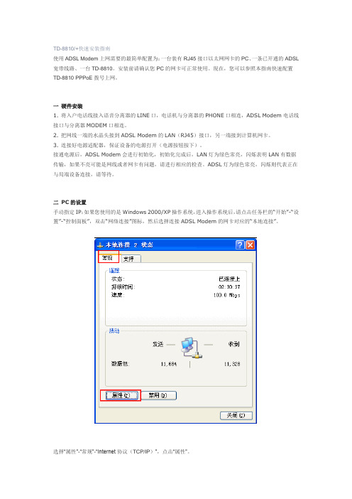
二PC的设置手动指定IP:如果您使用的是Windows 2000/XP操作系统,进入操作系统后,请点击任务栏的“开始”-“设置”-“控制面板”,双击“网络连接”图标,然后选择连接ADSL Modem的网卡对应的“本地连接”。
选择“属性”-“常规”-“Internet协议(TCP/IP)”,点击“属性”。
填入IP地址192.168.1.2,子网掩码255.255.255.0,默认网关192.168.1.1。
注意:在“使用下面的DNS服务器地址”中填入当地的DNS服务器地址,如不清楚请咨询当地服务商。
注意:若您的系统为Windows Vista,设置方法稍微不同,详细见下面说明。
手动设置Windows Vista 网络参数方法:右键桌面”网络” -“属性”,在网络管理侧边栏选择“管理网络连接”,如下图所示:然后选择连接ADSL Modem的网卡对应的“本地连接”,选择“属性”-“常规”-“Internet协议版本4(TCP/IP)”。
Dell Axim X30 用户手册说明书

型号:HC02U 、HC02U-C 、HC02U-B 、 HC02U-W 和 HD03Uw w w.d e l l.c o m | s u p p o r t.d e l l.c o mDell™ Axim™ X30用户手册注、注意和警告注:注表示可以帮助您更好地使用计算机的重要信息。
注意:注意表示可能会损坏硬件或导致数据丢失,并告诉您如何避免此类问题。
警告:警告表示可能会导致财产损失、人身伤害甚至死亡。
缩写词和缩略词有关缩写词和缩略词的完整列表,请参阅第 131 页的“词汇表”。
____________________本说明文件中的信息如有更改,恕不另行通知。
©2004Dell Inc.。
版权所有,翻印必究。
未经 Dell Inc. 书面许可,严禁以任何形式进行复制。
本文中使用的商标:Dell、DELL徽标、Axim、TrueMobile、Dimension、Inspiron、OptiPlex、Latitude、Dell Precision、PowerApp、PowerVault、PowerEdge、PowerConnect和DellNet是 Dell Inc. 的商标;Intel、Pentium和Celeron是 Intel Corporation 的注册商标,XScale和StrataFlash是 Intel Corporation 的商标;Microsoft、Windows、Windows Media 和ActiveSync是 Microsoft Corporation 的注册商标,Windows Mobile是 Microsoft Corporation 的商标;Bluetooth是Bluetooth SIG, Inc. 拥有的商标,并授权 Dell Inc. 使用。
本说明文件中述及的其它商标和产品名称是指拥有相应商标和产品名称的公司或其制造的产品。
Dell Inc. 对其它公司的商标和产品名称不拥有任何所有权。
Omega D6000系列数字传输器用户指南说明书

D6000 SERIESDigital TransmittersModbus RTU, RS-485 Output e-mail:**************For latest product manuals:Shop online at ®User’s Guide®®It is the policy of OMEGA Engineering, Inc. to comply with all worldwide safety and EMC/EMI regulations that apply. OMEGA is constantly pursuing certification of its products to the European New Approach Directives. OMEGA will add the CE mark to every appropriate device upon certification.The information contained in this document is believed to be correct, but OMEGA accepts no liability for any errors it contains, and reserves the right to alter specifications without notice.WARNING: These products are not designed for use in, and should not be used for, human applications.OverviewAll D6000 series modules contain an EEPROM (Electrically Erasable Programmable Read Only Memory) to store setup information and calibration constants. The EEPROM replaces the usual array of calibration potentiometers and DIP switches used to specify baud rate, address, parity, etc. The memory is nonvolatile which means that the information is retained even if power is removed. No batteries are used so it is not necessary to open the module case.The EEPROM provides tremendous system flexibility allowing all of the module’s setup parameters to be configured remotely through the communications port without having to physically change a switch or turn potentiometers. There is one minor drawback in using EEPROM instead of switches; there is no visual indication of the setup information in the module. To overcome this, each module has an input pin labeled DEFAULT*. By connecting this pin to Ground, the module is placed in a known communications state called Default Mode.The Default Mode settings are: 9600 baud, one start bit, eight data bits, one stop bit, and no parity. The module will only answer to Modbus Slave address “01” in the Default Mode.Grounding the DEFAULT* pin does not change any of the setups stored in EEPROM. The setup information may be read to determine all of the setup parameters stored in the module.Setup information in a module may be changed at any time or while in the Default Mode. The baud rate and parity setups may be changed without affecting the Default Mode values of 9600 baud and no parity. When the DEFAULT* pin is released, the module automatically performs an internal reset and configures itself to the baud rate and parity stored in the setup registers.The Default Mode should only be used with a single module connected to a computer in order to prevent communications data collisions with other modules on the serial port.Module ConnectionsThe D6000 series module must be connected to an RS-485 serial port for configuration. See Figure 1.0 below for an overview of the required connections. Figure 2.0 details connections between a D6000 and a A1000. Figure 3.0 details connections between a D6000 and a USB-COMi RS-485 serial converter. Note: No connections are required on the analog or digital I/O pins to perform the module configuration.Figure 1.0 General Overview, Default Mode and RS-485 Serial Connection.Figure 2.0 D6000 to A1000 RS-232 to RS-485 Serial Converter in Default Mode.Figure 3.0 D6000 to USB-COMi RS-485 Serial Converter in Default Mode.Software InstallationThe first step towards “Getting Started” with your D6000 series module is to connect the module to an RS-485 serial port using the one of the wiring connection diagrams above. Included within the wiring connections is the “Default*” line being connected to the power supply ground. This connection places the module in the “Default Mode”. The Default Mode forces the module into a known communications state and is best utilized for configuring the module. The serial communications parameters are: 9600 baud, one start bit, eight data bits, no parity and one stop bit. The module will only answer to Modbus Slave address “1” (0x01).Since the modules communicate via the Modbus RTU protocol, a Modbus Master program or the D6000 series Utility Software will be required to change the module setup register values.Modbus D6000 Series Utility Software is the best program to use when configuring a module. The utility software reads the existing module information, displays the information in easy to understand terms, allows changes to be made via drop-down list boxes and then writes the new values back to the module.The D6000 series Utility Software is provided free of charge on CDROM with a purchase order and the latest version is always downloadable from . The utility software runs on Windows based computers. Simply insert the CDROM into the CDROM drive, or download the Setup.Exe file from the website, and then run the SETUP.EXE installation file. The software will install and create a menu section called “Omega Utility Software” and the Utility Software will be under that selection.From the computer desktop select the “start” button, select “all programs”, select “Data Acquisition” and then select “D6000 Series Utility Software” to run the utility software. A desktop icon is also available to start the program. When the software opens then the first step is to select, configure and open the serial communications port on the computer that the module is connected to.Select “Serial Port” in the upper left corner of the program screen and then select the proper communications port and press the “Settings” button in the upper right hand corner of the screen.If the “Default*” line is connected to ground then select 9600 baud, no parity, eight data bits, one stop bit, RTS Only handshaking and the Tx and Rx delays can be left in their default state. Otherwise, adjust the settings to match the settings in the module.Press the “Open Port” or “Update” button to complete the serial port configuration process.Test CommunicationsAfter the utility software serial port has been configured the next step would be to check for valid communications between the computer and the module. You must have valid communications with the module before trying to perform the configuration process. To test the communications in the Default Mode, set the Modbus Slave Address to 0x01. Set the Function selector to 03 and the Register selection to 40001. Press the “Send” button to verify communications. A typical module response is shown in the figure below.The figure above illustrates Modbus function 03 being sent to Slave address 01. Both the command and response messages are displayed. This command/response format is provided for troubleshooting purposes. It displays each byte of data being sent to and received from the module. This information be a good troubleshooting tool or a good way to become familiar with the Modbus RTU protocol.The response data value from register 40001 is located in the RSP: line. The data value is a 16-bit value located in the fourth and fifth bytes in the message (00 01). The “00 01” indicates that the register value is 0001. Using the 7CH Current Input Modbus Register map, register 40001 is the Modbus Slave address. In this example the module slave address value is read back as 0001.In the event that the module was not detected by the software then the RSP: line would say “RSP: Timeout – No Response Detected!”. Several things may contribute to this problem. Some examples are no power to the module, bad RS-485 wiring connection(s), invalid port settings, or RS-485 half-duplex handshaking problems all can cause timeout errors. Timeout errors must be corrected before attempting to configure a module.Setup a ModuleAfter a successful communications test has been performed then the module can be configured. Select the type of module using the drop-down list box under “Quick Setup” in the lower left hand corner of the screen. Then press the “Setup” button. A new screen (see below) will appear that contains list of all the user-selectable module values. The screen below is for a seven channel current input module.Ensure that the Module Address in the lower left corner is 01 and then press the “Read Setup” button. The screen will now populate using the configuration data read from the module.The user-selectable values are displayed in an easy to understand format and new selections can be made using the drop-down list boxes. The drop-down list boxes make the configuration process easy and accurate because erroneous values cannot be entered.Once the new module configuration settings have been changed to meet the application requirements then press the “Apply” button to transmit the new settings.Scan Module Data ValuesAfter the module has been properly configured, the analog input data values can be polled from the module in order to verify the data from each channel. This feature is a good troubleshooting or verification tool and should only be used when valid analog input signals are connected to the module.The analog input screens contain a “Scan” button that will enable the scanning process. Each channel is read by requesting the data values from data registers within the module. The analog input data registers can be found in the Modbus Register map and the data register locations are specific to the module type.The data values are returned in unsigned integer hexadecimal percentage of Full Scale format where a value of 0x0000 represents the minus full scale input of the module. A value of 0xffff represents the positive full-scale input of the module. These values can be viewed to check that each channel is operating properly when analog signals are applied to the input terminals.The data values can also be displayed as a numerical value. The utility software knows the plus and minus full-scale input range for each channel. Using the raw hexadecimal percentage of full-scale data values the software can convert these readings to millivolts, milliamps, or temperature readings. Simply uncheck the “Display Hex Values” selection underneath the channel readings to display the numeric values.The scanning process will also log and display the highest (peak) and lowest (valley) readings that were recorded during the scanning process. This is just for indication purposes only.A scan interval slide control is also provided to speed up or slow down the scanning process. This slide control allows the channels to be scanned at intervals from 0.5 to 5 seconds.Once the setup process is completed then the D6000 is ready to be installed into the application.WARRANTY/DISCLAIMER OMEGA ENGINEERING, INC. warrants this unit to be free of defects in materials and workmanship for a period of 13 months from date of purchase. OMEGA’s WARRANTY adds an additional one (1) month grace period to the normal one (1) year product warranty to cover handling and shipping time. This ensures that OMEGA’s customers receive maximum coverage on each product.If the unit malfunctions, it must be returnedto the factory for evaluation. OMEGA’s Customer Service Department will issue an Authorized Return (AR) number immediately upon phone or written request.Upon examination by OMEGA, if the unit is found to be defective, it will be repaired or replaced at no charge. OMEGA’s WARRANTY does not apply to defects resulting from any action of the purchaser,including but not limited to mishandling, improper interfacing, operation outside of design limits, improper repair, or unauthorized modification. This WARRANTY is VOID if the unit shows evidence of having been tampered with or shows evidence of having been damaged as a result of excessive corrosion;or current, heat, moisture or vibration; improper specification; misapplication; misuse or other operating conditions outside of OMEGA’s control. Components in which wear is not warranted, include but are not limited to contact points, fuses, and triacs.OMEGA is pleased to offer suggestions on the use of its various products. However, OMEGA neither assumes responsibility for any omissions or errors nor assumes liability for any damages that result from the use of its products in accordance with information provided by OMEGA, either verbal or written. OMEGA warrants only that the parts manufactured by the company will be as specified and free of defects. OMEGA MAKES NO OTHER WARRANTIES OR REPRESENTATIONS OF ANY KIND WHATSOEVER, EXPRESSED OR IMPLIED, EXCEPT THAT OF TITLE, AND ALL IMPLIED WARRANTIES INCLUDING ANY WARRANTY OF MERCHANTABILITY AND FITNESS FOR A PARTICULAR PURPOSE ARE HEREBY DISCLAIMED. LIMITATION OF LIABILITY: The remedies of purchaser set forth herein are exclusive, and the total liability of OMEGA with respect to this order, whether based on contract, warranty, negligence, indemnification, strict liability or otherwise, shall not exceed the purchase price of the component upon which liability is based. In no event shall OMEGA be liable for consequential, incidental or special damages.CONDITIONS: Equipment sold by OMEGA is not intended to be used, nor shall it be used: (1) as a “Basic Component” under 10 CFR 21 (NRC), used in or with any nuclear installation or activity; or (2) in medical applications or used on humans. Should any Product(s) be used in or with any nuclear installation or activity, medical application, used on humans, or misused in any way, OMEGA assumes no responsibility as set forth in our basic WARRANTY /DISCLAIMER language, and, additionally, purchaser will indemnify OMEGA and hold OMEGA harmless from any liability or damage whatsoever arising out of the use of the Product(s) in such a manner.RETURN REQUESTS/INQUIRIESDirect all warranty and repair requests/inquiries to the OMEGA Customer Service Department. BEFORE RETURNING ANY PRODUCT(S) TO OMEGA, PURCHASER MUST OBTAIN AN AUTHORIZED RETURN (AR) NUMBER FROM OMEGA’S CUSTOMER SERVICE DEPARTMENT (IN ORDER TO AVOID PROCESSING DELAYS). The assigned AR number should then be marked on the outside of the return package and on any correspondence.The purchaser is responsible for shipping charges, freight, insurance and proper packaging to prevent breakage in transit.FOR WARRANTY RETURNS, please have thefollowing information available BEFOREcontacting OMEGA:1.Purchase Order number under which the productwas PURCHASED,2.Model and serial number of the product underwarranty, and3.Repair instructions and/or specific problemsrelative to the product.FOR NON-WARRANTY REPAIRS,consult OMEGA for current repair charges. Have the following information available BEFORE contacting OMEGA:1. Purchase Order number to cover the COST of the repair,2.Model and serial number of the product, and 3.Repair instructions and/or specific problems relative to the product.OMEGA’s policy is to make running changes, not model changes, whenever an improvement is possible. This affords our customers the latest in technology and engineering.OMEGA is a registered trademark of OMEGA ENGINEERING, INC.© Copyright 2010 OMEGA ENGINEERING, INC. All rights reserved. This document may not be copied, photocopied,reproduced, translated, or reduced to any electronic medium or machine-readable form, in whole or in part, without the prior written consent of OMEGA ENGINEERING, INC.Where Do I Find Everything I Need for Process Measurement and Control?OMEGA…Of Course!Shop online at TEMPERATUREⅪߜThermocouple, RTD & Thermistor Probes, Connectors, Panels & AssembliesⅪߜWire: Thermocouple, RTD & ThermistorⅪߜCalibrators & Ice Point ReferencesⅪߜRecorders, Controllers & Process MonitorsⅪߜInfrared PyrometersPRESSURE, STRAIN AND FORCEⅪߜTransducers & Strain GagesⅪߜLoad Cells & Pressure GagesⅪߜDisplacement TransducersⅪߜInstrumentation & AccessoriesFLOW/LEVELⅪߜRotameters, Gas Mass Flowmeters & Flow ComputersⅪߜAir Velocity IndicatorsⅪߜTurbine/Paddlewheel SystemsⅪߜTotalizers & Batch ControllerspH/CONDUCTIVITYⅪߜpH Electrodes, Testers & AccessoriesⅪߜBenchtop/Laboratory MetersⅪߜControllers, Calibrators, Simulators & PumpsⅪߜIndustrial pH & Conductivity EquipmentDATA ACQUISITIONⅪߜData Acquisition & Engineering SoftwareⅪߜCommunications-Based Acquisition SystemsⅪߜPlug-in Cards for Apple, IBM & CompatiblesⅪߜData Logging SystemsⅪߜRecorders, Printers & PlottersHEATERSⅪߜHeating CableⅪߜCartridge & Strip HeatersⅪߜImmersion & Band HeatersⅪߜFlexible HeatersⅪߜLaboratory HeatersENVIRONMENTALMONITORING AND CONTROLⅪߜMetering & Control InstrumentationⅪߜRefractometersⅪߜPumps & TubingⅪߜAir, Soil & Water MonitorsⅪߜIndustrial Water & Wastewater TreatmentⅪߜpH, Conductivity & Dissolved Oxygen InstrumentsMQS5046/0612。
美科星 幻影路由 D268G 无线路由器 快速安装指南说明书
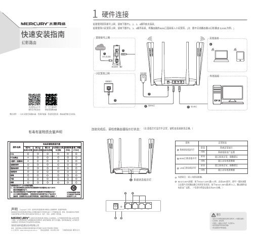
1硬件连接如果使用宽带拨号上网,请按下图中1、2、3、4顺序依次连接;如果使用小区宽带上网,请按下图中2、3、4顺序连接,将路由器的WAN口直接接入小区宽带。
(注:图中无线路由器以幻影路由 D268G为例。
)连接完成后,请检查路由器指示灯状态:(注:若指示灯显示不正常,请检查连接是否正确。
)RESET/WPS按键:按下RESET/WPS键0~1秒,启动WPS配对,即可一键快速建立设备与无线路由器之间的安全连接,按下RESET/WPS键3秒以上,路由器则会恢复出厂设置。
(*仅部分终端设备支持WPS功能。
)未经深圳市美科星通信技术有限公司明确书面许可,任何单位或个人不得擅自仿制、复制、誊抄或转译本手册部声明Copyright © 2019 深圳市美科星通信技术有限公司版权所有 , 保留所有权利。
地址:深圳市南山区高新区高新南四道023号高新工业村R1号B区第三层西段公 司 网 址: 技术支持热线:400-8810-500深圳市美科星通信技术有限公司为使用指导, 所作陈述均不构成任何形式的担保。
7108502168 REV1.0.0有毒有害物质含量声明物品清单:・11AC双频无线路由器・电源适配器・快速安装指南・路由器参数记录标贴扫一扫下载APP 轻松管理路由器关注微信公众号服务支持在身边电源接口:接入电源适配器。
已 检 验产 品 合 格 证下简称本公司)可提供有偿服务,敬请注意:三 、在国家法律法规的范围内,本承诺的解释权、修改权归深圳市美科星通信技术有限公司。
未按使用说明书要求安装、使用、维护、保管导致的产品故障或损坏;已经超出保修、保换期限; 擅自涂改、撕毁产品条形码;产品保修卡上的产品条形码或型号与产品本身不符;未经本公司许可,擅自改动产品固有的设置文件或擅自拆机修理;意外因素或人为行为导致的产品故障或损坏,如输入不合适电压、高温、进水、机械破坏、摔坏、产品严重氧化或生锈等;产品在客户发回返修途中由于运输、装卸所导致的损坏;因不可抗力如地震、火灾、水灾、雷击等导致的产品故障或损坏;其它非产品本身设计、技术、制造、质量等问题而导致的产品故障或损坏。
MDR、MTD、MVS、TMX-8810和TMX-8825移动电话装置系统板说明书

DESCRIPTIONThe System Board provides A+ switching to all boards in the MDR, MTD, MVS, TMX-8810, and TMX-8825 Mobile Radio Assemblies. Main power for the radio is routed through J1 to the System Board where it is distributed throughout the radio. A power distribution block diagram is provided in the service manual.All options for the radio are routed through the System Board and may be interconnected to the radio through option connector J905. A slotted opening is provided for the option cable at the rear of the radio adjacent to the power cable.The System Board is equipped with a public address microphone amplifier for use with the public address option when applicable (not used in MDR, MTD, TMX). This ampli-fier provides typically +20dB gain. A FET audio gate allows muting of the public address audio when the option is disabled.Speaker audio is routed through the System Board and connects to the speaker in the Front Cap Assembly via J904. An alternate speaker connection is provided on the Control Board.CIRCUIT ANALYSISPOWER DISTRIBUTIONMain power to the radio is supplied by the System Board and is interconnected to the radio by J1. An ignition sense lead provides a means for applying or removing power from the radio with the ignition switch of the vehicle. Refer to the Installation Manual for a detailed description of power con-nections.The A+ switching circuitry consists of a digital logic circuit and a power MOSFET. The low current logic circuit receives power continuously from the A+ lead from the battery to "remember" if the radio was left on or off when controlled by the ignition sense lead. C901 provides several minutes of memory when A+ is completely removed or when A+ dips to a low voltage while starting the vehicle engine.The power switch input line J902-13 is normally at 13 volts and is momentarily grounded when the power switch is pressed. This ground turns on Q901 which supplies 13 volts to the clock lead of U901. The Q output of the D-type flip-flop U901-1 alternately toggles high or low each time the clock lead goes high. R906 and C904 provide a time delay to debounce the power switch.To turn the radio on, 13 volts must be present on the ignition sense lead of J1. The power switch must toggle the Q output of U901 to the high state to prevent grounding the ignition sense voltage through D902-A. The voltage is then able to forward bias D902-B and turns on Q902. Q902 grounds the gate of MOSFET Q903. Q903 turns on, supplying switched A+ through fuse F901 to the other boards in the radio. The 3 amp fuse protects the radio and any options from high current failures.Switched A+ also feeds 8 volt regulator U902 which pro-vides voltage for the public address microphone amplifier (not used in MDR, MTD, and TMX). U903B provides a low noise 4.4 volt bias voltage to the mic amplifier U903A. The amplifier has a gain of 10 (20dB). Receiver audio from the Audio Board is attenuated 12dB by R918 and R919 and leaves the System Board on the attenuated RX audio output. When the Public Address option is turned on and the microphone is keyed, FET Q904 turns on and passes the amplified mic audio from U903A to the attenuated RX audio output. This output feeds the volume control and 3 watt audio PA on the Control Board in the Front Cap Assembly.Copyright© March 1988, General Electric CompanySYSTEM MAINTENANCE MANUALSYSTEM BOARD19D901891G1LBI-31924GOUTLINE DIAGRAM(19D901891, Sh. 1, Rev. 7)COMPONENT SIDE(19D901891, Sh. 1, Rev. 7)SOLDER SIDESYSTEM BOARD 19D901891G1LBI-31924LBI-31924 SCHEMATIC DIAGRAMSYSTEMSYSTEM BOARD19D901891G1(19D901982, Rev. 9)PARTS LISTSYMBOL PART NO.DESCRIPTIONR91019B800607P822Metal film: 8.2K ohms ±5%, 1/8 w.R911and R91219B800607P103Metal film: 10K ohms ±5%, 1/8 w.R91319B800607P104Metal film: 100K ohms ±5%, 1/8 w.R91419B800607P103Metal film: 10K ohms ±5%, 1/8 w.R91519B800607P104Metal film: 100K ohms ±5%, 1/8 w.R91619B800607P103Metal film: 10K ohms ±5%, 1/8 w.R91719B800607P104Metal film: 100K ohms ±5%, 1/8 w.R91819B800607P103Metal film: 10K ohms ±5%, 1/8 w.R91919B800607P472Metal film: 4.7K ohms ±5%, 1/8 w.- - - - - INTEGRA TED CIRCUITS - - - - -U90119A700029P9Digital: Dual Data Flip-Flop; sim to 4013B.U90219A704073P2Linear: 8 Volt Regulator; sim to MC78L08CP .U90319A700086P2Linear: Dual Op Amp; sim to 1458.- - - - - - - - - - - CABLES - - - - - - - - - -W90119C851585P1Cable.SYMBOL PART NO.DESCRIPTION- - - - - - CAP ACITORS - - - - - - - -C90119A701534P7T antalum: 10 µF ±20%, 16 VDCW.C90219A701534P4T antalum: 1 µF ±20%, 35 VDCW.C90319A702052P26Ceramic: 0.1 µF ±10%, 50 VDCW.C90419A701534P7T antalum: 10 µF ±20%, 16 VDCW.C90519A702052P14Ceramic: 0.01 µF ±10%, 50 VDCW.C90619A702052P26Ceramic: 0.1 µF ±10%, 50 VDCW.C90719A701534P4T antalum: 1 µF ± 20%, 35 VDCW.C908and C90919A700121P106Ceramic: 0.1 µF ±20%, 50 VDCW.C91019A702061P61Ceramic: 100 pF ±5%, 50 VDCW, temp coef 0 ±30 PPM.C91119A701534P4T antalum: 1 µF ±20%, 35 VDCW.C91219A702052P26Ceramic: 0.1 µF ±10%, 50 VDCW.C913thru C92419A702061P77Ceramic: 470 pF ±5%, 50 VDCW, temp coef 0 ±30 PPM.C925and C92619A702061P99Ceramic: 1000 pF ±5%, 50 VDCW,temp coef 0 ±30 PPM/°C.C927and C92819A702061P77Ceramic: 470 pF ±5%, 50 VDCW, temp coef 0 ±30 PPM.- - - - - - - - - - DIODES - - - - - - - - - -D901and D90219A703561P2Silicon, fast recovery (2 diodes in series).D903T324ADP1041Silicon: Rectifier; sim to 1N4004.D90419A703588P3Zener, transient suppressor: sim to 1N6278A.- - - - - - - - - - - FUSES - - - - - - - - - - -F90119A702169P9Enclosed link: rated 3 amps @ 125 v;sim to Littelfuse 255003.- - - - - - - - - - - JACKS - - - - - - - - - - -J90219A703248P11Post: Gold Plated, 10 mm length.J90319A705245P1Printed wire: 6 contacts, sim to Molex 10-02-1062.J904and J90519A703248P11Post: Gold Plated, 10 mm length.- - - - - - - - - - TRANSISTORS - - - - - - - --Q90119A700022P2Silicon, PNP: sim to 2N3906.Q90219A700023P2Silicon, NPN: sim to 2N3904.Q90319A705325P1MOSFET , P-Channel: sim to Seimens BUZ171.Q90419A134137P7N-type, field effect.- - - - - - - - - - RESISTORS - - - - - - - - - -R90319B800607P473Metal film: 47K ohms ±5%, 1/8 w.R90419B800607P682Metal film: 6.8K ohms ±5%, 1/8 w.R90519B800607P104Metal film: 100K ohms ±5%, 1/8 w.R90619B800607P154Metal film: 150K ohms ±5%, 1/8 w.R90719B800607P334Metal film: 330K ohms ±5%, 1/8 w.R90919B800607P223Metal film: 22K ohms ±5%, 1/8 w.SYSTEM BOARD 19D901891G1ISSUE 5PRODUCTION CHANGESChanges in the equipment to improve performance or to simplify circuits are identified by a "Revision Letter", which is stamped after the model number of the unit. The revision stamped on the unit includes all previous revisions. Refer to the Parts List for the descriptions of parts affected by these revisions.REV . A - SYSTEM BOARD 19D901891G1 Included in initial shipment.REV . B - SYSTEM BOARD 19D901891G1T o eliminate RF interference, added C927 and C928, relocated R903 and R906 and eliminated ground from printed wire board edge.REV . C - SYSTEM BOARD 19D901891G1T o provide transient protection, added D903. T o provide for Data Option added holes in RFCTS line.REV . D - SYSTEM BOARD 19D901891G1T o provide transient protection, added D904.*COMPONENTS, ADDED, DELETED, OR CHANGED BY PRODUCTION CHANGESLBI-31924IC DATASYSTEM LBI-31924Printed in U.S.A.。
- 1、下载文档前请自行甄别文档内容的完整性,平台不提供额外的编辑、内容补充、找答案等附加服务。
- 2、"仅部分预览"的文档,不可在线预览部分如存在完整性等问题,可反馈申请退款(可完整预览的文档不适用该条件!)。
- 3、如文档侵犯您的权益,请联系客服反馈,我们会尽快为您处理(人工客服工作时间:9:00-18:30)。
声明
欢迎利用升腾终端,请在第一次安装和利用前,认真阅读此用户手册。
Microsoft®是 Microsoft公司的注册商标。
Citrix®和ICA®是 Citrix公司的注册商标。
intel®是 Intel公司的注册商标。
本手册提及的所有其他产品注册商标名称都是归其相应公司所有。
未依照本手册进行操作所造成的损坏或问题,福建升腾资讯不承担任何责任。
由于自选耗材(非福建升腾资讯产品或认可产品)所造成的损坏或问题,须自行承担责任。
各型号终端产品可能与用户手册略有不同,福建升腾资讯将另行说明。
未经福建升腾资讯书面许可,不准以任何方式对本手册进行复制、转载或其它形式的侵权行为。
若是在终端的利用进程中有任何建议和意见,请随时拨打福建升腾资讯免费效劳热线:800-858-1515。
福建升腾资讯保留对本手册的最终说明权
公司简介
福建升腾资讯(简称“升腾资讯”)成立于2002年,是中国最先从事瘦客户机研发、生产和销售的企业,是国内领先的终端设备制造商。
升腾资讯专注于行业嵌入式设备的研发、制造和销售,目前产品线已覆盖了Windows终端、网络运算机(NC)、智能手持设备、自助效劳设备等嵌入式产品领域。
其中,自从1998年推出中国第一台具有自主知识产权的Windows终端——升腾2000,升腾Windows终端产品已经持续八年国内销量第一,是国内Windows终端市场当之无愧的领导厂商。
升腾资讯坚持“立足行业,面向应用”的进展战略,以行业嵌入式设备为基础,以行业应用为核心,通过技术创新、对行业客户的深切了解,为行业客户的核心业务提供“量身定做”的产品和解决方案。
目前,升腾资讯已拥有国内Windows终端厂家最丰硕的应用案例和覆盖面最广的客户群,产品普遍效劳于金融、电信、税务、电力、交通、海关、教育等行业和相关政府机构,倍受客户的认可与信任。
“创新升华价值,诚信腾飞事业”是升腾人始终不渝的理念。
升腾资讯将通过不断创新、不断超越、诚信经营,一如既往地尊重顾客需求,为顾客制造价值,提供更优质的产品和效劳!
了解更多公司信息,请访问升腾资讯网站:。
平安利用注意事项
▪非专业维修人员请勿打开终端的机壳,以幸免电击危险。
▪升腾终端采纳交流220V电源,请确保此电压与所在地域提供的交流电源电压相匹配。
▪请必然要利用带接地爱惜的三芯接地电源和插座。
若是擅自改换标准电源线,可能会带来严峻后果,责任自大。
▪请勿在未切断电源的情形下对非USB连线的设备进行插拔。
▪为延长终端的利用寿命,请尽可能幸免频繁开关机,并确保终端工作在清洁干燥的环境中。
▪请必然要注意终端利用进程中的散热问题:不要把终端摆放在阳光直射或靠近热源的地址,不要让任何物体堵塞终端机壳上的散热孔。
▪切勿将水或其他液体泼洒在终端上,一旦发生这种情形,应该当即断开终端电源。
▪请在利用进程中必然要安装好底座立式摆放,并保证电源开关在上。
拆箱检查
打开包装箱后,请依照终端的具体类型,对照下表,检查箱内的物品。
若是发觉箱内物品有缺损请及时与升腾资讯联系。
安装终端
终端概况
福建升腾资讯通太长期的自主研发和技术合作,已形成了具有自主知识产权的丰硕的Windows终端产品线,在Windows终端产品的研发、应用、技术效劳等方面均遥遥领先于其他厂商。
丰硕的产品型号、优越的产品特性,必然能最大限度地知足用户的特定需求。
产品型号预览:▪D8810 产品特性预览:
▪外观精致,操作简便
▪轻松便利的治理保护,降低企业本钱▪壮大的计算处置能力
▪壮大的网络阅读功能和多媒体播放功能▪壮大的本地平安机制和网络平安机制▪支持双启动模式
了解加倍具体的产品特性,请访问升腾资讯网站。
技术指标
实物图
D8810后面板
D8810前面板
附:后挡板图标说明:
接口名称图标(示意)直流+12V接口
视频口
鼠标口
键盘口
打印口
串口1
串口2
串口3(默认为TTL,
可跳线设置为RS232)
串口4
网口1为默认网口
网口2
USB口
利用终端
本部份要紧介绍终端的两种启动方式与串并口信号说明。
1. 终端的两种启动方式
启动方式设置:
注:请针对不同的终端型号进行启动方式的设置
按下开机电源,当显现LOGO时,长按F12键,这时系统将显现以下选择菜单:
-----------------------------------------------------------------
Boot NC
Boot NDC
HDD—0
HDD—1
USB—FDD
USB—CDROM
USB—HDD
-----------------------------------------------------------------
您能够利用上下键、空格键或回车键进行选择。
按“Enter”键,将当前选择的启动方式设置为默许启动方式,并当即以该方式启动。
假设利用本地操作系统,那么选择“Boot NC”,然后按“Enter”键确认。
假设利用远程操作系统,那么选择“Boot NDC”,然后按“Enter”键确认。
注:①终端默许从本地的存储介质中引导操作系统。
②假设显现与上面不一样的界面时,将不另行通知。
本地启动进程:
1)按下电源按钮之前,请确认所有的设备都已经正确连接;
2)按下电源按钮开启终端,终端正面的电源指示灯将由红变绿。
在网络正确连接并有
网络数据传送时,终端正面的网络传送灯将会闪烁;
3)BIOS自检完成后,终端从本地的存储介质中引导操作系统;
4)引导进程将以进度条的方式显示系统加载进度;
5)加载完毕,显示图形化界面和终端连接治理窗口;
6)此刻您能够正常利用您的终端;
7)在利用进程中,您能够利用帮忙热键(默许F1)获取终端操作的详细信息。
2. 串并口信号说明并口
串口
串口跳线说明
升腾系列终端主板内置跳线器,依如实际应用的需求,可通过更改跳线器位置改变各引脚供电电压,以兼容外接设备。
注:如须跳线,请严格对照下面的图示说明进行操作。
升腾D8810:
J1一、J12:默许一、2短接,辅口2(串口3)TTL电平;二、3短接,RS232电平。
J4:默许一、2短接,辅口1(串口2)1脚取+5V;二、3短接,不取电。
J8:默许二、3短接,辅口1(串口2)7脚不取电;一、2短接,取电+12V。
J7:默许二、3短接,辅口1(串口2)4脚不取电;一、2短接,取电+12V。
J6:默许一、2短接,辅口3(串口4)1脚取+5V;二、3短接,不取电。
J9:默许二、3短接,辅口3(串口4)4脚不取电;一、2短接,取电+12V。
J10:默许二、3短接,辅口3(串口4)7脚不取电;一、2短接,取电+12V。
J3:默许二、3短接,主口(串口1)1脚不取电;一、2短接,取电+5V。
常见故障与排除
当利用的终端显现故障,请先依照如下流程进行检查,并对照下一页的表格排除列举的几种常见故障。