OMEGA用户手册 (11)
Omega 产品用户指南说明书

e-mail:**************User’s GuideTQ504Torque TransducerShop online atINDEX1.Applications and typical attributes ...............................................Page 12.Description of the measurement system ......................................Page 12.1Mechanical design .................................................................Page 12.2Electrical design .....................................................................Page 22.3Angle-of-rotation transducer ...............................................Page 33.Electrical connection of the torque transducer ............................Page 43.1Connector pin assignments ..................................................Page 53.1.1Signals, angle outputs ...........................................................Page 63.2Laying of the output signal cables ......................................Page 63.3Placement of conductors in cable ........................................Page 64.Mechanical installation of the torque transducer........................Page 84.1Suggestions for installation ..................................................Page 85.Mechanical calibration .....................................................................Page 95.1Assembly of a simple calibrating setup............................Page 105.2Sample calculation of lever arm length.............................Page 105.3Electrical calibration.............................................................Page 116.Maintenance......................................................................................Page 117.Troubleshooting guide for transducer shaft...............................Page 12See Data Sheet for technical specificationsi1.Applications and typical attributes• Torque transducer with inductive angular position measurement system.• Measurement of constant and variable torques.• Torque measurement on a rotating shaft.• For laboratory, production and quality assurance applications.• Built- in instrument amplifier.• Built- in angle-of-rotation transducer.2.Description of the measurement system2.1Mechanical design• The transducer consists of a stator through which a bearing-mounted shaft passes.• A certain length of the shaft is utilized to convert the torque into a proportional torsional angle.• This torsional angle or angle of twist is measured between the two ends of this shaft length by an inductive (wave-form) angular position measurement system.• The inductive angular position measurement system converts the angle of twist into a proportional electrical signal.1• The electrical power for operation of the inductive angular positionmeasurement system, which rotates along with the shaft, is provided by meansof a rotary transformer.• The electrical output signal, which is proportional to the torque, is transferredto the stator by a second rotary transformer.• The connection box on the stator contains the electronics, the power supplyunit, and the instrument amplifier.2.2Electrical designThe built-in electronics comprise the following functional groups:• Oscillator for generation of the AC input voltage• Preamplifier for the output signal• Phase-sensitive rectifier for conversion of the AC output signal into a DCvoltage• Output amplifier22.3Angle-of-rotation transducer1.Rotating shaft2.Encoder disk3.Double-arm photoelectric barrier4.Open-collector output (external pull-up resistor required)*Features:• 360 slots in the encoder disk• Two double-arm photoelectric barriers 90°apart.• Number of pulses generated proportional to angle of rotation.* The ohmic value of the resistor depends on the maximum speed of rotation andthe cable length (e.g. 1500 rpm and a 4 m cable, R=3.3kΩ).33. Electrical connection of the torque transducer• Cable type: at least 12 conductors, e.g. LIYCY12 x 0.14• Max. cable length: 15 m43.1 Connector pin assignmentsDescription of interface for Type, art.-no.: 7203Angle outputs: open collector outputs with internal 10k Ωpull-up to +Vop Built in connector: Binder Series 680, type 09-0331-80-12 or equivalent Cable diagram with plugs on both sides5Top view of connector on transducer3.1.1Signals, angle outputs3.2Laying of the output signal cables-Note on safety-• Do not lay together with control lines or lines carrying a high current.• Do not lay close to strong electromagnetic fields, e.g. those of transformers,welding equipment, contactors, motors, etc.• If the above is unavoidable, the cables must be laid in grounded heavygage steel conduit.• At the transducer, lay the cables in a sling in order to prevent vibration-induced damage to them.3.3Placement of conducters in cableIn order to prevent the measurement signal being distorted by the angle pulses,the corresponding conductors should be separated within the cable.6The cable length has virtually no influence on the measurement signal, but in the case of the angle outputs the external pull-up resistances must be properly adjusted.74.Mechanical installation of the torque transducerTransducer with fixed stator:2 holes are provided in the transducer housing for this purpose.• Use displaceable couplings as both shaft ends that are capable of accommodating angular, radial and axial misalignment.• Good results have been obtained with miniature couplings stiff against torsion such as those described in data sheet 8303.At torques of 50 Nm or greater, it is also possible to install the transducer without fixed stator:• In this case, use flexible couplings at both ends.Caution:during installation no impermissibly high torques may beallowed to arise between the two ends of the torque transducer shaft.4.1Suggestions for installationTransducer with fixed stator and couplings able to accommodate angular, radial and axial misalignment at both ends.8This type of installation is possible at torques of 50 Nm and greater.5.Mechanical calibrationTo perform this, a calibration setup with lever arm and weights is needed tocreate a torque.Steps for calibration:a)Apply the rated torque to the transducer, then remove the load again.b)Precisely adjust the transducer to the zero point.c) Apply a known torque to the transducer.d) Set the indicator to the proper value.Recording of a calibration curve:a) Calibrate the transducer as described above.b) Progressively apply greater torques to the transducer in steps of 1/10 up tothe full rated torque. Then gradually remove the torque in the same way. Ateach step, wait at least 30 seconds for the torque reading to stabilize, and thenrecord.95.1A simple calibrating setup5.2Sample calculation of lever arm length10eg. m = 1 kg. Mt = 10 NmL =10Nm sec 21 kg _ 9.80665= 1,0197 m5.3Electrical calibrationA calibration control facility is integrated in the transducer to permit electrical calibration.Procedure for electrical calibration:• Remove all mechanical loads from the transducer (no torque).• Apply the calibration voltage Vc to pin K referenced to pin E.• An output signal corresponding to the rated torque will be emitted.6.Maintenance• Type IE transducers require virtually no maintenance.• The service life expectancy of the bearings within the rated temperature range is approx. 20,000 hours.• The service life expectancy of the bearing within the operating temperature range is approx. 10,000 hours.• The bearings can only be replaced in the factory.• For high-precision applications: recalibrate the transducer once annually (calibration at the factory or using an appropriate calibration setup).• Once a month, check the cable connectors to make sure that they are securely seated.• Check the cables for damage once a month.117.Troubleshooting guide for transducer shaft12ProblemProbable causesRemedial actionShaft does not rotate Bearings are defective due to:freelya) Torsional or flexional vibrations b) Excessive axial or radial loads Return to factoryc) Old or soiled bearings d) Bent shaft Zero point displacement Rotational vibration Readjust zero point on ≤2 %Shock forcesinstrument amplifier Zero offset between 2%Transducer has been overloaded The zero point can be and 5% of range Shock forcesrecalibrated once at Rotational vibrationthe instrument amplifier Transducer has Transducer has been overloaded hysteresis between by changing loads or rotational Return to factoryclockwise and counter-Rotation vibrationclockwise torqueNOTES: 13WARRANTY/DISCLAIMEROMEGA ENGINEERING, INC. warrants this unit to be free of defects in materials and workmanship for a period of 13 months from date of purchase. OMEGA’s WARRANTY adds an additional one (1) month grace period to the normal one (1) year product warranty to cover handling and shipping time. This ensures that OMEGA’s customers receive maximum coverage on each product.If the unit malfunctions, it must be returned to the factory for evaluation. OMEGA’s Customer Service Department will issue an Authorized Return (AR) number immediately upon phone or written request. Upon examination by OMEGA, if the unit is found to be defective, it will be repaired or replaced at no charge. OMEGA’s WARRANTY does not apply to defects resulting from any action of the purchaser, including but not limited to mishandling, improper interfacing, operation outside of design limits, improper repair, or unauthorized modification. This WARRANTY is VOID if the unit shows evidence of having been tampered with or shows evidence of having been damaged as a result of excessive corrosion; or current, heat, moisture or vibration; improper specification; misapplication; misuse or other operating conditions outside of OMEGA’s control. Components which wear are not warranted, including but not limited to contact points, fuses, and triacs.OMEGA is pleased to offer suggestions on the use of its various products. However, OMEGA neither assumes responsibility for any omissions or errors nor assumes liability for any damages that result from the use of its products in accordance with information provided by OMEGA, either verbal or written. OMEGA warrants only that the parts manufactured by it will be as specified and free of defects. OMEGA MAKES NO OTHER W ARRANTIES OR REPRESENTATIONS OF ANY KIND WHATSOEVER, EXPRESS OR IMPLIED, EXCEPT THAT OF TITLE, AND ALL IMPLIED WARRANTIES INCLUDING ANY WARRANTY OF MERCHANTABILITY AND FITNESS FOR A PARTICULAR PURPOSE ARE HEREBY DISCLAIMED. LIMITATION OF LIABILITY: The remedies of purchaser set forth herein are exclusive, and the total liability of OMEGA with respect to this order, whether based on contract, warranty, negligence, indemnification, strict liability or otherwise, shall not exceed the purchase price of the component upon which liability is based. In no event shall OMEGA be liable for consequential, incidental or special damages.CONDITIONS: Equipment sold by OMEGA is not intended to be used, nor shall it be used: (1) as a “Basic Component” under 10 CFR 21 (NRC), used in or with any nuclear installation or activity; or (2) in medical applications or used on humans. Should any Product(s) be used in or with any nuclear installation or activity, medical application, used on humans, or misused in any way, OMEGA assumes no responsibility as set forth in our basic WARRANTY/DISCLAIMER language, and, additionally, purchaser will indemnify OMEGA and hold OMEGA harmless from any liability or damage whatsoever arising out of the use of the Product(s) in such a manner.RETURN REQUESTS/INQUIRIESDirect all warranty and repair requests/inquiries to the OMEGA Customer Service Department. BEFORE RETU RNING ANY PRODU CT(S) TO OMEGA, PU RCHASER MU ST OBTAIN AN AU THORIZED RETU RN (AR) NU MBER FROM OMEGA’S CU STOMER SERVICE DEPARTMENT (IN ORDER TO AVOID PROCESSING DELAYS). The assigned AR number should then be marked on the outside of the return package and on any correspondence.The purchaser is responsible for shipping charges, freight, insurance and proper packaging to prevent breakage in transit.FOR WARRANTY RETURNS, please have the following information available BEFORE contacting OMEGA:1.Purchase Order number under which the productwas PURCHASED,2.Model and serial number of the product underwarranty, and3.Repair instructions and/or specific problemsrelative to the product.FOR NON-WARRANTY REPAIRS,consult OMEGA for current repair charges. Have the following information available BEFORE contacting OMEGA: 1. Purchase Order number to cover the COSTof the repair,2.Model and serial number of the product, and3.Repair instructions and/or specific problemsrelative to the product.OMEGA’s policy is to make running changes, not model changes, whenever an improvement is possible. This affords our customers the latest in technology and engineering.OMEGA is a registered trademark of OMEGA ENGINEERING, INC.© Copyright 2002 OMEGA ENGINEERING, INC. All rights reserved. This document may not be copied, photocopied, reproduced, translated, or reduced to any electronic medium or machine-readable form, in whole or in part, without the prior written consent of OMEGA ENGINEERING, INC.Where Do I Find Everything I Need for Process Measurement and Control?OMEGA…Of Course!Shop online at TEMPERATUREⅪߜThermocouple, RTD & Thermistor Probes, Connectors, Panels & AssembliesⅪߜWire: Thermocouple, RTD & ThermistorⅪߜCalibrators & Ice Point ReferencesⅪߜRecorders, Controllers & Process MonitorsⅪߜInfrared PyrometersPRESSURE, STRAIN AND FORCEⅪߜTransducers & Strain GagesⅪߜLoad Cells & Pressure GagesⅪߜDisplacement TransducersⅪߜInstrumentation & AccessoriesFLOW/LEVELⅪߜRotameters, Gas Mass Flowmeters & Flow ComputersⅪߜAir Velocity IndicatorsⅪߜTurbine/Paddlewheel SystemsⅪߜTotalizers & Batch ControllerspH/CONDUCTIVITYⅪߜpH Electrodes, Testers & AccessoriesⅪߜBenchtop/Laboratory MetersⅪߜControllers, Calibrators, Simulators & PumpsⅪߜIndustrial pH & Conductivity EquipmentDATA ACQUISITIONⅪߜData Acquisition & Engineering SoftwareⅪߜCommunications-Based Acquisition SystemsⅪߜPlug-in Cards for Apple, IBM & CompatiblesⅪߜDatalogging SystemsⅪߜRecorders, Printers & PlottersHEATERSⅪߜHeating CableⅪߜCartridge & Strip HeatersⅪߜImmersion & Band HeatersⅪߜFlexible HeatersⅪߜLaboratory HeatersENVIRONMENTALMONITORING AND CONTROLⅪߜMetering & Control InstrumentationⅪߜRefractometersⅪߜPumps & TubingⅪߜAir, Soil & Water MonitorsⅪߜIndustrial Water & Wastewater TreatmentⅪߜpH, Conductivity & Dissolved Oxygen InstrumentsM2958/0602。
Force Dimension Omega.X haptic device 用户手册说明书

USER MANUAL omega.x haptic device version 1.9Force Dimension Switzerland2summaryThe purpose of this document is>to describe the setup of the omega.x haptic device>to describe the installation of the software drivers and the Force Dimension SDK>to describe the operation modes of the omega.x haptic deviceglossarySDK refers to the Software Development Kit (SDK) for all Force Dimension products. omega.x refers to the base haptic device shared by the omega.3, omega.6 and omega.7 hap-tic devices. Unless specified, all instructions in this manual apply to all three devicetypes.34table of contents1.system overview 72.important safety instructions 83.setting up the omega.x haptic device 9 3.1unpacking the device 93.2installing the power supply 104.configuring the omega.x under Windows 11 4.1installation description 114.2installing the drivers 115.configuring the omega.x under Linux 12 5.1installing the software 12 5.2installation description 125.3installing the drivers 126.configuring the omega.x under macOS 13 6.1installing the software 13 6.2installation description 136.3installing the drivers 137.operating the omega.x 14 7.1coordinate system 14 7.2operating modes 16 7.3running the Haptic Desk program 187.4running the demonstrations programs 198.technical information - omega.3 219.technical information - omega.6 2310.technical information - omega.7 255671. system overviewfigure 1 – overview of the omega.3 haptic device1. base plate2. control unit3. front arms4. end-effector5. force button6. calibration pole7. calibration pit8. status LED 9. force LED 10. user button 11. power switch 12. power connector 13. USB connector2.important safety instructionsIMPORTANTWHEN USING THIS HAPTIC DEVICE, BASIC SAFETY PRECAUTIONSSHOULD ALWAYS BE FOLLOWED TO REDUCE THE RISKOF FIRE, ELECTRICAL SHOCK, OR PERSONAL INJURY.1.read and understand all instructions2.follow all warnings and instructions marked on your haptic device3.do not use or place your haptic device near water4.place your haptic device securely on a stable surface5.make sure that the workspace of your haptic device is free of objects6.do not overload wall outlets and extension cords as this can result in a risk of fire or electri-cal shock7.switch off your haptic device when it is not in use8.to reduce the risk of electrical shock, do not disassemble your haptic device893. setting up the omega.x haptic deviceThis section describes the different steps to follow to safely setup your omega.x haptic device before use.IMPORTANTPLEASE KEEP THE ORIGINAL PACKAGINGONLY USE THE ORIGINAL PACKAGING DURING STORING OR SHIPPING3.1 unpacking the deviceBefore unpacking the omega.x haptic device, remove the haptic device foam stabilizer and theaccessories foam section located inside the shipping box.figure 2 – view when opening the shipping box10Carefully remove the haptic device and the foam stabilizer from the box, then remove the foam stabilizer from the haptic device.figure 3 – view of the shipping box after removal of the foam stabilizer and accessoriesThe accessories compartment contains the power supply, power and USB cables, as well as the USB flash drive.figure 4 – omega.x accessories3.2 installing the power supplyPlug the power supply into the power connector. For safety purposes you should only operate your omega.x haptic device using the original Force Dimension power supply that came with your hap-tic device controller. Replacement power supplies can be ordered directly from Force Dimension.4.configuring the omega.x under WindowsThe USB driver must be first installed onto your system prior to connecting the omega.x to the computer. To do this, perform the following steps:1.plug the Force Dimension USB flash drive into your Windows computer2.open the \Windows folder on the USB flash drive and select the appropriate \32-bit or \64-bit subfolder according to the operating system version on your computer3.run the installation program and follow its instructions4.1installation descriptionThe installation program creates the following subfolders in:C:\Program Files\Force Dimension\sdk-<version>\bin subfolderThis directory contains the demonstration executables and the DLL files required to run the omega.x software. The required DLL files are also copied to the Windows system folder during the installation.\drivers subfolderThis directory contains the USB drivers required to operate your haptic device.\examples subfolderThis directory contains the demonstration programs. Example applications described in section 7.4 and come with their full source code.\doc subfolderAll documentation files and notices are located in that directory.\manuals subfolderAll hardware user manuals are located in that directory.\lib,\include subfoldersThese directories contain the files required to compile your application with the Force Dimension SDK. Please refer to the on-line programming manual for more information.4.2installing the driversUSB driversThe omega.x requires the Force Dimension USB driver. These drivers are installed automatically, and no additional step is required.5.1installing the softwareThe Force Dimension development folder must be installed onto your system before the omega.x can be used. To do this, perform the following steps:1.plug the Force Dimension USB flash drive into your Linux computer2.extract the sdk-<version>.tar.gz archive for your system architecture from the \Linuxsubfolder to the desired location (typically your home folder) by running the following com-mand within the target folder:tar –zxvf sdk-<version>.tar.gz3.this will create a sdk-<version> development folder in the target location5.2installation descriptionThe development folder contains the following directories:\bin subfolderThis directory contains the demonstration executables and the binary files required to run the omega.x software.\examples subfolderThis directory contains the demonstration programs. Example applications described in section 7.4 and come with their full source code.\doc subfolderAll documentation files and notices are located in this subfolder.\manuals subfolderAll hardware user manuals are located in that directory.\lib,\include subfoldersThese directories contain the files required to compile your application with the Force Dimension SDK. Please refer to the on-line programming manual for more information.5.3installing the driversThe Linux version of the Force Dimension SDK requires the development packages for the libusb-1.0 to be installed on your Linux distribution.IMPORTANTPLEASE NOTE THAT USB ACCESS TO THE HAPTIC DEVICE REQUIRES SUPERUSER PRIVILEDGES ON MOST LINUX DISTRIBUTIONS6.1installing the softwareThe Force Dimension development folder must be installed onto your system before the omega.x can be used. To do this, perform the following steps:1.plug the Force Dimension USB flash drive into your Apple computer2.open the sdk-<version>.dmg file for your version of macOS from the \macOS folder andextract the sdk-<version> folder to the desired location (typically your home folder) 3.this will create a sdk-<version> development folder in the target location6.2installation descriptionThe development folder contains the following directories:\bin subfolderThis directory contains the demonstration executables and the binary files required to run the omega.x software.\examples subfolderThis directory contains the demonstration programs. Example applications described in section 7.4 and come with their full source code.\doc subfolderAll documentation files and notices are located in this subfolder.\manuals subfolderAll hardware user manuals are located in that directory.\lib,\include subfoldersThese directories contain the files required to compile your application with the Force Dimension SDK. Please refer to the online programming manual for more information.6.3installing the driversThe macOS version of the Force Dimension SDK uses Apple’s native USB drivers. No further instal-lation is required.7.operating the omega.x7.1coordinate systembase translationThe position of the center of the end-effector (handle) is expressed in Cartesian coordinate and in IUS (metric) unit. Figure 5 illustrates the coordinate system.The actual origin of the coordinate system (0,0,0) is located on a virtual point situated at the cen-ter of the physical workspace of the haptic device.Z-axisY-axisX-axisfigure 5 – Cartesian coordinate system of the omega.x haptic devicewrist orientationThe omega.6 and omega.7 haptic devices incorporate a rotational wrist. The orientation of the wrist is expressed by a reference frame R wrist which is numerically represented using a 3x3 rotation matrix. This reference frame is expressed in relation to the world coordinate system described in figure 5 and is computed from the angle values returned by the joint sensors mounted of each revolute axis of the wrist.Z-axisY-axisX-axisZ-axisY-axisX-axisfigure 6 – reference frame of the wrist (omega.6 and omega.7 haptic devices)gripper angleThe angular position of the force gripper is returned in either degrees or radian.A positive angle value is returned for right-hand omega.7 haptic devices. A negative angle value is returned for left-hand haptic devices.Angular values closer to zero correspond to configurations where the force gripper is in a closed configuration. Opening of the force gripper increases the magnitude of the angle.7.2operating modesstatus indicatorsThe displays the status of the system:>LED OFF the system is off>LED ON the system is ready>LED FLASHING (fast) the system requires calibration>LED FLASHING (slow) the wrist requires manual calibration (omega.6 or omega.7)While the status LED is ON, it is possible to read the position of the of the end-effector, but no forces can be applied. Forces must be enabled by pressing the force button. When the forces are enabled, the force LED is turned ON. Forces can be disabled by pressing force button again.featurescalibrationCalibration is necessary to obtain accurate, reproducible localization of the end-effector within the workspace of the device. The omega.x is designed in such a way that there can be no drift of the calibration over time, so the procedure only needs to be performed once when the device is powered ON.The calibration procedure consists in placing calibration pole in the dedicated calibration pit. The device detects when the calibration position is reached and the status LED stops flashing. Figure 7 illustrates the calibration procedure. After the initial calibration described above, the LED will stop flashing (omega.3).figure 7 – calibration procedureOn the omega.6 and omega.7, the status LED will blink at a slower frequency, indicating that the wrist is usable but not fully calibrated. To fully calibrate the omega.6 and omega.7 wrists, each of the three rotation axes of the wrist and the grasping axis of the omega.7 must be moved by hand to their respective end-stops positions. When the device has reached all end-stops, the LED stops flashing, and the device is now fully calibrated.Alternatively, an automatic calibration procedure of the omega.x active axes can be performed by software using the Force Dimension SDK, for example by launching the application HapticInit which automatically drives the device throughout its workspace. Please do not touch the device during this automatic calibration procedure. After calibration, the device is ready for normal op-eration.gravity compensationTo prevent user fatigue and to improve dexterity during manipulation, the omega.x features gravity compensation. When gravity compensation is enabled, the weights of the arms and of the end-effector are taken into account and a vertical force is dynamically applied to the end-effector in addition to the desired user force command. Please note that gravity compensation is computed on the host computer, and therefore only gets updated every time a new force command is sent to the haptic device by the application. Gravity compensation is enabled by default and can be dis-abled through the Force Dimension SDK.forcesBy default, and when an application opens a connection to the device, the forces are disabled. Forces can be enabled or disabled at any time by pressing the force button.brakesThe device features electromagnetic brakes that can be enabled through the Force Dimension SDK. These brakes are enabled by default every time the forces are disabled. When the brakes are engaged, a viscous force is created that prevents rapid movement of the end-effector.safety featuresThe omega.x features several safety features designed to prevent uncontrolled application of forces and possible damage to the device. These safety features can be adjusted or disabled via a protected command in the Force Dimension SDK.IMPORTANTPLEASE NOTE THAT THE WARRANTY MAY NOT APPLYIF THE SAFETY FEATURES HAVE BEEN OVERRIDEN.When a connection to the omega.x haptic device is made from the computer, the forces are auto-matically disabled to avoid unexpected behaviors. The user must press the force button to enable the forces. This feature can be bypassed through the Force Dimension SDK.If the control unit detects that the velocity of the end-effector is higher than the programmed se-curity limit, the forces are automatically disabled, and the device brakes are engaged to prevent a possibly dangerous acceleration from the device. This velocity threshold can be adjusted or re-moved through the Force Dimension SDK.Please refer to the on-line programming manual for more information.7.3running the Haptic Desk programThe Haptic Desk application is available as a test and diagnostic program and offers the following capabilities:>list all Force Dimension haptic devices connected to the system>test the position reading of the haptic device in Cartesian coordinates>test all force and torque capabilities of the haptic device>run the auto-calibration procedure>read the haptic device status>read the haptic device encoder sensors individually>read the haptic device user button (if available)figure 8 – Haptic Desk test and diagnostic program7.4running the demonstrations programsTwo demonstration programs can also be used to diagnose the device. The source code and an executable file for each of these demonstration programs are provided in two separate directories named \gravity and \torus.Once the system is setup, we suggest running application gravity to check that everything is working properly and to evaluate your system's performance independently of the graphics ren-dering performance. Application torus will allow you to test the combined performance of hap-tics and graphics rendering.gravity exampleThis example program runs a best effort haptic loop to compensate for gravity. The appropriate forces are applied at any point in space to balance the device end-effector so that it is safe to let go of it. The refresh rate of the haptic loop is displayed in the console every second.figure 9 – gravity exampletorus exampleThe torus example displays an OpenGL scene with haptic feedback.figure 10 – torus examplenote – OpenGL must be installed for your compiler and development environment to compile this example. Please refer to your compiler documentation for more information, or consult 8. technical information - omega.3omega.3workspace translation ∅ 160 mm x L 110mmforces continuous 12.0 Nresolution linear < 0.01 mmdimensions height 270 mmwidth 300 mmdepth 350 mmelectronicsinterface standard USB 2.0rate up to 4.0 KHzpower universal 100V - 240Vsoftwareplatforms Microsoft WindowsLinux all distributionsApple macOSBlackberry QNXWindRiver VxWorkslibraries Haptics SDKRobotics SDKfeaturesergonomics the device can be used with both left and right handsstructure delta-based parallel kinematicsactive gravity compensationcalibration automaticdriftlessuser input 1 user buttonsafety velocity monitoringelectromagnetic damping21229.technical information - omega.6omega.6workspace translation ∅ 160 mm x L 110mmrotation 240 x 140 x 320 degforces continuous 12.0 Nresolution linear < 0.01 mmangular 0.09 degdimensions height 270 mmwidth 300 mmdepth 350 mmelectronicsinterface standard USB 2.0rate up to 4.0 KHzpower universal 100V - 240Vsoftwareplatforms Microsoft WindowsLinux all distributionsApple macOSBlackberry QNXWindRiver VxWorkslibraries Haptics SDKRobotics SDKfeaturesergonomics available in left- and right-hand configurationstructure delta-based parallel kinematicshand-centered rotation movementsdecoupling between translation and rotation movementsactive gravity compensationcalibration automaticdriftlessuser input 1 user buttonsafety velocity monitoringelectromagnetic damping232410.technical information - omega.7omega.7workspace translation ∅ 160 mm x L 110mmrotation 240 x 140 x 180 deggripper 25 mmforces continuous 12.0 Ngrasping ± 8 Nresolution linear < 0.01 mmangular 0.09 deglinear 0.006 mmdimensions height 270 mmwidth 300 mmdepth 350 mmelectronicsinterface standard USB 2.0rate up to 4.0 KHzpower universal 100V - 240Vsoftwareplatforms Microsoft WindowsLinux all distributionsApple macOSBlackberry QNXWindRiver VxWorkslibraries Haptics SDKRobotics SDKfeaturesergonomics available in left- and right-hand configurationstructure delta-based parallel kinematicshand-centered rotation movementsdecoupling between translation and rotation movementsactive gravity compensationcalibration automaticdriftlessuser input 1 simulated button using the force grippersafety velocity monitoringelectromagnetic damping252627noticeThe information in this document is provided for reference only. Force Dimension does not assume any lia-bility arising out of the application or use of the information or product described herein. This document may contain or reference information and products protected by copyrights or patents and does not convey any license under the patent rights of Force Dimension, nor the rights of others.All trademarks or trade names are properties of their respective owners.© Copyright 2020 – Force DimensionAll rights reserved.。
OMEGA 产品说明书.pdf_1718717502.332285

ACC-PS4A*
Triaxial power supply, 115 Vac power
Interface Cables Used Between Power Supply and Instrumentation
Model No. Description
ACC-CB4-15 4.6 m (15') coaxial cable (BNCM/BNCM)
Comes complete with operator’s manual.
Ordering Example: ACC-PS3A, 115 Vac powered single-channel power supply.
To order with 230 Vac power, add suffix “-230V” to model number, no additional charge.
To order without mounting feet, add suffix “-NMF” to model number, no additional charge.
K-1
Accelerometer Power Supplies/AMPLIFIERS
AC Powered, Single Channel, and TriAxial Supply
ACC-PS3A AC power supply shown smaller than actual size.
acc-ps4A
OMEGA’s ACC-PS3A is an AC-powered, single-channel, high-performance accelerometer power supply. This low-cost unit features low noise and a rugged aluminum housing with 4 easily accessible mounting holes on 121 x 44 mm (4.75 x 1.75") centers.
操作手册 Omega

安装使用说明Omega轴向中开蜗壳式离心泵本使用说明书包括基本介绍及注意事项。
在泵的安装、电路的连接及泵运行之前,请仔细阅读本说明书。
当涉及到各机组零件时,请务必参照所有其它使用说明书。
在安装的过程中,必须保证断开电源。
以免泵机组突然启动。
目录0 概述 10.0 安全 1 0.1 安全指示的标志 1 0.2 人员限定及培训 1 0.3 不遵守安全细则 1 0.4 安全意识 1 0.5 对操作人员/用户的安全细则 1 0.6 对维护、检查和安装的安全细则 2 0.7 不允许的备件制造和更换 2 0.8 不允许的工况 21.0 运输 2 1.1 安全细则 2 1.2 运输 2 1.2.1 用起吊泵机组 22.0 产品及附件介绍 2 2.1 技术特性 2 2.2 型号意义 2 2.3 零件设计 2 2.3.1 泵壳 2 2.3.2 叶轮 3 2.3.3 泵轴 3 2.3.4 轴封 3 2.3.5 轴承及润滑 3 2.4 安装形式 3 2.5 附件 3 2.6 尺寸及数量 33.0 现场安装 3 3.1 安全细则 3 3.2 装配前的检查 3 3.3 泵/机组的安装 3 3.3.1 安装(现场安装) 3 3.3.2 泵和电机带公共底座的安装 3 3.3.3 泵和电机的调整 3 3.3.4 泵转子防护装置的拆卸 4 3.4 管路连接 4 3.4.1 辅助管路 4 3.4.2 联轴器防护罩 4 3.5 最后的检查 44.0 运行运行、、启动/停机 4 4.1 运行前的检查 4 4.2 轴封 4 4.3 排气 4 4.4 运行 4 4.4.1 检查转子的转向 4 4.4.2 启动 5 4.4.3 泵工作范围 5 4.5 停机/保管/维修 5 4.5.1 新泵的保管 5 4.5.2 长期停止使用时应采取的措施 54.6 保管后的运行 65.0 维护/维修 6 5.1 一般规定 6 5.2 维护/检查 6 5.2.1 运行管理 6 5.2.2 轴封的维护 6 5.2.3 轴承的维护 6 5.3 拆卸 6 5.3.1 基本规定及建议 6 5.3.2 拆卸准备 6 5.4 重新装配7 5.5 附件/零件更换说明8 5.5.1 轴封的更换8 5.5.2 泵体密封环和叶轮密封环的更换8 5.6 一些部件的特殊说明10 5.6.1 填料密封10 5.6.2 机械密封11 5.7 备件16 5.7.1 备件的购买16 5.7.2 备件的建议17 5.7.2.1 建议备件量175.7.2.2 转子部件的互换性176.0 故障及排除18 6.1 概述186.2 故障及排除187.0日常维护及检查周期228.0 联轴器22本使用说明书包括基本介绍及注意事项。
J-11OMEGA 无线红外温度传感器说明书
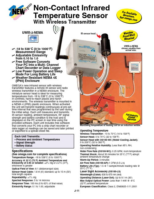
OMEGA’s new infrared sensor with wirelesstransmitter features a remote IR sensor and radio wireless transmitter in a NEMA enclosure. The miniature sensor head is ideal for measuring temperatures from -18 to 538°C (0 to 1000°F) in confined, hard-to-reach places and harshenvironments. The wireless transmitter is mounted in a NEMA 4 (IP65) plastic enclosure. When activated the unit will transmit readings continuously at pre-set time interval that was programmed by the user during the initial setup. Each unit measures and transmits: IR sensor reading, ambient temperature, RF signal strength and battery condition to the host and is displayed on the PC screen in real time using the provided software. Each unit includes free software that converts your PC into a strip chart recorder ordata logger so readings can be saved and later printed or exported to a spread sheet file.Operating TemperatureWireless Transmitter: -10 to 70°C (14 to 158°F)Sensor Head: 0 to 70°C (32 to 158°F)Sensor Head with OS100-WC (Water Cooling Jacket): 0 to 200°C (32 to 392°F)Operating Relative Humidity: Less than 95% RH, non-condensingWater Flow Rate (OS100-WC): 0.25 GPM, room temperature Thermal Shock: About 30 minutes for 25°C (77°F) abrupt ambient temperature change Warm-Up Period: 3 minutesAir Flow Rate (OS100-AP):1 CFM (0.5 L/s)Battery Life (Typ): 1.5 @ 1 sample/minute reading rate @ 25°C (77°F)Laser Sight Accessory (OS100-LS)Wavelength (Color): 630 to 670 nm (red)Operating Distance (Laser Dot): Up to 9.1 m (30')Max Output Optical Power: Less than 1 mW @ -6°C (22°F) ambient temperatureEuropean Classification: Class 2, EN60825-1/11.2001Specifications(See for complete specifications)Temperature Range: -18 to 538°C (0 to 1000°F)Accuracy @ 22°C (72°F) Ambient Temperature and Emissivity of 0.95 or Greater: ±2% rdg or 2.2°C (4°F), whichever is greaterOptical Field of View: 6:1 (distance/spot size)Sensor Head Cable: 1.8 m (6') standard; up to 15 m (50') total length capable Repeatability: ±1% rdgSpectral Response: 5 to 14 micronsResponse Time: 100 ms (0 to 63% of final value)Emissivity Range: 0.1 to 1.00, adjustableU -18 to 538°C (0 to 1000°F) Measurement Range U A djustable Emissivity from 0.10 to 1.0U F ree Software ConvertsYour PC Into a Multi- Channel Chart Recorder or Data Logger U L ow Power Operation and Sleep Mode For Long Battery Life U W eather Resistant NEMA 4X (IP65) EnclosureF C C /I n d u str y C a n a d a A p p r o v e dF o r A v ai l a b l e R e c e i v er s , S e e o me g a .c o mUWIR-2-NEMA shown smaller thanactual size.IR sensor head.W e a t h e rP r o o f /W al lM o u n t ed Non-Contact Infrared Temperature SensorWith Wireless Transmitter6:1 spot size ratioOS100-AP air purge collar to keep the lens free of particles or debris.Both shown smallerthan actual size.Maximum Operating Current: 45 mA @ 3 VdcFDA Classification: Complies with 21 CFR 1040.10, Class II laser product Beam Diameter: 5 mm (0.20")Beam Divergence: <2 mradOperating Temperature: 0 to 50°C (32 to 122°F)Operating Relative Humidity: Less than 95% RH, non-condensingbattery assembly.Ordering Examples: UWIR-2-NEMA, wireless infrared transmitter, UWTC-REC1, 48-channel USB receiver, UWTC-BATT-C, spare battery, and OS100-MB, sensor head bracket.UWIR-2-NEMA, wireless infrared transmitter, UWTC-REC2-D-MA, 48-channel transceiver/host with 1-channel 4 to 20 mA analog output, alarm and local display, UWTC-BATT-C, spare battery, and OS100-MB, sensor head bracket. OCW-3, OMEGACARE SM extends standard 1-yearwarranty to a total of 4 years.Power:(1.5 x 2")LASER RADIATION - DO NOT STARE INTO BEAM CAUTIONTYPE AND RULES PRINT BLACK 100%BACKGROUND YELLOW 100%Shown actual size.OS100-LS laser sight fits in front of the IR head for accurate positioning.。
Omega 产品说明书

e-mail:**************For latest product manuals:Shop online atUser’s Guidey = mx+bA Guide to Calibration and Unit ConversionOMB-457-0949 rev 1.0System Calibration & Engineering Units Conversion Using mx + b In many data acquisition software programs, the mx + b application is a powerful tool, which can be used to adjust displayed readings and/or values obtained from stored data. Using this software computational feature, it is possible to convert voltage readings to any more useful or appropriate engineering units, and simultaneously accomplish channel calibration to reduce or eliminate offset and gain errors. The following examples demonstrate how either or both objectives are accomplished for:•Engineering Units Conversion (1 example)•System Channel Calibration (2 examples)•Combined System Channel Calibration and Engineering Units Conversion (1 example) Engineering Units ConversionA pressure transducer with a 0-600 psi range has a 4-20mA output and is connected in a closed loop to drop 1-5 volts across a 250-ohm resistor. The theoretical nameplate relationship establishes that 1 V = 0 psi and 5 volts = 600 psi.A units conversion equation can be written in the following form:Desired Reading = m(Available Reading) + bWrite a pair of equations, representing the two known points.0 = m(1) + b (1)600 = m(5) + b (2)Solve for m by multiplying equation (1) by -1 and adding to equation (2).0 = m(1) - b600 = m(5) + b600 = m(5 - 1) (3)m = 600/(5 - 1) (4)m = 150Substitute the value for m into equation (1) to determine the value for b.0 = 150(1) + b (5)b = -150Write the correction equation using the previously determined values for m and b.Desired Reading in psi = 150(Available Reading in volts) - 150Check the result with the two original voltage readings.Correct Reading for 600 = 150(5) - 150= 600.00Correct Reading for 0 = 150(1) - 150= 0.00Any readings in the region between these two points provide the proportional psi reading as provided by the transducer.y = mx + b September 2002457-0949, rev 1.0 - 1 -System Channel Calibration(Example 1 of 2)A DBK9 and a DaqBook are connected to a precision 100.0 ohm resistor and read 0.2 °C; However, in this instance we know that 0.0 °C is the correct value. When connected to a 350.1 ohm resistor, the channel reads 719 °C. In this second instance we know that 716 °C is the correct value. From these two “points,” a correction [or calibration] equation can be derived. The equation has the mx + b form of:Correct Reading = m(Erroneous Reading) + bWrite a pair of equations, representing the two known points.0 = m(0.2) + b (1)716 = m(719) + b (2)Solve for m by multiplying equation (1) by -1 and adding to equation (2).0 = m(-0.2) - b716 = m(719) + b716 = m(719 - 0.2) (3)m = 716/(719 - 0.2) (4)m = 0.9961Substitute the value for m into equation (1) to determine the value for b.0 = 0.9961(0.2) + b (5)b = -0.1992Write the correction equation using the previously determined values for m and b.Correct Reading = 0.9961(Erroneous Reading) - 0.1992Check the result with the two original erroneous values.Correct Reading for 716 = 0.9961(719) - 0.1992= 715.99Correct Reading for 0 = 0.9961(0.2) - 0.1992= 0.00002Any readings in the region of these two points should be much more accurate after being adjusted by the correction equation. -2- 457-0949, rev 1.0September 2002y = mx + bSystem Channel Calibration(Example 2 of 2)A DBK8 and a DaqBook are configured for a 50 volt range. Shorting the inputs together delivers a reading of 0.022 volts and applying a DC calibrator set at 47.5 volts produces a reading of 48.3 volts. From these two “points” a correction or calibration equation can be derived which has the form:Correct Reading = m(Erroneous Reading) + bWrite a pair of equations, representing the two known points.0 = m(0.022) + b (1)47.5 = m(48.3) + b (2)Solve for m by multiplying equation (1) by -1 and adding to equation (2).0 = m(-0.022) - b47.5= m(48.3) + b47.5 = m(48.3 - 0.022) (3)m = 47.5/(48.3 - 0.022) (4)m = 0.9839Substitute the value for m into equation (1) to determine the value for b.0 = 0.9839(0.022) + b (5)b = -0.0216Write the correction equation using the previously determined values for m and b.Correct Reading = 0.9839(Erroneous Reading) - 0.0216Check the result with the two original erroneous values.Correct Reading for 47.5 = 0.9839(48.3) - 0.0216= 47.501Correct Reading for 0 = 0.9839(0.022) - 0.0216= 0.00004Any readings in the region of these two points should be much more accurate after being adjusted by the correction equation. y = mx + b09-13-023Combined System Channel Calibration and Engineering Units Conversion A DBK15 and a DaqBook are connected to a string pot to measure the open position of a vertical bay door. When the door is closed, the voltage reading given by the DaqBook is 0.175 volts. When the door is raised to a height of 12 feet, the voltage reading provided by the DaqBook is 4.572 volts. From these two “points” a correction [or calibration] equation can be derived which has the form:Correct Reading = m(Erroneous Reading) + bWrite a pair of equations, representing the two known points.0 = m(0.175) + b (1)12 = m(4.572) + b (2)Solve for m by multiplying equation (1) by -1 and adding to equation (2).0 = m(-0.175) - b12 = m(4.572) + b12 = m(4.572 - 0.175) (3)m = 12/(4.572 - 0.175) (4)m = 2.729Substitute the value for m into equation (1) to determine the value for b.0 = 2.729 (0.175) + b (5)b = -0.478Write the correction equation using the previously determined values for m and b.Correct Reading = 2.729(Erroneous Reading) - 0.478Check the result with the two original erroneous values.Correct Reading for 12 = 2.729(4.572) - 0.478= 12.00Correct Reading for 0 = 2.729(0.175) - 0.478= 0.00Any readings in the region of these two points should be much more accurate after being adjusted by the correction equation. -4- 457-0949, rev 1.0September 2002y = mx + bWARRANTY/DISCLAIMEROMEGA ENGINEERING, INC. warrants this unit to be free of defects in materials and workmanship for a period of 13 months from date of purchase. OMEGA’s WARRANTY adds an additional one (1) month grace period to the normal one (1) year product warranty to cover handling and shipping time. This ensures that OMEGA’s customers receive maximum coverage on each product.If the unit malfunctions, it must be returned to the factory for evaluation. OMEGA’s Customer Service Department will issue an Authorized Return (AR) number immediately upon phone or written request. Upon examination by OMEGA, if the unit is found to be defective, it will be repaired or replaced at no charge. OMEGA’s WARRANTY does not apply to defects resulting from any action of the purchaser, including but not limited to mishandling, improper interfacing, operation outside of design limits, improper repair, or unauthorized modification. This WARRANTY is VOID if the unit shows evidence of having been tampered with or shows evidence of having been damaged as a result of excessive corrosion; or current, heat, moisture or vibration; improper specification; misapplication; misuse or other operating conditions outside of OMEGA’s control. Components in which wear is not warranted, include but are not limited to contact points, fuses, and triacs.OMEGA is pleased to offer suggestions on the use of its various products. However, OMEGA neither assumes responsibility for any omissions or errors nor assumes liability for any damages that result from the use of its products in accordance with information provided by OMEGA, either verbal or written. OMEGA warrants only that the parts manufactured by the company will be as specified and free of defects. OMEGA MAKES NO OTHER WARRANTIES OR REPRESENTATIONS OF ANY KIND WHATSOEVER, EXPRESSED OR IMPLIED, EXCEPT THAT OF TITLE, AND ALL IMPLIED WARRANTIES INCLUDING ANY WARRANTY OF MERCHANTABILITY AND FITNESS FOR A PARTICULAR PURPOSE ARE HEREBY DISCLAIMED. LIMITATION OF LIABILITY: The remedies of purchaser set forth herein are exclusive, and the total liability of OMEGA with respect to this order, whether based on contract, warranty, negligence, indemnification, strict liability or otherwise, shall not exceed the purchase price of the component upon which liability is based. In no event shall OMEGA be liable for consequential, incidental or special damages.CONDITIONS: Equipment sold by OMEGA is not intended to be used, nor shall it be used: (1) as a “Basic Component” under 10 CFR 21 (NRC), used in or with any nuclear installation or activity; or (2) in medical applications or used on humans. Should any Product(s) be used in or with any nuclear installation or activity, medical application, used on humans, or misused in any way, OMEGA assumes no responsibility as set forth in our basic WARRANTY/DISCLAIMER language, and, additionally, purchaser will indemnify OMEGA and hold OMEGA harmless from any liability or damage whatsoever arising out of the use of the Product(s) in such a manner.RETURN REQUESTS/INQUIRIESDirect all warranty and repair requests/inquiries to the OMEGA Customer Service Department. BEFORE RETURNING ANY PRODUCT(S) TO OMEGA, PURCHASER MUST OBTAIN AN AUTHORIZED RETURN (AR) NUMBER FROM OMEGA’S CUSTOMER SERVICE DEPARTMENT (IN ORDER TO AVOID PROCESSING DELAYS). The assigned AR number should then be marked on the outside of the return package and on any correspondence.The purchaser is responsible for shipping charges, freight, insurance and proper packaging to prevent breakage in transit.FOR WARRANTY RETURNS, please have the following information available BEFORE contacting OMEGA:1.Purchase Order number under which the productwas PURCHASED,2.Model and serial number of the product underwarranty, and3.Repair instructions and/or specific problemsrelative to the product.FOR NON-WARRANTY REPAIRS,consult OMEGA for current repair charges. Have the following information available BEFORE contacting OMEGA: 1. Purchase Order number to cover the COSTof the repair,2.Model and serial number of the product, and3.Repair instructions and/or specific problemsrelative to the product.OMEGA’s policy is to make running changes, not model changes, whenever an improvement is possible. This affords our customers the latest in technology and engineering.OMEGA is a registered trademark of OMEGA ENGINEERING, INC.© Copyright 2006OMEGA ENGINEERING, INC. All rights reserved. This document may not be copied, photocopied, reproduced, translated, or reduced to any electronic medium or machine-readable form, in whole or in part, without the prior written consent of OMEGA ENGINEERING, INC.Where Do I Find Everything I Need for Process Measurement and Control?OMEGA…Of Course!Shop online at TEMPERATUREⅪߜThermocouple, RTD & Thermistor Probes, Connectors, Panels & AssembliesⅪߜWire: Thermocouple, RTD & ThermistorⅪߜCalibrators & Ice Point ReferencesⅪߜRecorders, Controllers & Process MonitorsⅪߜInfrared PyrometersPRESSURE, STRAIN AND FORCEⅪߜTransducers & Strain GagesⅪߜLoad Cells & Pressure GagesⅪߜDisplacement TransducersⅪߜInstrumentation & AccessoriesFLOW/LEVELⅪߜRotameters, Gas Mass Flowmeters & Flow ComputersⅪߜAir Velocity IndicatorsⅪߜTurbine/Paddlewheel SystemsⅪߜTotalizers & Batch ControllerspH/CONDUCTIVITYⅪߜpH Electrodes, Testers & AccessoriesⅪߜBenchtop/Laboratory MetersⅪߜControllers, Calibrators, Simulators & PumpsⅪߜIndustrial pH & Conductivity EquipmentDATA ACQUISITIONⅪߜData Acquisition & Engineering SoftwareⅪߜCommunications-Based Acquisition SystemsⅪߜPlug-in Cards for Apple, IBM & CompatiblesⅪߜDatalogging SystemsⅪߜRecorders, Printers & PlottersHEATERSⅪߜHeating CableⅪߜCartridge & Strip HeatersⅪߜImmersion & Band HeatersⅪߜFlexible HeatersⅪߜLaboratory HeatersENVIRONMENTALMONITORING AND CONTROLⅪߜMetering & Control InstrumentationⅪߜRefractometersⅪߜPumps & TubingⅪߜAir, Soil & Water MonitorsⅪߜIndustrial Water & Wastewater TreatmentⅪߜpH, Conductivity & Dissolved Oxygen InstrumentsM4347/0606。
欧米茄表使用说明书
如何确定我购买的是正宗欧米茄腕表?遵循如下步骤可以确定您购买的是正宗欧米茄腕表:- 只在欧米茄指定经销商处购买欧米茄腕表。
- 申请一张信用卡大小的保修卡,完整填写8位系列编号、手表编号以及经销商的完整姓名和地址。
- 如果您想确定腕表是否正宗,请携同欧米茄腕表及保修卡到指定的维修中心,让我们的维修服务员确定您购买的是否为正宗欧米茄腕表。
客户服务网络返回页首计时表(CHRONOGRAPH)与瑞士官方天文台认证腕表(CHRONOMETER)有何区别?计时表(CHRONOGRAPH)带有显示时、分和秒的指针,它们与机械系统一起透过中央计时指针测定逝去时间,可以记录到秒,并且具有30分钟和12小时定时装置。
瑞士官方天文台认证腕表(CHRONOMETER)是以不同角度,成功通过温度、精确度和防水功能测试后,获得COSC(瑞士官方天文台)正式颁发的等级证书的腕表。
通过这些测试至少需要15天时间。
返回页首计时腕表上的按钮具有什么功能?位于2点钟位置的按钮可以启动或停止计时功能,位于4点钟位置的按钮用于重新计时。
返回页首海马系列专业计时腕表的排氦气阀门具有什么功能?排氦气阀门由欧米茄为职业潜水员专门研发。
在深海潜水过程中,潜水员往往会在潜水钟内进行数天作业。
在到达水平面之前,潜水钟内充满氦气和氧气的混合气体。
氦气分子轻于空气,可以渗入手表,并在大气压力的作用下将水晶镜面推出。
在到达水平面之前打开氦气排放阀可以将氦气排放,从而防止手表进水。
返回页首自动上链机芯与手动上链机芯有何区别?自动上链机芯与手动上链机芯的区别在于上链方式的不同。
手动上链腕表需要每天人工上链,而自动上链腕表则具有内部摩打,利用手腕的运动来自动上链。
自动上链腕表通常具有至少40小时的动力储存,即使不佩戴手表,仍然能够备有足够的能量储存以保持稳定的运行。
返回页首欧米茄腕表是否具有防振功能?是。
欧米茄腕表可以承受重量为5000克的振动。
返回页首欧米茄腕表是否具有防磁性能?是。
Omega学习手册

Omega学习手册Omega学习手册 0前言 (9)第一章陆地观测系统定义 (10)1.0 技术讨论 (10)1.1 模块简介 (10)1.2 Database and Line Information 观测系统和测线信息 (15)1.3 Geometry Database Creation 观测系统数据库创建 (15)1.4 Primary and Secondary Data Tables (16)1.5 Pattern Specifications (16)1.6 Field Statics Corractions (16)1.7 Trace Editing 道编辑 (19)第二章静校正 (24)第一节2-D 折射静校正(EGRM) (24)1.0 技术讨论 (24)1.1 简介 (24)1.2 第一步——对拾取值进行处理 (25)1.3 第二阶段---建立折射模型 (37)1.4 第3步——计算静校正 (46)1.5 特别选件 (49)1.6 海洋资料处理要考虑的因素 (53)1.7 控制手段 (53)参考文献: (63)3.0 道头总汇: (63)第二节三维折射波静校正 (64)1.0 技术讨论 (64)2.0 二维与三维折射静校正方法 (64)1.2 折射静校正计算原理 (65)1.3 初始值的给定 (67)1.4 最小二乘法延迟时的计算 (67)1.5 iterations (75)1.6 Diving Waves (81)1.7 建立折射模型 (84)1.8 uphole options (86)1.9 water uphole corrections (87)1.10 用井口信息修正风化层速度 (88)1.11 静校正量的计算 (89)1.12 地表基准面和剩余折射静校正 (90)1.13 定义偏移距范围 (91)1.14 定义速度 (91)1.15 延迟时控制 (92)1.16 观测系统、辅助观测系统和一些道头字的输入要求 (92)1.17 输出的库文件和道头字 (96)第三节反射波剩余静校正(miser) (97)2.0 地表一致性剩余静校正 (98)3.0 非地表一致性静校正 (102)第四节反射波最大叠加能量静校正计算 (103)1.0 模块简介: (104)2.0 应用流程: (105)3.0 分子动力模拟法的理论基础: (106)4.0 模块中参数的设计 (106)5.0 应用实例及效果分析 (110)第五节波动方程基准面校正 (113)1.0 技术讨论 (113)1.1 理论基础 (115)1.2 波动方程层替换的应用 (117)1.4 模块算法 (118)1.5 应用的方法 (120)第三章地表一致性振幅补偿 (127)第一节地表一致性振幅补偿–拾取(1) (127)1.0 技术讨论 (127)1.1 概况 (127)1.2 地表一致性振幅补偿流程 (128)1.3 振幅统计 (128)1.4 预处理/道编辑 (129)1.5 自动道删除 (129)1.6 模块输出 (130)1.7 分析时窗 (130)2.0 道头字总结 (131)3.0 参数设置概要 (131)4.0 参数设置 (131)4.3 Amplitude Reject Limits (132)第二节地表一致性振幅补偿–分解(2) (133)目录 (133)一、技术讨论 (134)二、道头字总结 (148)三、参数设置概述 (148)四、参数设置(简) (148)第三节地表一致性振幅补偿–应用(3) (149)目录 (149)一、技术讨论 (150)1.1 背景 (150)1.2 SCAC处理过程的流程图 (150)1.2.1 HIDDEN SPOOLING (151)1.3 模块概论 (152)二、道头字总结 (152)三、参数设置概述 (152)五、参数设置(略) (153)5.1 General (153)5.2 SCAC Term Application (153)5.3 Printout Options (153)第四节剩余振幅分析与补偿 (153)1.0 技术讨论: (153)1.1 背景 (154)1.2 模块的输入和输出 (155)1.3 分析过程概述 (155)1.4 分析参数表 (159)1.5 设置网格范围 (164)1.6 分析用时间门参数设定 (166)1.7 时空域加权 (167)1.8 打印选项参数设置 (168)1 .9 应用过程综述 (168)1.10 应用参数设置 (171)1.11 应用时间门参数设置 (173)1.12 RAC函数的质量控制 (174)1.13 在振幅随偏移距变化(A VO)处理中的注意事项 (175)1.14 背景趋势推算 (176)2.0 道头字总结 (176)3.0 参数设置摘要 (176)4.0 设置参数 (176)4.1 Units (176)4.2 General (176)4.3 Analysis (177)Primary Auto Range: (180)Secondary Auto Range: (180)4.6 Primary Manual Range 用于划分面元的首排序范围确定(手动设置) (180)4.7 Secondary Auto Range:用于划分面元的次排序范围确定(手动设置)1804.8 Analysis Time Gates :分析时间门参数(可选) (181)4.9 Temporal Smoothing Weights at Top of Data (可选) (181)4.10 Temporal Smoothing Weights at Bottom of Data(可选) (181)4.11 Primary Spatial Smoothing Weights(可选) (182)4.12 Secondary Spatial Smoothing Weights(可选) (182)4.13 Application (182)4.14 Application Time Gates (183)5.0 参考流程 (183)第四章 (185)第一节瞬时增益 (185)1.0 技术讨论 (185)第二节指数函数增益 (188)1.1 背景 (188)1.2 梯度平滑 (189)2.0 道头总结 (191)3.0 参数设置概要 (191)4.0 参数设置 (191)4.1 General (191)5.0 应用实例 (192)第四章反褶积 (195)第一节地震子波处理(SWP)指导 (195)辅导班Tutorial (195)辅导班1 快速漫游(Quick Tour) (195)概要 (195)快速漫游: 基本训练 (195)辅导班2 –a 为信号反褶积准备一个子波 (203)辅导班2 –b 从野外信号中消除原始的仪器响应影响 (204)辅导班2–c 建立新的仪器响应和新的整形算子 (209)辅导班2– d 将滤波器保存到带通滤波作业文件中 (211)辅导班3用尖脉冲的逆做特征信号反褶积 (213)第二节子波转换应用指导 (215)子波训练 (215)第三节地表一致性反褶积分析 (218)地表一致性谱分解 (225)地表一致性反褶积算子设计 (249)反褶积算子的应用 (255)第四节谱分析 (273)第五节地表一致性反褶积分析 (297)第六节地表一致性谱分解 (302)第八节地表一致性反褶积算子设计 (320)第九节反褶积算子的应用 (325)第六章动校正 (345)第一节视各向异性动校正 (345)第七章各种理论方法简介 (355)第一节层速度反演方法简介 (355)1.1 层速度反演的几种方法 (355)1.1.1 相干反演 (356)1.1.2 旅行时反演 (357)1.1.3 叠加速度反演 (358)2.1 二维层速度反演 (359)2.1.1 相干反演计算的偏移距范围 (359)2.1.2 单个CMP位置超道集的选择 (359)2.1.3 相干反演中的互相关 (360)2.1.4 不确定值 (360)2.1.5 速度的横向变化 (360)3.1 三维层速度反演 (361)3.1.1 方位角范围 (361)3.1.2 相干反演 (362)3.1.3 叠加速度反演 (363)3.1.4 方位角 (364)3.1.5 DMO (364)3.1.6 射线追踪 (364)第二节射线偏移方法简介 (365)1.1 射线偏移 (365)1.2 向射线偏移与成像射线偏移 (367)第三节层位正演方法简介 (368)1.1 层位正演 (368)1.2 零偏移距正演 (369)1.3 成像射线追踪-从深度域到时间偏移域的零偏移距正演 (369)1.4 CMP射线追踪 (371)1.5 CRP正演 (371)1.6 3D正演 (372)1.7 速度正演 (372)1.8 浮动基准面与静校正的处理 (372)第四节扩展STOLT--FK 偏移 (373)概述 (373)1.0 技术讨论 (373)1.1 背景 (374)1.2 扩展STOLT算法 (374)1.3 扩展STOLT偏移的推荐参数 (376)1.4 截断速度和W因子 (377)1.5 框架速度(frame velocity) (378)1.6 速度的横向变化 (378)1.7 速度输入 (378)1.8 三维偏移 (379)1.9 反偏移 (379)1.10 反偏移到零偏移距的处理 (379)1.11 充零方式镶边 (380)1.12 边界处理 (380)1.13 频率内插 (381)1.14 随机波前衰减 (381)1.15 三维偏移中少道的情形 (381)1.16 时间内插 (381)第五节DMO 准备模块 (381)概述: (382)1.0 技术讨论: (382)1.1 理论基础 (382)1.2 递进叠加文件 (382)1.3 速度监控和非矩形网格 (383)1.4 倾角加权表 (383)1.5 统计分析 (383)1.6 层位属性分析 (384)1.7 位图化(Bitmapping) (384)1.8 均衡DMO (384)1.9 限定边界DMO (385)1.10 随意边界DMO (386)1.11 3D DMO Monitor (389)DMO 倾角校正 (390)(DMO X-T STACK)(2) (390)概述: (390)1.0 技术讨论 (390)1.1 简介 (390)1.2 递进叠加 (390)1.3 倾角时差校正(Dip Moveout)-DMO (391)1.4 处理类型 (392)1.5 DMO应用模式 (392)1.6 算子设计 (393)1.7 递进叠加文件 (393)1.8 固定边界和随意边界中的分片段叠加 (393)1.9 运行时间 (394)1.10 DMO处理流程 (394)DMO 输出模块 .............................................................................................................. - 396 - (DMO X-T OUT)(3)........................................................................................................ - 396 - 第八章多波多分量................................................................................................................ - 397 - 第一节多分量相互均衡.............................................................................................. - 397 -1.0 技术讨论......................................................................................................... - 397 -1.1 引言................................................................................................................. - 397 -1.2 数据的输入/输出............................................................................................ - 397 -1.3 背景介绍......................................................................................................... - 398 -1.4 原理................................................................................................................. - 398 -1.5 道头字集......................................................................................................... - 400 -1.6 三维实例......................................................................................................... - 401 -1.7 操作指南......................................................................................................... - 404 -第二节S波两分量旋转合成....................................................................................... - 408 -1.1 引言................................................................................................................. - 408 -1.2 背景介绍......................................................................................................... - 409 -1.3 输入数据......................................................................................................... - 410 -1.4 旋转的应用..................................................................................................... - 412 -1.5 测算水平方向................................................................................................. - 416 -第三节转换波速度比(Vp/Vs)计算 ..................................................................... - 417 -1.0 技术讨论......................................................................................................... - 418 -1.1 引言................................................................................................................. - 418 -1.2 输入速度和Vp/Vs文件 ................................................................................ - 418 -1.3 输出速度和Vp/Vs文件 ................................................................................ - 420 -1.4 有效Vp/Vs比值计算 .................................................................................... - 420 -1.5 S波速度计算(Vs) .......................................................................................... - 421 -1.6 平均Vp/Vs比值计算 .................................................................................... - 424 -第四节共转换点计算(CCP_BIN) ............................................................................. - 424 -1.0 技术简介......................................................................................................... - 425 -1.1 基础原理......................................................................................................... - 425 -1.2 更新道头字..................................................................................................... - 427 -1.3 输入速度和Vp/Vs比率文件 ........................................................................ - 427 -1.4 共转换点的计算方法..................................................................................... - 428 -1.5 时窗................................................................................................................. - 430 -1.6 操作指导......................................................................................................... - 431 -1.7 有关提高运行效率的指导............................................................................. - 433 - 第九章模型建立.................................................................................................................. - 435 - 第一节地震岩性模型建立.......................................................................................... - 435 -1.0 技术讨论......................................................................................................... - 435 -SLIM处理 ............................................................................................................... - 435 -1.2 概述................................................................................................................. - 436 -1.3 SLIM模型研究 .............................................................................................. - 437 -1.4 输入层的细分................................................................................................. - 441 -第二节地震岩性模拟属性分析.............................................................................. - 442 -1. 0 技术讨论........................................................................................................ - 442 -1.1 地震模拟模型处理......................................................................................... - 442 -1.2 概要............................................................................................................... - 442 -1.3 地震记录输入................................................................................................. - 443 -1.4 合成地震记录剖面图..................................................................................... - 443 -1.5 地球物理属性................................................................................................. - 444 -1.6 测井记录数据................................................................................................. - 445 -1.7 显示................................................................................................................. - 445 -第三节地震正演模拟模型生成................................................................................ - 445 -1.0 技术讨论......................................................................................................... - 445 -1.1 地震正演模拟模型处理................................................................................. - 446 -1.2 概要................................................................................................................. - 446 -1.3 SLIM模型讨论 .............................................................................................. - 446 -1.4 输入层的细分................................................................................................. - 450 -1.5 井记录............................................................................................................. - 451 -1.6 密度是速度的函数......................................................................................... - 451 - 第四节地震岩性模型优化.......................................................................................... - 453 - 技术讨论.................................................................................................................. - 453 -1.1 地震岩性模拟过程......................................................................................... - 453 -1.2 概要................................................................................................................. - 453 -1.3 问题的公式化................................................................................................. - 453 -1.4 计算方法......................................................................................................... - 455 -1.5 影响区域......................................................................................................... - 462 - 第五节地震岩性模拟控制点定义.............................................................................. - 464 -1.0 技术讨论......................................................................................................... - 464 -1.1 概要................................................................................................................. - 464 -1.2 二维控制点组................................................................................................. - 465 -1.3 三维控制点组................................................................................................. - 467 -前言自西方地球物理公司Omega处理系统引进以来,通过我院处理人员的不断开发,目前已成为西北分院的主力处理系统。
- 1、下载文档前请自行甄别文档内容的完整性,平台不提供额外的编辑、内容补充、找答案等附加服务。
- 2、"仅部分预览"的文档,不可在线预览部分如存在完整性等问题,可反馈申请退款(可完整预览的文档不适用该条件!)。
- 3、如文档侵犯您的权益,请联系客服反馈,我们会尽快为您处理(人工客服工作时间:9:00-18:30)。
Using This Quick Start Manual
Use this Quick Start Manual to set up your RTD meter and begin operation. Information is provided on how to:•Connect ac power •Connect the RTD •Set basic options for operation
characters shown are for the “B” version.
Before You Begin
In addition to the meter and the related parts, you will need the following items to set up your meter:•ac power, as listed on meter’s ID/Power Label •RTD •1/8” flat blade screwdriver
Safety Consideration
accordance with EN61010-1 (Safety requirements for
electrical equipment for measurement, control, and laboratory standard). Remember that the unit has no power-on switch.Building installation should include a switch or circuit-breaker that must be compliant to IEC 947-1 and 947-3.
SAFETY:
•Do not exceed voltage rating on the label located on the top of the instrument housing.
•Always disconnect power before changing signal and power connections.
•Do not use this instrument on a work bench without its case for safety reasons.
•Do not operate this instrument in flammable or explosive atmospheres.
•Do not expose this instrument to rain or moisture.EMC:
•Whenever EMC is an issue, always use shielded cables. •Never run signal and power wires in the same conduit.•Use signal wire connections with twisted-pair cables.•Install Ferrite Bead(s) on signal wire close to the instrument if EMC problems persist.
Mount the Unit
1.Cut a panel opening using the dimensions shown to the right.
2.Position the unit in the opening, making sure the front bezel gasket is flush with the panel.
3.Slide on retaining bracket to secure the meter against the panel.
2
3
4
5
6
DP25B-RTD and DP25-RTD
Programmable Digital RTD Meter
MQS3733/0206
It is the policy of OMEGA to comply with all worldwide safety and EMC/EMI regulations that apply. OMEGA is constantly pursuing certification of its products to the European New Approach Directives. OMEGA will add the CE mark to every appropriate device upon certification.
The information contained in this document is believed to be correct but OMEGA Engineering, Inc. accepts no liability for any errors it contains, and reserves the right to alter specifications without notice.
TRADEMARK NOTICE:
®
®, and
,
are trademarks of OMEGA WARNING:These products are not designed for use in, and should not be used for, patient connected applications.
Engineering, Inc.。