百度IOT平台-平台使用手册
Moxa UC-8410A 系列 IIoT 閘道说明书

UC-8410A系列Arm Cortex-A7雙核心1GHz IIoT閘道,具有使用無線模組的1個擴充插槽、3個LAN連接埠、8個串列埠、4個DI、4個DO特色與優點•Freescale LS1021A Cortex-A71Ghz雙核心處理器•1個GB DDR3SDRAM•8個RS-232/422/485串列埠•3個10/100/1000Mbps乙太網路連接埠•支援無線功能的PCIe迷你插槽•2台USB2.0主機,用於大量儲存裝置•壁掛安裝•堅固的無風扇設計•提供-40至75°C寬溫度型號•Moxa工業Linux,提供10年超長期間支援認證簡介UC-8410A系列嵌入式電腦支援極為豐富的通訊介面,包括8個RS-232/422/485串列埠、3個乙太網路連接埠、1個用於無線模組的PCIe迷你插槽、4個數位輸入通道、4個數位輸出通道、1個mSATA插槽以及2台USB2.0主機。
UC-8410A電腦使用Freescale Cortex-A7雙核心1GHz RISC CPU。
這款功能強大的運算引擎可支援多個實用的通訊功能,不會有產生過熱的情況。
內建的8GB eMMC卡以及1GB DDR3SDRAM可提供足夠記憶體,讓您執行您的應用程式軟體,同時mSATA插槽可讓您靈活地新增額外的資料儲存空間。
UC-8410A電腦配備有各式通訊介面,包括串列埠、乙太網路連接埠、無線通訊插槽,以及數位輸入/輸出通道,使其成為需要網路和裝置通訊的工業應用的理想通訊平台。
UC-8410A系列已配備預先安裝的Linux Debian8,為軟體程式開發提供開放軟體作業系統。
這樣的設計也使得UC-8410A電腦成為工業應用中理想的解決方案,但是無需付出高額成本與過多努力。
除了UC-8410A這款標準型號外,亦提供可適應嚴苛工業環境,可在-40至75°C操作的寬溫度型號。
外觀前視圖後視圖左視圖規格ComputerCPU Armv7Cortex-A7dual-core1GHz System Memory Pre-installed1GB DDR3LStorage Pre-installed8GB eMMCPre-installed OS Linux Debian8(kernel4.4)Moxa Industrial Linux(Debian9,Kernel4.4)Storage Slot SD slots x1mSATA slots x1,internal mini-PCIe socketComputer InterfaceEthernet Ports Auto-sensing10/100/1000Mbps ports(RJ45connector)x3USB2.0USB2.0hosts x2,type-A connectorsDigital Input DIs x4Digital Output DOs x4Expansion Slots UC-8410A-LX Series:1Cellular Antenna Connector UC-8410A-LX Series:2Number of SIMs UC-8410A-LX Series:1SIM Format UC-8410A-LX Series:MiniConsole Port1x4-pin header to DB9console portSerial Ports RS-232/422/485ports x8,software-selectable(RJ45)Digital InputsChannel-to-Channel Isolation3000VDCConnector Screw-fastened Euroblock terminalDry Contact On:short to GNDOff:openSensor Type Dry contactWet contact(NPN or PNP)Wet Contact(DI to COM)On:10to30VDCOff:0to3VDCDigital OutputsConnector Screw-fastened Euroblock terminalCurrent Rating200mA per channelI/O Type SinkVoltage Open-drain to30VDCLED IndicatorsSystem Power x1System Ready x1Storage x1Programmable x10LAN2per port(10/100/1000Mbps)Serial2per port(Tx,Rx)Serial InterfaceBaudrate50bps to115.2kbpsFlow Control RTS/CTS,XON/XOFF,ADDC®(automatic data direction control)for RS-485,RTS Toggle(RS-232only)Parity None,Even,Odd,Space,MarkData Bits5,6,7,8Stop Bits1,1.5,2Serial SignalsRS-232TxD,RxD,RTS,CTS,DTR,DSR,DCD,GNDRS-422Tx+,Tx-,Rx+,Rx-,GNDRS-485-2w Data+,Data-,GNDRS-485-4w Tx+,Tx-,Rx+,Rx-,GNDPower ParametersPower Connector Terminal block(for DC models)Input Current 1.57A@12VAC max.Input Voltage12to48VDCPower Consumption19W(max.)Physical CharacteristicsHousing MetalIP Rating IP30Dimensions200x120x48.6mm(7.87x4.72x1.91in)Weight1,000g(2.21lb)Installation Wall mounting(standard)Environmental LimitsOperating Temperature Standard Models:-10to60°C(14to140°F)Wide Temp.Models:-40to75°C(-40to167°F)Wide Temp.Models with LTE/Wi-Fi:-40to70°C(-40to158°F) Storage Temperature(package included)Standard Models:-20to75°C(-4to167°F)Wide Temp.Models:-40to85°C(-40to185°F)Ambient Relative Humidity5to95%(non-condensing)Standards and CertificationsEMC EN55032/35EMI CISPR32,FCC Part15B Class AEMS IEC61000-4-2ESD:Contact:4kV;Air:8kVIEC61000-4-3RS:80MHz to1GHz:3V/mIEC61000-4-4EFT:Power:0.5kV;Signal:0.5kVIEC61000-4-5Surge:Power:0.5kV;Signal:1kVIEC61000-4-6CS:3VIEC61000-4-8PFMFSafety UL/IEC60950-1&62368-1Shock IEC60068-2-27Vibration IEC60068-2-64DeclarationGreen Product RoHS,CRoHS,WEEEWarrantyWarranty Period5years Details See /tw/warrantyPackage ContentsDevice1x UC-8410A Series computer Installation Kit 1x terminal block,3-pin1x wall-mounting kitCable 1x 4-pin header to DB9console cable1x terminal block to power jack converterDocumentation1x quick installation guide1x warranty card 尺寸訂購資訊Model Name CPUOS mPCIe Slot for Wireless Module SIM Slots Operating Temp.UC-8410A-LX Armv7Cortex-A7dual-core 1GHzDebian 8P 1-10to 60°C UC-8410A-LX (deb9)Armv7Cortex-A7dual-core 1GHzMoxa Industrial Linux (Debian 9)P 1-10to 60°C UC-8410A-T-LX Armv7Cortex-A7dual-core 1GHzDebian 8P 1-40to 75°C -40to 70°C (with Wi-Fi)UC-8410A-T-LX (deb9)Armv7Cortex-A7dual-core 1GHzMoxa Industrial Linux (Debian 9)P 1-40to 75°C -40to 70°C (with LTE/Wi-Fi)UC-8410A-NW-LX Armv7Cortex-A7dual-core 1GHz Debian 8––-10to 60°CUC-8410A-NW-LX(deb9)Armv7Cortex-A7dual-core1GHzMoxa Industrial Linux(Debian9)––-10to60°CUC-8410A-NW-T-LX Armv7Cortex-A7dual-core1GHzDebian8––-40to75°CUC-8410A-NW-T-LX(deb9)Armv7Cortex-A7dual-core1GHzMoxa Industrial Linux(Debian9)––-40to75°C配件(選購)AntennasANT-WDB-ARM-02 2.4/5GHz,omni-directional rubber duck antenna,2dBi,RP-SMA(male)ANT-LTE-OSM-03-3m BK700-2700MHz,multi-band antenna,specifically designed for2G,3G,and4G applications,3m cable ANT-LTE-OSM-06-3m BK MIMO Multiband antenna with screw-fastened mounting option for700-2700/2400-2500/5150-5850MHzfrequenciesANT-LTE-ASM-04BK704-960/1710-2620MHz,LTE omni-directional stick antenna,4.5dBiANT-LTE-ASM-05BK704-960/1710-2620MHz,LTE stick antenna,5dBiCablesCBL-F9DPF1x4-BK-100Console cable with4-pin connector,1mCellular Wireless ModulesUC-8410A LTE-CAT4-EU Telit LE910C4-EU LTE Cat.4mini card with2M2.5screws for the EMEA region,compatible with UC-8410A hardware rev.2.1.0and higherUC-8410A LTE-CAT4-AP Telit LE910C4-AP LTE Cat.4mini card with2M2.5screws for the APAC region,compatible with UC-8410A hardware rev.2.1.0and higherWi-Fi Wireless ModulesWi-Fi-BGN(252NI)Wi-Fi module,2antennas with cable and connector,2black screws,2lock washers,2nuts,1thermalpadDIN-Rail Mounting KitsUC-8410A DIN-rail Kit DIN-rail kit with6M3screws(also included in the UC-8410A Series package)Power AdaptersPWR-24250-DT-S1Power adapter,90to264VAC,24VDC,2.5A DC loadPower CordsPWC-C13CN-3B-183Power cord with three-prong China(CN)plug,1.83mPWC-C13AU-3B-183Power cord with Australian(AU)plug,1.83mPWC-C13JP-3B-183Power cord with Japan(JP)plug,7A/125V,1.83mPWC-C13UK-3B-183Power cord with United Kingdom(UK)plug,1.83mPWC-C13US-3B-183Power cord with United States(US)plug,1.83mPWC-C13EU-3B-183Power cord with Continental Europe(EU)plug,1.83m©Moxa Inc.版權所有.2021年7月27日更新。
ICP DAS IoTstar 物联网云端管理软件使用者手册 [Version 1.2.0]说明书
![ICP DAS IoTstar 物联网云端管理软件使用者手册 [Version 1.2.0]说明书](https://img.taocdn.com/s3/m/53aaee53e97101f69e3143323968011ca200f715.png)
ICP DAS IoTstar物聯網雲端管理軟體使用者手冊[Version 1.2.0]免責聲明Warning泓格科技股份有限公司對於因為應用本產品所造成的損害並不負任何法律上的責任。
本公司保留有任何時間未經通知即可變更與修改本文件內容之權利。
本文所含資訊如有變更,恕不予另行通知。
本公司盡可能地提供正確與可靠的資訊,但不保證此資訊的使用或其他團體在違反專利或權利下使用。
此處包涵的技術或編輯錯誤、遺漏,概不負其法律責任。
版權Copyright© 2019泓格科技股份有限公司保留所有權利。
商標識別Trademark本文件提到的所有公司商標、商標名稱及產品名稱分別屬於該商標或名稱的擁有者所有。
授權宣告License使用者僅被授權可以在單一電腦上與有限條件下使用、備份軟體與相關資料,不得同時於該單一電腦外使用本軟體。
本公司仍保有此軟體與相關資料的著作權及其他智慧財產權。
除非事先經過本公司的書面授權,否則禁止重製、傳送及散佈等方式取得部份或全部軟體或相關的複製品。
目錄1系統簡介 (1)2安裝程序 (9)2.1.IIS網頁伺服器的設置與啟用 (9)2.1.1Windows 10 (9)2.1.2Windows Server 2012 (11)2.2.安裝Web Platform Installer並安裝相關軟體 (18)2.2.1錯誤排除 (19)2.3.PHP Manager 設定 (23)2.3.1錯誤排除 (27)2.4.MS SQL Server設定 (28)2.5.IoTstar下載 (36)2.6.安裝IoTstar 與初始化設定 (37)2.7.IoTstar設置 (39)2.8.完成在IIS中站台新增 (43)2.9.防火牆(Firewall)設定調整 (44)2.10.帳號管理 (46)2.11.系統執行效能查詢 (49)2.12.WISE/PMC/PMD控制器與IoTstar的網路連線與資料上傳設定 (49)3IoTstar(正式版)軟體使用授權(License)設定 (51)4IoTstar方案升級 (55)5IoTstar系統登入 (56)6IoTstar系統網頁介面 (60)6.1.系統功能區 (60)6.2.資料瀏覽/設定區 (61)7遠端裝置維護 (62)8即時資訊顯示 (65)8.1.I/O通道資訊 (65)8.2.電力資訊 (67)9歷史資訊分析 (69)9.1.I/O通道資訊 (69)9.2.電力資訊 (70)9.2.1單一電錶迴路電力資訊分析 (71)9.2.2電錶迴路群組電力資訊分析 (72)9.3.電力報表 (73)9.3.1單一電錶迴路歷史電力報表 (74)9.3.2電錶迴路群組歷史電力報表 (74)10分群設定 (76)10.1.I/O通道 (76)10.2.電錶迴路分群設定 (79)11系統資訊與設定 (82)11.1.帳號設定 (82)11.2.資料庫&事件設定 (84)11.3.事件列表 (87)11.4.資料庫表格對照表 (88)附錄一:啟動WISE與IoTstar的網路連線功能 (91)附錄二:啟動WISE與IoTstar的資料上傳功能 (94)附錄三:啟動PMC/PMD與IoTstar的網路連線功能 (98)附錄四:啟動PMC/PMD與IoTstar的資料上傳功能 (101)附錄五:歷史資料的資料庫儲存格式 (105)附錄六:即時資料的資料庫儲存格式 (110)附錄七:控制器即時連線狀態的資料庫儲存格式 (114)圖片目錄圖1-1:IoTstar系統架構圖 (2)圖2-1:IoTstar試用版軟體下載(1) (36)圖2-2:IoTstar試用版軟體下載(2) (37)圖2-3:使用者帳號建立 (47)圖2-4:使用者帳號設定變更 (48)圖2-5:刪除使用者帳號 (48)圖3-1:IoTstar正式版軟體註冊(1) (51)圖3-2:IoTstar正式版軟體註冊(2) (52)圖5-1:系統登入頁面 (56)圖6-1:IoTstar系統首頁 (60)圖6-2:資料瀏覽/設定區 (61)圖7-1:遠端裝置維護頁面 (62)圖8-1:即時資訊顯示-I/O通道列表頁面 (65)圖8-2:即時資訊顯示-I/O通道即時資料趨勢圖顯示 (66)圖8-3:即時資訊顯示-內部暫存器、DO通道或AO通道的數值設定 (66)圖8-4:即時資訊顯示-電錶迴路列表頁面 (67)圖8-5:即時資訊顯示-電錶迴路即時資料趨勢圖顯示 (68)圖9-1:歷史資訊分析-I/O通道列表頁面 (69)圖9-2:歷史資訊分析-I/O通道歷史資料趨勢圖顯示 (70)圖9-3:歷史資訊分析-電錶迴路列表頁面 (71)圖9-4:歷史資訊分析-單一電錶迴路用電量分析 (72)圖9-5:歷史資訊分析-單一電錶迴路電力資料分析 (72)圖9-6:歷史資訊分析-電錶迴路群組總用電量分析 (73)圖9-7:歷史資訊分析-電錶迴路列表頁面 (73)圖9-8:歷史資訊分析-單一電錶迴路歷史電力報表(單相電錶) (74)圖9-9:歷史資訊分析-單一電錶迴路歷史電力報表(三相電錶) (74)圖9-10:歷史資訊分析-電錶迴路群組歷史電力報表 (75)圖10-1:I/O通道分群設定頁面 (76)圖10-2:新增I/O通道群組 (77)圖10-3:新增I/O通道 (77)圖10-4:I/O通道群組的I/O通道列表 (78)圖10-5:移除I/O通道群組的I/O通道 (78)圖10-6:電錶迴路分群設定頁面 (79)圖10-7:新增電錶迴路群組 (79)圖10-8:新增電錶迴路 (80)圖10-9:電錶迴路群組的迴路列表 (81)圖10-10:移除電錶迴路群組的迴路 (81)圖11-1:帳號設定頁面 (82)圖11-2:密碼修改設定 (83)圖11-3:資訊修改設定 (83)圖11-4:資料庫&事件設定頁面 (85)圖11-5:事件列表頁面 (87)圖11-6:資料庫表格對照表頁面 (88)1 系統簡介IoTstar 是由泓格科技所創新研發的物聯網雲端管理軟體,IoTstar 可安裝於PC 平台幫助使用者建立專屬的私有雲系統,亦可安裝於公有雲系統的VM (Virtual Machine) 平台( 如:Microsoft Azure、IBM Bluemix、Amazon AWS、中華電信hicloud 等),IoTstar 除可對泓格科技WISE/PMC/PMD 物聯網控制器提供遠端監控管理、設定調整及韌體更新等維運管理服務外,更可收集WISE/PMC/PMD 所連接I/O 模組、感測器與數位電錶的數據資料並進行雲端化資訊庫儲存,以提供監控系統雲端化的狀態監控、資訊查詢檢視及資訊加值應用等服務。
iot组态操作手册

iot组态操作手册第一章:简介智能物联网(IoT)组态是一种通过远程连接和管理设备的技术,用于实现设备之间的互联和自动化控制。
本操作手册将提供详细的指导和说明,以帮助您在IoT组态中进行有效的操作。
第二章:IoT组态基础知识2.1 IoT组态的定义和作用IoT组态是指通过网络连接实现设备之间通信和远程控制的技术。
它可以帮助实现设备智能化、自动化控制和数据分析等功能。
2.2 IoT组态的优势IoT组态具有以下优势:- 实时监控:可以远程监控设备的状态和数据,及时做出反应。
- 自动化控制:通过预设的规则和条件,实现设备的自动化控制和响应。
- 数据分析:收集设备数据并进行分析,提供有价值的信息和反馈。
- 节能减排:优化设备的使用和调度,实现能源的高效利用和减少碳排放。
第三章:IoT组态操作流程3.1 设备连接首先,确保所有设备连接到同一个局域网或互联网,并具有合适的网络通信能力。
根据设备的具体要求,进行网络设置和配置。
3.2 平台注册和登录选择一个合适的IoT组态平台,并进行注册和登录。
根据平台提供的指导,填写个人信息和账户设置。
3.3 设备添加和配置在平台上添加需要进行组态的设备。
根据具体设备的型号和通信协议,选择合适的配置方式,进行设备的初始化设置和连接。
3.4 规则设置和调整根据实际需求,设置设备的规则和条件。
例如,通过IoT组态平台可以实现温度超过某个阈值时,自动开启设备风扇进行降温。
3.5 实时监控和远程操作使用IoT组态平台提供的监控界面,实时查看设备状态和数据。
通过平台,可以进行远程操作,如开关设备、调整参数等。
第四章:IoT组态平台推荐4.1 平台A平台A是一款功能强大且易于使用的IoT组态平台。
它提供了丰富的组态选项和自定义功能,适用于各种应用场景。
4.2 平台B平台B是一款专注于设备监控和操作的IoT组态平台。
它拥有直观的用户界面和实时数据显示,便于用户进行设备管理。
4.3 平台C平台C是一款注重数据分析和智能化的IoT组态平台。
物联网平台说明书
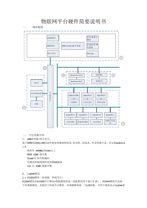
物联网平台硬件简要说明书一、硬件框图二、平台资源介绍1、 ARM处理器(网关节点)基于ARM Cortex-A8的高性能处理器架构体系,低功耗、低成本、外设资源丰富,可安装Android 4.0。
频率从 600MHz到1GHz以上NEON SIMD 指令集Thumb-2 指令集编码内置高性能的图形处理器SGX540128 位 SIMD 数据引擎2、 Zigbee模块2.1 CC2530模块(协调器、终端节点)CC2530模块由CC2530芯片模块+底板模块组成(底板模块用于接口扩展)。
CC2530模块中包括一个协调器模块,其他用于终端节点模块。
协调器模块接一个LCD面板,可用于跟踪显示Zigbee建网信息,终端节点接各种传感器。
2.2 传感器模块(1)光敏传感器(2)烟雾传感器(4)温湿度传感器(5)火焰传感器(6)气体传感器(7)热释红传感器(8) 磁通传感器3、RFID 设备模块(1) RFID模块(2) RFID标签4 、蓝牙模块(1)主蓝牙模块(2)从蓝牙模块,可接多种传感器5、CC-Dubug 仿真器,RS232CC-Dubug用于烧写或调试Zigbee 模块,RS232用于zigbee模块与上位机信息交互6、开关选择模块选择特定的zigbee模块烧写程序或与上位机串口通信三、配件方案1 ARM处理器方案一:(1)购买(2)推荐产品:友善之臂Tiny210SDK2+LCD(3)价格:799-1099,不包括配件(4)可选配件:3G上网卡,SD WIFI ,CMOS摄像头,监控摄像头模块,GPRS模块2、 Zigbee模块方案一:CC2530芯片模块管脚间隔与万能板间距一样,底板模块自己定制。
(1)购买CC2530芯片模块,万能板,其他配件(2)推荐产品:鼎泰克电子有限公司出的DRF1605(CC2530芯片模板)(3)价格:协调器模块+LCD+万能板+其他配件终端节点+底板模块传感器方案二 CC2530芯片模块+特定底板模块(1)购买(2)推荐产品:丘捷科技有限公司出品(3)价格:协调器模块+LCD+特定底板模块 260终端节点+底板模块 115传感器 25*73、RFID 设备模块(1)购买(2)推荐产品(3) 价格:1804 、蓝牙模块(1)购买(2)推荐产品大菠萝电子产品连锁商城(3)价格:主蓝牙模块 54从蓝牙模块 545、CC-Dubug 仿真器(1)价格: 586、开关选择模块7、其它接口及外设四、实验开发1 嵌入式linux开发1.1ARM处理器接口试验1.2Linux系统移植试验1.3Linux 驱动开发试验1.4Android 开发2无线通信试验2.1CC2530接口试验2.2基于CC2530传感器实验2.3Zigbee通信协议试验2.4android 下传感器界面开发2.5蓝牙模块开发2.6RFID模块开发3综合实验3.1基于android的物联网管理系统硬件环境:物联网开发平台+ PC主机软件环境:Windows、Linux 操作系统下的android环境项目功能简述:在Windows、Linux 操作系统下编写android物联网管理软件实现对物联网开发平台上传感器信息的采集和对执行单元的控制。
百度物联网平台ppt课件

更多信息,请看https:///doc/IOTDM/index.html
8
数据处理计算
9
规则引擎(Rule Engine)
规则引擎就是通过灵活的设定规则,将设备传上云端的数据,送往不同的数据目的地(如时序数据库TSDB、Kafka、 对象存储BOS等)以达到不同的业务目标。 提供以下功能: • 构建应用程序 • 并行操作 • 多方转发 • SQL规范 • 规则验证
帮助开发者能更高效地将各类设备与云端互联并利用天工物联网平台完善的接入存储计算和分析能力打造物联网应用包含了物接入的c语言客户端序列化和反序列化设备管理协议解析等功能组件涵盖了实现设备上云时在断线缓存在线检测设备管理数据安全传输等场景数据接入与管理新版物管理可以直接连接设备并且存入时序数据库物接入iothub物接入iothub是全托管的云服务通过主流的物联网协议mqtth
Disadvantage:
• 物接入使用原生MQTT需要用户有较强规划能力,不易用
Strategy: • 侧重于大数据, • 嘟米科技 • 从容维保
17
• 在云端为用户提供工业协议解析服务(比如Modbus和OPC UA)服务。 • 当云端收到网关返回的原始数据后,结合用户提供的设备通讯地址表,“物解析”将数据解析成直接可用
于存储和分析的数据。 • 设备通过IoT Edge SDK 连接到物解析 • 提供以下功能:
o 网关设备管理 o IoT Edge SDK o 设备轮询配置管理 o 协议数据解析
开发者可以基于MQTT 数据流做物联网应用开发,更加灵活,但是数据存储TSDB需要通过规则引擎。
ioThinx IIoT Starter Kit用户手册版本1.0,2019年7月,www.moxa
ioThinx IIoT Starter Kit User’s ManualVersion 1.0, July 2019/product© 2019 Moxa Inc. All rights reserved.ioThinx IIoT Starter Kit User’s Manual The software described in this manual is furnished under a license agreement and may be used only in accordancewith the terms of that agreement.Copyright Notice© 2019 Moxa Inc. All rights reserved.TrademarksThe MOXA logo is a registered trademark of Moxa Inc.All other trademarks or registered marks in this manual belong to their respective manufacturers.DisclaimerInformation in this document is subject to change without notice and does not represent a commitment on the part of Moxa.Moxa provides this document as is, without warranty of any kind, either expressed or implied, including, but not limited to, its particular purpose. Moxa reserves the right to make improvements and/or changes to this manual, or to the products and/or the programs described in this manual, at any time.Information provided in this manual is intended to be accurate and reliable. However, Moxa assumes no responsibility for its use, or for any infringements on the rights of third parties that may result from its use.This product might include unintentional technical or typographical errors. Changes are periodically made to the information herein to correct such errors, and these changes are incorporated into new editions of the publication.Technical Support Contact Information/supportMoxa AmericasToll-free: 1-888-669-2872 Tel: +1-714-528-6777 Fax: +1-714-528-6778Moxa China (Shanghai office) Toll-free: 800-820-5036Tel: +86-21-5258-9955 Fax: +86-21-5258-5505Moxa EuropeTel: +49-89-3 70 03 99-0 Fax: +49-89-3 70 03 99-99Moxa Asia-PacificTel: +886-2-8919-1230 Fax: +886-2-8919-1231Moxa IndiaTel: +91-80-4172-9088 Fax: +91-80-4132-1045Table of Contents1.Preface .............................................................................................................................................. 1-1Revision ............................................................................................................................................ 1-2 Relevant Models ................................................................................................................................. 1-2 Package Contents ............................................................................................................................... 1-2 Hardware and Software Requirements ................................................................................................... 1-2 Additional Resources ........................................................................................................................... 1-2 2.Product Overview .............................................................................................................................. 2-1ioThinx 4500 Series Specifications ........................................................................................................ 2-2 IO Board Specifications ....................................................................................................................... 2-3 Supported IO Signals ................................................................................................................... 2-4Supported Modbus Addresses ....................................................................................................... 2-5 Default Wiring Between the Device and the I/O Board ............................................................................. 2-8 Connecting to the Device’s DI Channel ........................................................................................... 2-8Connecting to Device’s DO Channel ............................................................................................. 2-10Connect to the Device’s AI Channel ............................................................................................. 2-11 3.Start with the Starter Kit ................................................................................................................... 3-1How to Get Data From Modbus ............................................................................................................. 3-2 How to Get Data From RESTful API ....................................................................................................... 3-2 How to Get Data From MQTT ................................................................................................................ 3-21PrefaceThe following topics are covered in this chapter:❒Revision❒Relevant Models❒Package Contents❒Hardware and Software Requirements❒Additional ResourcesioThinx IIoT Starter Kit PrefaceRevisionVersion Change DateV1.0 First Release 2019/6/24Relevant ModelsModel Name DescriptionioThinx 4510 Advanced I/O, Ethernet network adapter, 3-in-1 serial port(s), -20 to 60°C operatingtemperature45MR-1601 Module for the ioThinx 4500 Series, 16 DIs, 24 VDC, NPN, -20 to 60°C operatingtemperature45MR-2600 Module for the ioThinx 4500 Series, 16 DOs, 24 VDC, sink , -20 to 60°C operatingtemperature45MR-3800 Module for the ioThinx 4500 Series, 8 AIs, 0 to 20 mA/4 to 20 mA, -20 to 60°Coperating temperaturePackage ContentsThe following items are included in the product package.•ioThinx 4510, 45MR-1601, 45MR-2600, and 45MR-3800•I/O board•12 V power adapter with US/EU/UK/AU plugHardware and Software RequirementsYou will need the following hardware and software to use the ioThinx IIoT Stater Kit.• A PC running a Windows OS with Chrome installed and an Ethernet cable•IOxpress software utility (optional)•Moxa CLI Configuration Tool (optional)Additional ResourcesRefer to the following documents for additional information.•Datasheets for the following products:ioThinx 4510 SeriesioThinx 4500 Series (45MR) Modules•User’s Manual for the following products:ioThinx 4510 SeriesioThinx 4500 (45M) Module SeriesMoxa CLI Configuration Tool•Tech notes:How to Use MQTT to Connect to the ioThinx 4510 SeriesHow to Use RESTful API to Connect to the ioThinx 4510 SeriesHow to Use Modbus TCP to Connect to the ioThinx 4510 Series2Product OverviewThe following topics are covered in this chapter:❒ioThinx 4500 Series Specifications❒IO Board SpecificationsSupported IO SignalsSupported Modbus Addresses❒Default Wiring Between the Device and the I/O BoardConnecting to the Device’s DI ChannelConnecting to Device’s DO ChannelConnect to the Device’s AI ChannelioThinx 4500 Series Specifications Input/Output InterfaceDigital Input Channels:45MR-1601: 16Digital Output Channels:45MR-2600: 16Analog Input Channels:45MR-3800: 8Buttons: Reset buttonIsolation: 3k VDC or 2k VrmsDigital InputsConnector: Spring-type Euroblock terminalSensor:Dry contactWet contact (PNP)Digital OutputsConnector: Spring-type Euroblock terminalI/O Type: SinkAnalog InputsConnector: Spring-type Euroblock terminalI/O Type: CurrentInput Range:0 to 20 mA4 to 20 mA4 to 20 mA (with burn-out detection)Ethernet Interface10/100BaseT(X) Ports (RJ45 connector): 2, 1 MAC address (Ethernet bypass)Magnetic Isolation Protection: 1.5 kV (built-in)Ethernet Software FeaturesConfiguration Options: Web Console (HTTP)Industrial Protocols: Modbus TCP Server (Slave), RESTful API, SNMPv1/v2c/v3, MQTTSerial InterfaceConnector: Spring-type Euroblock terminalNo. of Ports: 2 x RS-485 (2 wire)Stop Bits: 1, 2Serial SignalsRS-485-2w: Data+, Data-, GNDSerial Software FeaturesIndustrial Protocols: Modbus RTU Client (Master)Power RequirementsInput Voltage: 12 VDCSystem Power ParametersNo. of Power Inputs: 1Power Connector: Spring-type Euroblock terminalPower Consumption: 1100 mA @ 12 VDCPhysical CharacteristicsDimensions: 400 x 170 x 116 mm (15.75 x 6.69 x 4.57 in)Weight: 2000 g (4.41 lb)Package ContentsDevice:1 x ioThinx 45101 x 45MR-16011 x 45MR-26001 x 45MR-3800Accessory: 1 x I/O boardPower Supply: 1 x power adapter with US/EU/UK/AU plug IO Board SpecificationsSupported IO SignalsThe starter kit I/O board supports DO mode, DI mode, and AO mode.DO ModeThere are two types of DO modes: DO (Sink) and Pulse Out. Connect the output channel with a source DImodule.DO mode 1 2DO (Sink) default ON OFFPulse Out OFF ONDO (Sink): In this case, the I/O board is a sink DO module and it must be used with source DI module,45MR-1601.Pulse Out: When the push button on the I/O board is pressed, the I/O board will generate a square wavewith pulse on/off width 500 ms.NOTE The pulse on/off width can be modified by changing the value in the holding register. For the Modbus address, please refer to the Starter Kit Modbus Mapping section.DI ModeThere are two types of DI modes: DI (Source) and DI (Sink). When the input channel is connected to a DOmodule, use the web console to turn on the light on the starter kit DO channel.DI mode 1 2DI (Source) default ON OFFDI (Sink) OFF ONDI (Source): In this case, the I/O board is a source DI module and it must be used with the 45MR-2600 sink DO module.DI (Sink): In this case, the I/O board is a sink DI module and it must be used with the 45MR-2601 sourceDO module.AO ModeWhen connecting the output channel with an AI module, four types of AO mode can be used: RTD, TC, Volt, and Curr. Rotate the knob to increase/decrease the output signal; the value can be checked on the webconsole.AO mode 1 2 3RTD (0 to 2 kilo-ohm) OFF OFF ONTC (0 to 0.1 V) OFF ON ONVolt (0 to 10 V) ON ON ONCurr (0 to 20 mA) default ON ON OFFRTD: In this case, the I/O board provides a 0 to 2 kilo-ohm resistance; use the 45MR-6600 RTD module.TC: In this case, the I/O board provides an analog output with voltage from 0 to 0.1 V; use the 45MR-6800 TC module.Volt: In this case, the I/O board provides an analog output with voltage from 0 to 10 V; use the 45MR-3810 AI module.Curr: In this case, the I/O board provides an analog output with current from 0 to 20 mA; use the 45MR-3800 AI module.Supported Modbus AddressesStarter Kit Modbus Mapping0xxxx Read Coils (Function 1)Reference Address Data Type Description00001 0X0000 Bit DI0 Status (0: OFF, 1:ON)00002 0X0001 Bit DI1 Status (0: OFF, 1:ON)4xxxx Read/Write Holding Registers (Function 3)Reference Address Data Type Description40001 0X0000 WORD DO0 ON Width (ms)40002 0X0001 WORD DO1 ON Width (ms)40009 0X0008 WORD DO0 OFF Width (ms)40010 0X0009 WORD DO1 OFF Width (ms)Serial Port SettingsThe configuration has been uploaded to the starter kit. The following is the default serial port setting shown in the web console.1.Port SettingsMode: RS-485 2-wireBaudrate: 115200 bpsParity: NoneData Bits: 8Stop Bits: 1Flow Control: None2.Device Settings3.Profile SettingsDefault Wiring Between the Device and the I/O BoardNOTE Because of space limitations, we use the same power supply for system and field power. For an actual application, we recommended using different power supplies to ensure that the system power and fieldpower are isolated from each other.Connecting to the Device’s DI ChannelThe blue wires connect to the 45MR-1601 source DI module.Counter Mode1.Adjust the DIP switch (DO mode) on the I/O board to pulse out.2.Change the DI to counter mode in I/O settings.NOTE After changing the settings, remember to save and restart.3.When entering the dashboard, choose the DI module, 45MR-1601.4.Click the run in operation section and the DI module will count the pulse sent from the I/O board.Connecting to Device’s DO ChannelThe yellow wires connect to the 45MR-2600 DO sink module.You can change the DO module to the 45MR-2601, which is a source DO module. When you do so,1.Adjust the dip switch (DI mode) on I/O board to DI (sink).2.Change the wire on the COM port from V+ to V-.Pulse Mode1.Change the DO to pulse mode in I/O settings.NOTE After changing the setting, remember to save and restart.2.When entering the dashboard, choose the DO module, 45MR-2600.3.Click the start in operation section and the DO module will send a pulse.Connect to the Device’s AI ChannelConnect the green wires to the 45MR-3800 AI module.3Start with the Starter KitThe following topics are covered in this chapter:❒How to Get Data From Modbus❒How to Get Data From RESTful API❒How to Get Data From MQTTioThinx IIoT Starter Kit Start with the Starter KitHow to Get Data From ModbusRefer to the tech note, How to Use Modbus to Connect to the ioThinx 4510 Series, on Moxa’s website.How to Get Data From RESTful APIRefer to the tech note, How to Use RESTful API to Connect to the ioThinx 4510 Series, on Moxa’swebsite.How to Get Data From MQTTRefer to the tech note, How to Use MQTT to Connect to the ioThinx 4510 Series, on Moxa’s website.。
Nuvoton IoT 平台设备和解决方案说明书
NuMicro®IoT Platform 2023-02-20Please Contact************************URL: https:///iot_startupCompanion App Monitor/ControlClouds /ServersCloud Ready Nuvoton Provides One-Stop IoT SolutionDevice Platform Edge DevicesRouter /GatewayGateway Platform ConnectivityDriver Ready Platform RTOS Platform OS/RTOS Supported NetworkSupported Clouds Android & iOS AppNB-IoTEthernetAzure RTOSNuvoton IoT PlatformIoT Device IoT Gateway OOB Platform AI +CloudNuvoton PlatformNuMaker-IoT-M487NuMaker-IoT-M263ANuMaker-IoT-M2354NuStamp-ACK-M031LENuMaker-LoRaD-M252NuMaker-M031BTYENuMaker-M032BTAINuMaker-IoT-MA35D1-A1NuMaker-IIoT-NUC980NuMaker-RTU-NUC980NuMaker-IoT-M487NuMaker-IIoT-NUC980NuMaker-RTU-NUC980NuMaker-IoT-M487Arm PelionAmazon Web ServiceMicrosoft AzureAlibaba CloudAllxonConnectivity* Supports Ethernet /Wi-Fi / Bluetooth / 4G & LTE / NB-IoT / LoRa * Supports MQTT /CoAP/ HTTP / TLS /AWS / Web Server Storage AI + CloudIoT Gateway OOB Platform IoT DeviceNuvoton IoT PlatformIoT Platform ApplicationPlatformNuMaker Board DetailsIoT device platformIoT General PlatformNuMaker-IoT-M487For sensor fusion and machine learning device applications. SupportsArm CMSIS-NN for neural network function.NuMaker-IoT-M263A Supports a mini PCIe connector for external modules to realize3G/4G/NB-IoT connectivity functionsIoT Security TF-M Platform NuMaker-IoT-M2354The latest IoT secure platform based on Arm® Cortex®-M23 TrustZone®technology with secure keys management, and storage protected byphysical tampering shield.Amazon ACK Platform NuStamp-ACK-M031LE Amazon approved Alexa Connect Kit (ACK) platform. Easy to implementsmart home appliances with Alexa Echo speaker ecosystem.LoRa Device Platform NuMaker-LoRaD-M252LoRa device development platform is fully compliant with LoRaWANClass A/C standard and supports 868-915MHz (EU/US) or 433-470MHz(CN) Bands.BLE PlatformNuMaker-M031BTYE Microcontroller with BLE5.0 & 2.4GHz proprietary for IoT sensor node &home appliancesNuMaker-M032BTAI Microcontroller with BLE5.0 & 2.4GHz proprietary, USB and Arduinosupport for smart devicesIoT gateway platformIoT Gateway PlatformNuMaker-IoT-MA35D1-A1NuMaker-IIoT-NUC980NuMaker-RTU-NUC980IoT Gateway Platform by LinuxBasic IoT Gateway Platform NuMaker-IoT-M487Supports multiple cloud services, such as Arm Pelion, Amazon WebService, Alibaba Cloud and Microsoft Azure IoT.OOB Platform forserverOOB Platform NuMaker-IIoT-NUC980NuMaker-RTU-NUC980with Allxon Cloud serviceBasic OOB Platform NuMaker-IoT-M487Affordable OOB platform supports complete SSL and TLS library forsecure linkCustomer Attribute CapabilitiesNon-OS RTOS LinuxCore & OS 8051/ M0/ M23/ M4 MCUNo OS, use BSP onlyM4 / M23MCURTOS with lite network stack (lwIP)ARM9/ A35MPULinux with full network stack orRTOS with lite network stackNetwork No or simple non-IP networkLower data rateEthernet(exclude M2354),Wi-Fi (UART), 4G LTE (UART), NB-IoT(UART)Lower data rateEthernet,Wi-Fi (USB/SDIO),4G LTE(USB/UART), NB-IoT(USB/UART), …Higher data rateGUI No or segmented LCD with emWin or LVGL with QT,emWin, or LVGL R&D 1 or 2 3 to5> 10Applications Simple Smart Devices Home Appliances,Smart Devices…Industrial, Smart Grid,Smart Building,Smart City, …Nuvoton PlatformsNuMaker-IoT-M487NuMaker-IoT-M263ANuMaker-IoT-M2354NuStamp-ACK-M031LENuMaker-LoRaD-M252NuMaker-M031BTYENuMaker-M032BTAINuMaker-IIoT-NUC980NuMaker-RTU-NUC980NuMaker-IoT-M487NuMaker-IoT-M2354NuMaker-IoT-MA35D1-A1NuMaker-IIoT-NUC980NuMaker-RTU-NUC980NuMaker-HMI-N9H304G LTE / NB-IoT/EthernetLinux OSCustomers Device ControlNon-OSCustomers4G LTE / NB-IoT/EthernetRTOSCustomersNuvoton IoT Platform –All-in-OneNuvoton MCURF Vendor OS Vendor Cloud VendorOS & Libraries(Mbed OS / Amazon FreeRTOS / AliOS Things /Azure RTOS / RT-Thread / Linux)RF Driver (as below)RF Module(Wi-Fi / LTE / NB-IoT / LoRa / BT)Network Stacks(TCP / UDP)Application CodeCloud Client(AWS / Alibaba / Azure /Pelion / Allxon)HardwareSoftwareI/O Drivers Network Protocols(MQTT / CoAP / HTTPS)Nuvoton MCU(M0 / M23 / M4 / ARM9)•Integrate MCU/OS/Network Protocols/RF Driver/Application Demos •Multiple HW Platform•Integrate RF Driver•MQTT/CoAP Example•Cloud Certification •Customer can focus on application development.Nuvoton IoT Platform with TF-MNuvoton MCU RF Vendor RTOS Vendor Cloud VendorMbed OS 6MbedTLS & LibrariesRF Driver (as below)RF Module(Wi-Fi / LTE / NB-IoT / LoRa)Network Stacks(TCP / UDP)Application CodeCloud ClientHardwareSoftwareI/O DriversNetwork Protocols(MQTT / CoAP / HTTPS)Nuvoton MCU(M235x series with TBSA-M hardware)P S A D e v A P I sTF-M CoreSecure Boot P S A A P I sP r o t e c t e d S t o r a g e (P S )A R o T S e r v i c e sP S A A P I sI n t e r n a l T r u s t e d S t o r a g eC r y p t oI n i t i a l A t t e s t a t i o nP l a t f o r mHALApplication Root of Trust PSA Root of TrustTrusted Firmware-MIsolation BoundaryNon-Secure AreaSecure AreaSolution for your IIoT PlatformRTOS & MCU H/W Driver& RF DriverNetwork StacksSecure ProtocolsCloud Connection SDKApplication SpecifiedStart from ZeroUsing Nuvoton PlatformWith Experience RTOS / CLOUD Time ++(Month)Development Schedule123456Using Nuvoton PlatformWithout experienceConnectivity Ecosystems SupportNuMaker Board OS / RTOSIP Connectivity *3Non-IP Connectivity *3CloudsEthernetWi-FiNB-IoT Cat-M1LTELoRa (Device)BLE 52.4GArm Pelion Amazon AWS Alibaba Cloud Microsoft Azure Allxon *5青蓮雲TinyTEENuMaker-IoT-MA35D1-A1Linux ●●●●●●●RT-Thread ●●●NuMaker-IIoT-NUC980Linux ●●●●●●●FreeRTOS ●RT-Thread ●●●NuMaker-RTU-NUC980(Chili)Linux ●●●●●●●●FreeRTOS ●RT-Thread ●●●NuMaker-IoT-M487Mbed OS ●●●●●*6●●●●Amazon FreeRTOS ●●●●AliOS Things ●●●RT-Thread ●●●●Azure RTOS ●●NuMaker-IoT-M467Mbed OS ●●●●●*6●●RT-Thread ●●●●NuMaker-IoT-M2354Mbed OS *1●●●●●●●●●RT-Thread ●●●●FreeRTOS ●●NuMaker-IoT-M263A Mbed OS●●●●●●●●NuMaker-LoRaD-M252Mbed OS /Non-OS *2●NuMaker-M031BTYE Non-OS ●NuMaker-M032BTAI Non-OS ●NuStamp-ACK-M031LENon-OS●●*4*1 Support on Mbed Studio *4 Alexa Connect Kit (ACK)*2 Non-OS ver. is NuLoRaNode.*5 Software as a Service (SaaS) *3 Refer supported components for detail.*6 Require an external LoRa moduleIoT Device Platform•Arm® Cortex®-M23 core •Runs at 64 MHz•512 KB Flash Memory •96 KB SRAM •IoT NodeNuMaker-IoT-M263AP l a t f o r m s•Arm® Cortex®-M23 core •Runs at 96 MHz•1024 KB Flash Memory •256 KB SRAM•IoT Node •TrustZone •PSA CertifiedNuMaker-IoT-M2354IoT General PlatformIoT Security TF-M Platform•Arm® Cortex®-M4 core •Runs at 192 MHz •512 KB Flash Memory •160 KB SRAM •Ethernet Gateway •Machine Learning -License plate recognition,Keyword spotting, …NuMaker-IoT-M487•Arm® Cortex®-M4 core •Runs at 200 MHz•1024 KB Flash Memory •512 KB SRAM •GatewayCharging, Energy monitor Communication, ...•Machine LearningNuMaker-IoT-M467IoT Device Platform•Arm® Cortex®-M0 core •Runs at 48 MHz•128 KB Flash Memory •16 KB SRAM •IoT Node •BQB Certified NuMaker-M031BTYEP l a t f o r m s•Arm® Cortex®-M0 core •Runs at 72 MHz•512 KB Flash Memory •96 KB SRAM•IoT Node •BQB CertifiedNuMaker-M032BTAIAmazon ACK Platform•Arm® Cortex®-M0 core •Runs at 48 MHz•128 KB Flash Memory •16 KB SRAM •Alexa Sensor Node with Amazon Alexa Connect Kit (ACK)NuStamp-ACK-M031LE•Arm® Cortex®-M23 core •Runs at 48 MHz•256 KB Flash Memory •32 KB SRAM •LoRa Node •Helium Node NuMaker-LoRaD-M252LoRa Device Platform BLE PlatformAlexa Connect Kit (ACK) –Interactive with AlexaIoT Gateway PlatformP l a t f o r m s•Dual Arm® Cortex-A35•Runs at 800 MHz•128MB DDR (up to 512MB)• 1 Gb NAND Flash •Ethernet Gateway •Wireless Gateway •Edge Computing NuMaker-IoT-MA35D1-A1•Arm® ARM926 core •Runs at 300 MHz•64 MB DDR2 in LQFP64 •256 Mb SPI NOR Flash•CAN 2.0B/RS485 to ETH •Ethernet Gateway •Gateway in small size •Remote terminal unit“Chili Board ” NuMaker-RTU-NUC980•Arm® ARM926 core •Runs at 300 MHz•64 MB DDR (up to 128MB)• 1 Gb SPI-NAND Flash •Ethernet Gateway •Wireless Gateway •Edge ComputingNuMaker-IIoT-NUC980•Arm® Cortex®-M4 core •Runs at 192 MHz •512 KB Flash Memory •160 KB SRAM•Crypto accelerators •Ethernet Gateway •Machine Learning ComputingNuMaker-IoT-M487OOB Platform for Server•Arm® ARM926 core •Runs at 300 MHz•64 MB DDR (up to 128MB)• 1 Gb SPI-NAND Flash •Support Allxon •Ethernet•Support Linux 4.4•Support RT-Thread OOBNuMaker-IIoT-NUC980•Arm® Cortex®-M4 core •Runs at 192 MHz •512 KB Flash Memory •160 KB SRAM•Crypto accelerators •Support RT-Thread OOBNuMaker-IoT-M487•Arm® ARM926 core •Runs at 300 MHz•64 MB DDR2 in LQFP64 •256 Mb SPI NOR Flash•Support Allxon•CAN Bus/RS485 to ETH •Ethernet•Support Linux 4.4•Support RT-Thread OOBNuMaker-RTU-NUC980“Chili Board”P l a t f o r m sIoT gateway is a bridge to pass raw data through the network to reach a central server for further processing.NUC980(NuMaker-IIoT-NUC980)Ethernet(UART/SPI/I 2C …)(4G LTE/WiFi …)Industrial IoT GatewayApplication Key Requirements•Bridging traditional industrial networks to Internet by secure communication through multiple network connectivity •Remote configuration and web style managementNuMaker-IIoT-NUC980 Platform Features•Hardware。
iot平台是什么意思
iot平台是什么意思b2b平台是电子商务的一种模式,是英文business-to-business的缩写,即商业对商业,或者说是企业间的电子商务,即企业与企业之间通过互联网进行产品、服务及信息的交换。
商务型⒈面向制造业或面向商业的横向b2b(英文定义:directindustry b2b,vertical b2b)垂直b2b可以分为两个方向,即上游和下游。
生产商或商业零售商可以与上游的供应商之间的形成供货关系。
⒉面向中间交易市场的b2b这种交易模式是水平b2b,它是将各个行业中相近的交易过程集中到一个场所,为企业的采购方和供应方提供了一个交易的机会。
交易型⒈卖方控制型市场战略就是所指由单一卖方创建,以期谋求众多的买者,意在创建或保持其在交易中的市场势力的市场战略。
⒉买方控制型市场战略就是由一个或多个购买者创建,意在把市场势力和价值迁移至买方的市场战略。
买方掌控型市场战略除了由一个购买者轻易创建的电子市场之外,还包括买方代理型和买方合作型两种买方掌控型市场战略。
⒊中介控制型市场战略中介掌控型市场战略就是由买卖双方之外的第三者创建,以便相匹配买卖双方的市场需求与价格的市场战略。
通过b2b电商的方式,提高传统行业的交易、流通效率,继而优化和重塑传统的行业格局。
钢铁、航运、化工、农业、石油等等这些行业,都是中国的支柱行业。
此前,这些行业长期以来与互联网绝缘,业务展开模式一成不变,无法享受到互联网带来的更便捷、更高效的优势。
垂直领域交易型b2b平台不断涌现,塑化材料b2b平台大易有塑、农产品b2b平台一亩田、煤炭领域的找煤网以及钢铁全产业链电商找钢网等,都已在各自领域全面布局。
对挑选的5个行业分别搞swot分析,确认挑选每个行业的营销策略,最后搞综合分析,在行业挑选出和营销策略上作出最恰当的挑选。
(备注:swot分别代表strength(优势)、weakness(劣势)、opportunity(机会)、threat(威胁)。
一文入门百度天工IoT平台
一文入门百度天工IoT平台产品概述为了更好的推动物联网在中国的发展,百度云正式推出了物接入服务,全面助力构建物联网社会。
IoT Hub 适用于五大业务场景:智慧能源(百度园区)智能硬件工业4.0(风电厂)智能家居车联网在各场景实现的主要功能包括:设备监控,通过接入天工平台随时监控物理设备运行情况数据存储,通过TSDB存储历史数据,支持实时查询运维报警,通过规则引擎、机器学习完成故障预测、故障报警PAAS平台,让ISV解决了设备安全连接与多种类型设备都低成本接入的难题,让其专注于SaaS级的服务,让企业人力成本更聚焦,更高效。
产品市场现状盈利模式1. 按消息收费平台有每月一百万条免费消息额度,超过的按照一定数量MQTT 消息进行收费。
2. 按数据收费平台提供1百万点/月的免费额度,超过的按照x百万点/每月进行收费。
重点应用领域暂未知,通过百度天工的开发者群了解,ISV数量已初具规模,应用场景在设备监控领域已有数个成功案例。
产品结构分析★产品技术架构天工技术架构Edge SDK:百度云面向设备端提供的SDK,可以安装在单机设备或企业网关上。
安装了SDK的设备只需要配置一个云端生成的密钥便可以完成与云端连接,实现与云端通讯配置。
Edge SDK支持SSL方式连接,保证用户数据安全。
SDK运行在客户端。
目前包含三个具体的SDK:1) modbus: modbus物解析网关。
Modbus(TCP 和RTU)协议数据的采集、上传,并且在云端进行解析和存储。
2) device-management: 新版物管理SDK。
3) bacnet: bacnet 网关。
BACNET(IP)协议数据的采集、上传,并且在云端进行存储。
例如,百度modbus网关是一个端上的程序,需要运行在用户设备的现场。
它采集用户modbus从站的数据,并且上传到百度物解析服务,然后根据解析项目配置的解析设置,进行解析。
最后入库。
他通过定义订阅MQTT主题以接受管理配置(采集策略),然后执行相关的采集任务,采集到数据后,依然通过MQTT协议上数据上传到云端。
百度物联网平台
百度物联网平台⒈引言⑴目的⑵范围⑶定义⑷参考资料⒉概述⑴物联网平台简介⑵平台架构⑶主要功能⑷支持的设备类型⒊平台注册与登录⑴注册流程⒊⑴创建账号⒊⑵完善个人信息⑵登录流程⒊⑴输入账号和密码⒊⑵安全验证⒋设备管理⑴设册⒋⑴设备类型选择⒋⑵设备信息录入⑵设备绑定⒋⑴手动绑定⒋⑵自动绑定⑶设备状态监控⒋⑴设备在线状态⒋⑵设备离线状态⑷设备控制⒋⑴远程控制⒋⑵定时控制⒌数据管理⑴数据⒌⑴设备主动上报⒌⑵应用主动请求⑵数据存储⒌⑴数据存储方式选择⒌⑵数据存储周期设置⑶数据查询与分析⒌⑴数据查询语句⒌⑵数据分析功能⒍应用开发⑴应用接入⒍⑴ API接口调用⒍⑵ SDK集成⑵应用开发指南⒍⑴设备接口文档⒍⑵数据接口文档⒎安全与隐私⑴数据传输安全⒎⑴使用HTTPS⒎⑵数据加密传输⑵用户隐私保护⒎⑴隐私政策⒎⑵用户数据权限控制⒏常见问题与解答⑴设册相关问题⑵数据与查询问题⑶应用开发问题⑷安全与隐私问题⒐附件本文档涉及附件:附件1:设册示例截图附件2:数据查询接口示例代码本文所涉及的法律名词及注释:⒈物联网:指通过互联网实现物理对象之间的相互连接与通信的网络。
⒉平台架构:指物联网平台的整体结构组成,包括前端界面、后端服务、数据存储等。
⒊设备类型:指物联网平台支持的不同种类的设备,如传感器、执行器等。
⒋数据:指设备向平台传输数据的过程。
⒌数据存储:指将设备的数据保存在平台内部存储器中。
⒍应用接入:指第三方应用通过API接口或SDK与物联网平台进行连接的过程。
⒎隐私政策:指平台保护用户个人信息的规定和措施。
- 1、下载文档前请自行甄别文档内容的完整性,平台不提供额外的编辑、内容补充、找答案等附加服务。
- 2、"仅部分预览"的文档,不可在线预览部分如存在完整性等问题,可反馈申请退款(可完整预览的文档不适用该条件!)。
- 3、如文档侵犯您的权益,请联系客服反馈,我们会尽快为您处理(人工客服工作时间:9:00-18:30)。
平台使用手册
一、研发与管理
1.创建产品
将设备接入百度IoT需首先创建产品,配置接入设备基本信息。
1.在开发者完成了注册流程后,进入开发者中心,在设备接入页面,点击【新建产品】按
钮,开始创建产品。
2.设置产品类别、产品型号、联网方式,可根据自身需要设置自定义配置信息,信息填写
完成后,点击【新建】按钮;
3.产品创建完成
产品创建完成后,您可以在新产品研发的右边区域看到您刚才创建的产品。
2.下载CA及Profile文件
设备创建成功后,可快速下载Profile和CA,参考设备端开发者手册,将其烧录至设备,联网后CA会向百度IoT云平台定时发送心跳,验证设备是否与百度IoT云平台实现了互通。
点击创建的产品,点击【下载Profile】和【下载CA】按钮,下载Profile和CA;
3.检测心跳
设备联网后,在设备接入页面,可进行检测心跳操作,自动检测设备是否已向云端上报心跳,如检测成功表明已与云端连接成功;
1.点击【心跳检测】按钮
2. 正在检测
如检测成功会弹窗提醒;
如心跳检测失败,请检查烧录过程是否有误;并可重新检测。
4.数据点设置
设备与云端的具体数据交互通过数据点进行定义
1.在产品数据点页面,选择需编辑数据点的相关产品
2.点击新建数据点进行数据点的创建
3.选择数据点类型
4.根据需要选择数据类型,编辑完数据点后,点击【确认】按钮创建成功,并可对已创建
数据点进行编辑和删除操作。
5.数据点创建完成
5.数据点测试
产品创建完数据点后,需导出为设备描述文件,之后将其与CA集成,烧入设备,实现设备与云端的数据互通。
1.在数据点设置页面,点击【数据点测试】按钮
2.使用Demo APP扫描二维码,开始数据点测试;
6.批量生产
在产品数据点创建并检测无问题后,可申请批量生产,批量生成大量Profile。
1.选择要批量生产的产品型号;
2.点击【新建批次】按钮;
3.设置批次信息,注:Profile数量最多为10000个;
4.创建完成后,点击批次,可下载Profile
7.OTA升级
1.在OTA升级页面,选择要OTA升级的产品;
2.点击上传固件,固件最大10MB,格式为zip;
3.输入固件版本号及通知方式进行固件升级规则配置。
●静默为直接对设备进行升级,无提醒,无需用户干预。
●强提醒、弱提醒和被动提醒为推送给APP端信息,可在APP中进行相应规则设置。
4.配置完成
8.数据统计
数据统计页面统计的数据类型及定义如下,可随时查看对应数据:
1)新增设备:如设备首次向云端上报心跳,即表示该设备已激活,新增设备量为在指定时
间范围内激活设备的数量。
2)设备存活:有数据上报的设备定义为存活设备,该数据上报即包含心跳数据上报也包含
通过APP连接控制设备时进行的数据上报。
3)设备活跃:在指定时间内,有非心跳数据上报的设备;
4)设备在网时间:设备的在线时间,以设备心跳统计,一次心跳代表设备在网30分钟;
5)在网时长分布:一定时间内,在网时长的分布情况;
6)固件版本分布:各个固件版本的数量占比。
不统计未激活的设备。
二、服务
1.服务列表
服务列表用于展示服务的基本信息,可在服务详情中查看服务的点击【查看文档】了解如何使用对应服务;
2.服务管理
服务管理用于查看服务的基础数据信息
三、应用
1.创建应用
设备如需通过APP控制,需先创建应用,获取应用的AK、SK等基本信息后才可进行操作
1.点击【创建应用】按钮;
2.输入应用名称,即可创建成功
2.配置应用
1.选择要配置的应用
2.可复制APP的API Key、Secret Key,选择APP所处的平台
Android需要填写包名和应用签名
iOS需要填写Bunld ID
Web需要填写授权回调地址:
3.关联产品
关联产品作用为APP授予研发产品及型号的控制权限,即:如果将某个产品型号关联在某个APP下,该APP就可以控制该型号下所有批次的设备;
可添加删除相应型号,选择成功后,点击【确认】按钮,完成关联。
四、开发文档
开发文档展示了开发时所需的常用文档信息,可点击左侧文档标题查看文档详情。
五、常见问题
常见问题按使用流程,将问题分为六大类型:设备接入、设备管理、统计分析、云平台SDK、服务与应用、账户及其他,开发者可根据问题出现的类型快速查找定位问题,并可通过搜索功能搜索问题。
六、账户
1.查看修改账户信息
1.点击账户名,查看账户基本信息;
2.点击【修改基本信息】链接即可对基本信息进行修改;
2.修改绑定手机
在账户安全信息页面,点击【修改】按钮,修改绑定手机。