
ET 200SP系统冗余功能
S7300下挂et200从站软冗余系统调试总结
一 STEP内程序设置注意问题Step中程序大体按照西门子手册设置后需要特别注意以下几点1.冗余软件版本问题,注意版本必须新的否则不能支持最新的CPU。
2.DB数据块的使用问题用户需要手动创建的数据块为:冗余数据DB块(冗余数据同步),块和IEC计数器和IEC 定时器的背景数据块;在fc100参数设置时,两个数据块的长度必须和实际使用量一直。
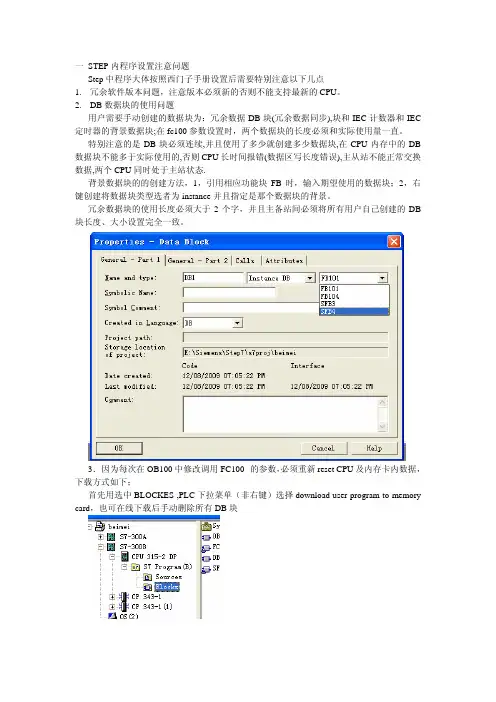
特别注意的是DB块必须连续,并且使用了多少就创建多少数据块,在CPU内存中的DB 数据块不能多于实际使用的,否则CPU长时间报错(数据区写长度错误),主从站不能正常交换数据,两个CPU同时处于主站状态.背景数据块的的创建方法,1,引用相应功能块FB时,输入期望使用的数据块;2,右键创建将数据块类型选者为instance并且指定是那个数据块的背景。
冗余数据块的使用长度必须大于2个字,并且主备站间必须将所有用户自己创建的DB 块长度、大小设置完全一致。
3.因为每次在OB100中修改调用FC100 的参数,必须重新reset CPU及内存卡内数据,下载方式如下;首先用选中BLOCKES ,PLC下拉菜单(非右键)选择download user program to memory card,也可在线下载后手动删除所有DB块其次再次选中BLOCKS后选择PLC下拉菜单DOWNLOAD或者右键DOWNLOAD注:必须进行第二次下载否则CPU及通讯模块会出错,CPU无法正常进行冗余连接。
3.OB35冗余程序组织块中的程序末尾调用FB100是CALL POSITION参数必须设置为false,并且只能在STL语言环境下才能设置参数。
4.网络组态中因为存在两个ethernet网络所以必须在建立两个CPU的ISO on TCP连接时注意该连接的正确ethernet网络。
特别注意的是连个网络的网络号必须一致,按照冗余手册上介绍的冗余时local id必须大于2,子网必须是冗余数据同步网络名,而不能是os监控网络(数据冗余网络和监控网络是同一网络除外,即数据同步和上位机通讯为同一cp)上图中名为syn的网络为数据冗余同步网络,名为OS的网络为是用来和上位机通讯的网络。
A0581_如何配置冗余系统中的ET200M从站

A0581_如何配置冗余系统中的ET200M从站在冗余系统中配置ET200M从站涉及到以下步骤:
1.确认硬件要求:冗余系统中必须使用两个ET200M从站来实现冗余,每个从站都必须有单独的电源供应,以保证系统的可靠性。
确保每个
ET200M从站都正确安装到机架上。
2.连接通信模块:将两个ET200M从站的CPU模块与通信模块进行连接。
通信模块是负责实现从站之间的数据交换和通信的关键组件。
3. 配置硬件参数:使用配置工具(如Step 7)对每个ET 200M从站
进行配置。
首先,为每个从站分配一个唯一的硬件地址,确保从站之间的
通信能够正常进行。
其次,设置每个从站的通信速率和其他硬件参数,以
保证冗余系统的性能。
4.配置软件参数:使用配置工具对每个ET200M从站进行软件配置。
根据具体的应用需求,可以配置从站的输入输出模块、通信参数等。
5.设置冗余模式:在配置工具中,选择冗余模式。
冗余模式有两种:
冷备份和热备份。
冷备份是指其中一个ET200M从站处于待机状态,并在
主站发生故障时才接管工作;热备份是指两个从站同时工作,并实时同步
数据,在主站发生故障时,备份站可以无缝接管工作。
6.运行测试:在配置完成后,进行冗余系统的测试。
包括模拟主站故障、手动切换主备站等。
确保系统在各种异常情况下都能正常工作,并保
证数据同步和通信的可靠性。
总结:配置冗余系统中的ET200M从站需要确认硬件要求,连接通信模块,配置硬件参数和软件参数,设置冗余模式,并进行测试。
这样可以确保系统的可靠性和冗余工作的正常进行。
施瓦特ET200SP电动起动器基座单元3RK1908-0AP00-0FP0的说明书

3RK1908-0AP00-0FP0 起始页 3/5
Cax 在线发生器 /WW/CAXorder/default.aspx?lang=en&mlfb=3RK1908-0AP00-0FP0
Service&Support (用户手册,操作说明书,认证证书,特性曲线,常见问题,...) https:///cs/ww/zh/ps/3RK1908-0AP00-0FP0
P24V M
L1 L2 L3 PE
P24V M AUX
上一次修改:
2019/4/18
3RK1908-0AP00-0FP0 起始页 5/5
2019/4/26
保留变更权利 © Copyright Siemens
2019/4/26
保留变更权利 © Copyright Siemens
● 用于辅助和控制电路 可连接的导线截面类型 用于负载端的输出
● 单芯线的 ● 细芯线的 无电缆末端加工 ● 细芯线的 带有电缆末端加工 可连接的导线截面类型 在 AWG 导线处 用于负载端的 输出 可连接的导线截面 在 DC 输入端 ● 单芯线或多芯线 ● 细芯线的 无电缆末端加工 ● 细芯线的 带有电缆末端加工 AWG 号码 在 DC 输入端 作为已编码可连接的导线截 面 螺丝刀头的形状 螺丝刀头的尺寸
主电路 极数 用于主电路 电压类型 工作电压 工作电压
3RK1908-0AP00-0FP0 起始页 1/5
SIMATIC 附件 基座单元 未供电,带有用于故障安全型电机起动器的 F-DI ET 200SP
西门子SIMATIC ET200SP模块说明书

yes, firmware update
Yes; green/red DIAG LED Yes; Green LED
Potential separation Potential separation channels ● between the channels ● between the channels and backplane bus ● between the channels and the power supply of the electronics
2 545 V DC/2 s (routine test) III
DC 2545 V 2 s (routine test), impulse voltage test DC 7200 V / 5 positive and 5 negative pulses (type test) 707 V DC (type test)
Dimensions Width
20 mm
Weights Weight, approx.
last modified:
56 g 09/21/2017
6ES7136-6RA00-0BF0 Page 3/3
09/29/2017
Subject to change without notice © Copyright Siemens
Data sheet
6ES7136-6RA00-0BF0
SIMATIC DP, ELECTRON. MODULE FOR ET200SP, F-RQ 1X24VDC/24..230VAC/5A ST, 20MM WIDTH, 1 RELAY OUTPUT (2 NO-CONTACTS) TOTAL OUTPUT CURRENT 5A, RATED VOLTAGE DC 24V AND AC 24 .. 230V, USEABLE UP TO PL E (ISO13849-1: 2008)/ SIL 3 (IEC61508: 2010) IF CONTROLLED BY A F-DQ (E.G. 6ES7136-6DB00-0CA0)
Siemens SIMATIC ET 200SP 8通道24V DC 数字输入模块说明书

Yes
24 V -30 to +5 V +11 to +30V
6.8 mA
Yes; 0.05 / 0.1 / 0.4 / 0.8 / 1.6 / 3.2 / 12.8 / 20 ms (in each case + delay of 30 to 500 µs, depending on line length) 0.05 ms 20 ms 0.05 ms 20 ms
Supply voltage Rated value (DC) permissible range, lower limit (DC) permissible range, upper limit (DC) Reverse polarity protection
Input current Current consumption, max.
1 000 m 600 m
Yes 2 mA
Yes
Yes
Yes Yes Yes No No No Yes
Yes; green PWR LED Yes; green LED No Yes; green/red DIAG LED
6/3/2022
Subject to change without notice © Copyright Siemens
Isolation Isolation tested with
Standards, approvals, certificates Suitable for safety functions
Ambient conditions Ambient temperature during operation ● horizontal installation, min. ● horizontal installation, max. ● vertical installation, min. ● vertical installation, max. Altitude during operation relating to sea level ● Installation altitude above sea level, max.
SIMATIC ET 200SP全新一代分布式IO
SIMATIC ET 200SP全新一代分布式I/O
您的分布式 I/O 有什么特殊需求吗?SIMATIC ET200 系统是多功能、模块化、灵活的系统,用于分布式自动化。
我们的分布式 I/O 系统可以安装在控制柜里、机器上或者爆炸危险场所。
此范围内的所有产品都可以通过 PROFIBUS 或 PROFINET 集成到您现有的自动化系统中。
下面将为您详细介绍SIMATIC ET 200SP全新一代分布式I/O。
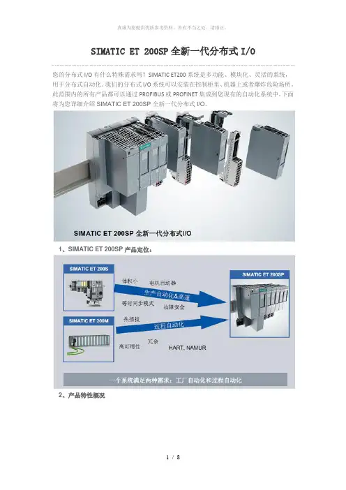
1、SIMATIC ET 200SP 产品定位:
2、产品特性概况
3、突出亮点
4、系统构成
5、IO模块,标识编码
6、底座单元
7、系统集成电源模块
8、更小的尺寸
9、与ET200S比较
10、总线适配器 - 用于PROFINET接口模块IM155-6PN
11、标签组
12、集成PROFIenergy功能
13、采用PROFINET高速通讯
14、高性能接口模块–支持系统冗余
15、SMATIC ET200SP小结。
SIMATICET200SP全新一代分布式IO
h动化]∣llll⅝⅝∣!∣∣1、SlMATlC ET 200SP 产品定位:SlMATIC ET 200SP 全新一代分布式I/O您的分布式I/O 有什么特殊需求吗? SIMATIC ET200系统是多功能、模块化、灵活的系统, 用于分布式自动化。
我们的分布式I/O 系统可以安装在控制柜里、机器上或者爆炸危险场所。
此范围内的所有产品都可以通过PROFIBUS 或 PROFINET 集成到您现有的自动化系统中。
下面将为您详细介绍 SIMATIC ET 200SP 全新一代分布式I/O 。
SlMATlC ET 200SSJMATIC Fr 200SPSIMATK ; ET 2WM高町用世HART. NAMUFt色塁小电枫启动踞SIMATlC ET 2Q0SP 全新一代分布式"02、产品特性概况产ΛB⅛⅛^⅛tt⅛≠= IF ft -)⅛Λ⅛¾ * [IAJ 1KTDrfC -}y *予,伞昌3、突出亮点简单易用-势形小巧L 功能渥大易阳—小巧—⅛x4、系统构成气煤琢阿«9HrA P RQF ⅛ι⅛ 写丫珀卍 曜谄PROFiM ∈TV2 3宅岭毎塔痒PHO S lhETifeifi (R l H3. FC. Jtfh PRoFieIJs-DPAS r .ln⅛rfac* .z∏⅛ Fj l K⅛i∏*i 0⅛«K"<⅞ft⅛∙- ss⅛rσ¾ ⅜A⅞⅞F⅛r⅛≡^flt -JL-'" Ll S f f - ■B 阿 9⅞ J标誓駅耳IR ⅛⅛⅛*片苛杠貫冇齐乍窈 kS«31 2S μ≡ C^ I t^ J⅛∣ l<WF Λ‰t⅛ t⅛ 希追宰,r⅛f÷^∣!f M⅛W±⅞**-aι⅛<jk*u⅛f⅛β4 ^lSi⅛ l∞*W ∣tT2MS⅛⅛^ W⅛⅛^⅛⅛ETMMXET 3OJS-⅛∙ 50⅝41 口*快(IMk + SefVer ff⅛ (SH)5、IO模块,标识编码i&Vr LED ⅛r*⅛n∕f∙d}iEtr⅞⅞i RUN-Mfl方⅞!M∙埃信曜進拧谀期出对横我LED■道議・LED (HF)■理世故耳PWR LEDLVL2俱电正幫打费号VLFBIrW:遵孰VdRIjiJftJb抽堤醍号文車»an—号∣9■磊代妈开关■■入■幵⅝MtUViIaX ■入■ IKfilMtiI#匪K□∣i⅛t (IMk +ServprHft(SM)6、底座单元«A£H的机■帳描自动进播的粧压总以用于电可达230 VAC/10 A自渤達椎的AUX电压誌輩用于■勖■&砥BΓ⅛ii∂ VA&iO A吃汁傅号■子可iSJO f'A∪x M-FU_ Z4⅜⅛⅜^1、匚工子盒町拆■二2 j< ■ ⅛∣⅛ ÷ ■ !C⅛⅛T :■-.- <! Q → I J- ⅛⅛⅛ ⅛ i rτ⅜M⅛ - i≤⅛'1'U⅛⅛T<⅛t7、系统集成电源模块⅛r*ft⅛ DC24V IOAlIlΛ⅛•舟由白e*SΨ⅝M・今躱怪暮霍是时麹∙lfi的扩4~>慢性反[⅛ħt护•今为Ibll压Si∣¾÷⅛^⅛i!tfiΛ5A8、更小的尺寸* ⅛⅛≡⅛X≈!Ξ?-⅛CB于接找(⅛K崔押a⅞⅛的撩况~F)・*>W⅛^B⅛⅛⅛⅛L'^r,l::沾Dimn理凱肾内9、与ET200S比较ZXRJςβuι AdaPItr> ・tt⅛⅛4的尺M亍罐头^⅛⅛5τi⅛M:・RffW ⅛⅛1⅛if ¾»IXFCA^AAafiRB• l⅛r^W⅛ 述迭Sg⅛⅛t⅛*⅛⅛n-K-X⅛810、总线适配器-用于PRoFlNET接口模块IM155-6PN11、标签组.⅛!!.⅛⅛Λ^⅛S÷ - =SaW(X 12、集成PRQFIenergy 功能XftMlPROFlantfg v⅛it⅞iΛ M Ei 定戈1'0:一霁控匚=董∙H. 5λ >于⅛⅛业克醴爼3 f-可定x⅛<jn⅛⅛x⅛tα: τr.或卷保持⅛C(i t i⅛⅛厭少自券栽At希純丐再哎听軽甲口:二・≡T*⅛⅛^^⅛S<1∕5 的⅛*⅛κ-⅛t⅛KLED∣M⅛H⅛⅛⅛⅜ 电號車A S5%3 V ff⅛ JK13、采用PRQFiNET高速通讯呵壕口∙.,^⅛⅛戰电Q兀It或岩#0权决上ST WOSPAW 性IeLt ET JflOSlM1⅞--SPN S⅛πd⅛rd-∣J⅛4^■ It ET 2009∣M1⅛^5PNh⅛h S⅛⅛ftd i⅛e^ 快遽的.尊时周歩的B≡⅝*苛枕总战伺宿W专⅛j l MMB KS-:31,25 PR⅛⅛环时同∈T ZoOS Sta伽唧S. HJ .'⅛X ;:,Jlil"itd」亠:::::歳ET 2OO⅛Hi⅞h Sp⅞βd*TΓ2003P14、高性能接口模块-支持系统冗余冗IMPHCFlHET H ∣⅛S1∣÷PF(OnNET舞韋■ (Ut拶Jt雹韵悔畿时划。
在STEP7 V5.x中如何实现ET200SP的组态控制功能
在STEP7 V5.x中如何实现ET200SP的组态控制功能ET200SP具有组态控制(Configuation control)功能。
组态控制允许使用 ET 200SP 分布式 I/O 系统的单一组态来运行各种实际组态。
即可以组态一个通用的硬件配置下载至PLC中,然后在程序中通过控制数据记录196的方式,使得下载至PLC中的单一硬件组态可以适用于多种不同的实际配置。
本文以一个例子来说明组态控制的实现过程。
在这个例子中,ET200SP站点共组态了7个插槽,具体模块类型如图1所示。
图1.ET200SP的硬件组态而实际上,真正所用到的模块如图2所示,其中第1、2插槽为DQ8 x 24VDC/0.5A HF模块,第3、4插槽为DI8 x 24VDC HF模块,第5插槽是空槽,没有安装电子模块,只安装了一个BU外壳,第6个插槽为服务器模块,第1和第3插槽启用了新的电势组。
图2.ET200SP实际站点配置要实现组态控制,首先双击ET200SP,在属性对话框的参数标签下使能ET200SP 组态控制功能,如图3所示:图3.使能组态控制然后将硬件组态编译下载至PLC中。
接下来在PLC中编程,对接口模块写数据记录196。
数据记录196的内容说明如表格1和表格2所示:表1.数据记录196内容控制元素的说明如表2所示:表2.控制元素的说明在本例中,在DB1中存储该数据记录,并按实际配置参数化该DB块,如图4所示:图4.在DB1中参数化数据记录196在OB1中,当M10.0为1时调用SFB53,写数据记录至ET200SP接口模块,数据记录传输成功后,复位M10.0,不再调用SFB53,如图5所示:图5.在OB1中编程写数据记录下载:点击下载项目例程 ( 728 KB )该项目例程由STEP7V5.5SP3HF5创建。
提示:更多关于ET200SP组态控制功能的信息,可参看ET200SP接口模块手册4.3章节,条目ID:84133942。
精细化安全控制绘图-ET 200iSP系统说明书
1 of 19Copyright 2021 by Siemens AG. All Rights ReservedA5E00455287-AE; Stand 10/2021SIEMENSIntrinsic Safety Control DrawingET 200iSP system in total"No revision to drawing without prior Approval by FM Approvals!"PLCPCThe complete interface system ET 200iSP with its components is represented in the Control Drawing.You can find the pin configuration in the manuals “Distributed I/O ET 200iSP” or "ET 200iSP Distributed I/O Device - Fail-safe Modules".Non hazardous areaPROFIBUS DPRS 485-IS CouplerHazardous areaClass I, DIV 2, GP A...D Class I, Zone 1, Group IIC T4Class II, III, GP EFGPROFIBUS RS 485-ISHazardous areaClass I, II, III, DIV 1, GP A...G Class I, Zone 0, Group IIC T4A5E00455287-AE2 of 19Copyright 2021 by Siemens AG. All Rights ReservedA5E00455287-AE; Stand 10/2021Intrinsic Safety Control Drawing A5E00455287-AEET 200iSPsystem in totalThe supply (of electrical energy) of the components is represented in the following drawing.Notes1. POWER SUPPLYThe power supply supplies the Interface Module, the I/O electronic modules and the field circuit. The power supply provides the following supplies:- Power Bus for the I/O modules and the field circuit - Electrical circuit for S-Bus- Electrical circuit for Interface ModulesThe power supply is specified in the following. 2. INTERFACE MODULESThe Interface Modules are the connector between the fieldbus and the internal Bus of the ET 200iSP with the I/O modules. The input and output data are processed.The Interface Module supplies the Electrical circuit for external field bus system. 3. I / O MODULESThere are as many as 32 I/O modules arranged in the internal bus system (taking into account a maximum supply current of 5 A total). You can find the rule to determine the maximum number of modules in the manual “Distributed I/O Station Type ET 200iSP“. Respective to the module type they enable the activation of the process interface.This applies to the complete system installed within the hazardous (classified) area. The maximum current drawn by each module is shown as I supply on the following pages.Fieldbus3 of 19Copyright 2021 by Siemens AG. All Rights ReservedA5E00455287-AE; Stand 10/2021Intrinsic Safety Control Drawing A5E00455287-AEET 200iSP system in total4. Selected intrinsically safe equipment and associated apparatus must be third party listed for theapplication, and have entity parameters conforming with Table 1 below. When installing according to FM requirements, all intrinsically safe apparatus must be FM approved .TABLE 1:I.S. Equipment Associated Apparatus V max (or Ui) ≥ Voc or Vt (or Uo) I max (or Ii) ≥ Isc or It (or Io P max, Pi ≥ PoCi + Ccable≤ Ca (or Co)Li + Lcable≤La (or Lo)5. This associated apparatus may also be connected to simple apparatus as defined in Article 504.2 andinstalled and temperature classified in accordance with Article 504.10(B) of the National Electrical Code (ANSI/NFPA 70), or other local codes, as applicable.6. Capacitance and inductance of the field wiring from the intrinsically safe equipment to the associatedapparatus shall be calculated and must be included in the system calculations as shown in Table 1. Cable capacitance, Ccable, plus intrinsically safe equipment capacitance, Ci must be less than the marked capacitance, Ca (or Co), shown on any associated apparatus used. The same applies for inductance (Lcable, Li and La or Lo, respectively). Where the cable capacitance and inductance per foot are not known, the following values shall be used: Ccable = 60 pF/ft., Lcable = 0.2 µH/ft.7. The maximum voltage U M used or generated by the equipment installed outside the hazardous areamay not exceed 250 Vac, 250 Vdc.8. Associated apparatus must be installed in an enclosure suitable for the application in accordance withthe National Electrical Code (ANSI/NFPA 70) for installation in the United States, the Canadian Electrical Code for installations in Canada, or other local codes, as applicable.9. For installation in Class II, Division 1 or 2 and Class III, Division 1 or 2 Hazardous (Classified)Locations, the system must be installed in a FM or NRTL listed dust-ignition-proof enclosure suitable for such locations.10. Intrinsically safe circuits must be wired and separated in accordance with Article 504.20 of the NationalElectrical Code (ANSI/NFPA 70) or other local codes, as applicable.11. Where multiple circuits extend from the same piece of associated apparatus, they must be installed inseparate cables or in one cable having suitable insulation. Refer to Article 504.30(B) of the National Electrical Code (ANSI/NFPA 70) and Instrument Society of America Recommended Practice ISA RP12.6 for installing intrinsically safe equipment.12. WARNING: SUBSTITUTION OF COMPONENTS MAY IMPAIR INTRINSIC SAFETY ORSUITABILITY FOR DIVISION 213. WARNING: TO PREVENT IGNITION OF FLAMMABLE OR COMBUSTIBLE ATHMOSPHERES,READ, UNDERSTAND AND ADHERE TO THE SERVICING AND MAINTENANCE PROCEDURES IN THE Manual "Distributed I/O Station Type ET 200iSP".14. Module power supply 6ES7138-7EA01-0AA0 is factory sealed. Do not open.The Distributed I/O Station Type ET 200iSP shall be installed in a FM or NRTL approved enclosure with degree of protection IP 54 in accordance with IEC 60529, per requirements of ANSI/ISA-60079-7.15. The nonincendive field wiring circuit concept allows interconnection of nonincendive field wiringapparatus with associated noninccendive field wiring apparatus, using any of the wiring methods permitted for unclassified locations.4 of 19Copyright 2021 by Siemens AG. All Rights ReservedA5E00455287-AE; Stand 10/2021ET 200iSPUse with TM-PS-A part No. 6ES7193-7DA10-0AA0 or TM-PS-B part No. 6ES7193-7DB10-0AA0 or TM-PS-A UC part No. 6ES7193-7DA20-0AA0 or TM-PS-B UC part No. 6ES7193-7DB20-0AA0.Use with TM-PS-A UC part No. 6ES7193-7DA20-0AA0 or TM-PS-B UC part No. 6ES7193-7DB20-0AA0.Power Supply 6ES7138-7EA01-0AA0Power Supply 6ES7138-7EC00-0AA05 of 19Copyright 2021 by Siemens AG. All Rights ReservedA5E00455287-AE; Stand 10/2021ET 200iSP6ES7152-1AA00-0AB0You can find the pin configuration in the manual … Distributed I/O System ET 200iSP “, chapter 11.Use with TM-IM/IM P/N 6ES7193-7AB00-0AA0 or TM-IM/EM P/N 6ES7193-7AA*0-0AA0.The following parameters for the PROFIBUS RS 485 – IS fieldbus connection apply to the interface module:FieldbusU o , V oc [ V dc ] 3.9 I sc , I o [ mA ] 136 P o , [ mW ] 132 U i , V max [ V dc ] 4.2 (*) I i , I max , P i [ A ] 4.8 P i [ W ]5Interface module IM 152 6ES7152-1AA00-0AB0Non hazardous areaRS 485-IS CouplerHazardous areaI supply = 30mAClass I, DIV 2, GP A ... D Class I, Zone 1, Group IIC T4 Class II, III, GP EFGInterface module IM 1526 of 19Copyright 2021 by Siemens AG. All Rights ReservedA5E00455287-AE; Stand 10/2021ET 200iSP6ES7152-1AA00-0AB0The following merits apply to the fieldbus line:Must be in accordance with NEC 504.30B:• L‘ / R‘ ≤ 22 µH / Ω (loopresistance) • C‘≤250 nF / km• Litz wire diameter ≤ 0.2 mm• Concentrated inductance and capacitance are not allowed in the running of the external RS 485 fieldbus system.•In applications where concentrated inductance and capacitance are considered the following values apply: C o , C a < 100 μF (A, B/IIC) or < 1000 μF (C, D/IIB) and L o , L a < 3mH (A, B/IIC) or < 15 mH (C, D/IIB)Isolating RS-485 (Generator)P o = 132 mWI 0= 136 mAET-200iSP IM152 RS-485I 0 = 93 mA7 of 19Copyright 2021 by Siemens AG. All Rights ReservedA5E00455287-AE; Stand 10/2021ET 200iSP6ES7131-7RF00-0AB0 6ES7138-7FN00-0AB0You can find the pin configuration in the manuals:“Distributed I/O ET 200iSP”, chapter 12.1 for 8 DI Namur."ET 200iSP Distributed I/O Device - Fail-safe Modules", chapter 7.1 for 8 F-DI Ex NAMUR Also see notes under “system in total”.Use with TM-IM/EM P/N 6ES7193-7AA*0-0AA0 or TM-EM/EM P/N 6ES7193-7CA*0-0AA0. The following parameters for the input circuits are applicable for the electronic module 6ES7131-7RF00-0AB0:1 input2 inputs //4 inputs //8 inputs //U o , V oc [ V dc ] 9.6 9.6 9.6 9.6 I o , I sc [ mA ]16 32 52 92 P o [ mW ]3876124 220A,B/IIC C-G/IIB A,B/IIC C-G/IIB A,B/IICC-G/IIB A,B/IIC C-G/IIB C o , C a [ µF ] 3.6 28 3.6 28 3.6 28 3.6 28 L o , L a [ mH ]110400301101245313Digital electronic module 8 DI NAMUR 6ES7131-7RF00 -0AB0Class II, III, GP EFGIntrinsic Safety Control Drawing A5E00455287-AE8 of 19Copyright 2021 by Siemens AG. All Rights ReservedA5E00455287-AE; Stand 10/2021ET 200iSP6ES7131-7RF00-0AB0 6ES7138-7FN00-0AB0The following parameters for the input circuits are applicable for the electronic module 6ES7138-7FN00-0AB0:1 input2 inputs //4 inputs //8 inputs //U o , V oc [ V dc ] 8.8 8.8 8.8 8.8 I o , I sc [ mA ] 8.81 17.62 35.24 70.48 P o [ mW ]19.438.877.6155.2A,B/IIC C-G/IIB A,B/IIC C-G/IIB A,B/IICC-G/IIB A,B/IIC C-G/IIB C o , C a [ µF ] 5.37 45.87 5.24 45.74 4.98 45.48 4.46 44.96 L o , L a [ mH ]4581000114440281147279 of 19Copyright 2021 by Siemens AG. All Rights ReservedA5E00455287-AE; Stand 10/2021ET 200iSP6ES7132-7RD**-0AB0 6ES7132-7GD**-0AB0 6ES7138-7FD00-0AB0Digital electronic module 4 DO DC23,1V/20mA 6ES7132-7RD00-0AB0 Digital electronic module 4 DO DC17,4V/27mA 6ES7132-7RD10-0AB0 Digital electronic module 4 DO DC17,4V/40mA 6ES7132-7RD20-0AB0Digital electronic module 4 DO DC 23,1V/20mA SHUT DOWN …H“ 6ES7132-7RD01-0AB0 Digital electronic module 4 DO DC 17,4V/27mA SHUT DOWN …H“ 6ES7132-7RD11-0AB0 Digital electronic module 4 DO DC 17,4V/40mA SHUT DOWN …H“ 6ES7132-7RD21-0AB0 Digital electronic module 4 DO DC 17,4V/40mA SHUT DOWN …H“ 6ES7132-7RD22-0AB0 Digital electronic module 4 DO DC 23,1V/20mA SHUT DOWN …L“ 6ES7132-7GD00-0AB0 Digital electronic module 4 DO DC 17,4V/27mA SHUT DOWN …L“ 6ES7132-7GD10-0AB0 Digital electronic module 4 DO DC 17,4V/40mA SHUT DOWN …L“ 6ES7132-7GD20-0AB0 Digital electronic module 4 DO DC 17,4V/40mA SHUT DOWN …L“ 6ES7132-7GD21-0AB0 Digital electronic module 4 DO DC 25,5V/22mA SHUT DOWN …L“ 6ES7132-7GD30-0AB0 Digital electronic module 4F DO Ex 17,4V/40mA 6ES7138-7FD00-0AB0...7RD00..., …7RD01…, …7GD00… …7RD10.., …7RD11…, …7GD10… I supply = 290 mA I supply = 260 mA …7RD20.., …7RD21…, …7GD20… I supply = 380 mA …7RD22.., …7GD21…, …7GD30… I supply = 380 mA6ES7138-7FD00-0AB0 I supply = 380 mA Hazardous area Class I, DIV 2, GP A...D Class I, ZN 1, IIC T4 Class II, III GP EFGHazardous areaClass I, II, III, DIV 1, GP A...G Class I, ZN0, IIC T4RelayYou can find the pin configuration in the manuals: “Distributed I/O ET 200iSP”, chapter 12.2 for 4 DO,"ET 200iSP Distributed I/O Device - Fail-safe Modules", chapter 7.2 for 4 F-DO Ex 17.4V/40mA Also see notes under “system in total”.Use with TM-IM/EM P/N 6ES7193-7AA*0-0AA0 or TM-EM/EM P/N 6ES7193-7CA*0-0AA0.10 of 19Copyright 2021 by Siemens AG. All Rights ReservedA5E00455287-AE; Stand 10/2021ET 200iSP6ES7132-7RD**-0AB0 6ES7132-7GD**-0AB0The following parameters for the output circuits are applicable for the electronic module 6ES7132-7RD00-0AB0, 6ES7132-7RD01-0AB0, 6ES7132-7GD00-0AB0:1 outputU o , V oc [ V dc ] 25.6 I o , I sc [ mA ]96 P o [ mW ]610A,B/IICC-G/IIB C o , C a [ nF ] 98 790 L o , L a [ mH ]313The following parameters for the output circuits are applicable for the electronic modules 6ES7132-7RD10-0AB0 and 6ES7132-7RD20-0AB0, 6ES7132-7RD11-0AB0 and 6ES7132-7RD21-0AB0, 6ES7132-7GD10-0AB0 and 6ES7132-7GD20-0AB0:1 output2 outputs //U o , V oc [ V dc ] 19.4 19.4 I o , I sc [ mA ]132 264 P o [ mW ]6401280A,B/IICC-G/IIB A,B/IIC C-G/IIB C o , C a [ nF ] 230 1500 230 1500 L o , L a [ mH ]1.980.352The following parameters for the output circuits are applicable for the electronic module 6ES7132-7RD22-0AB0 and 6ES7132-7GD21-0AB0:1 output2 outputs //U o , V oc [ V dc ] 19.4 19.4 I o , I sc [ mA ]118 236 P o [ mW ]5721144A,B/IICC-G/IIB A,B/IIC C-G/IIB C o , C a [ nF ] 240 1500 230 1500 L o , L a [ mH ]2.5110.62.711 of 19Copyright 2021 by Siemens AG. All Rights ReservedA5E00455287-AE; Stand 10/2021ET 200iSP6ES7132-7RD**-0AB0 6ES7132-7GD**-0AB0 6ES7138-7FD00-0AB0The following parameters for the output circuits are applicable for the electronic module 6ES7132-7GD30-0AB0:1 outputUo, Voc [ Vdc ] 27.9 Io, Isc [ mA ] 110 Po [ mW ] 760 A,B/IIC C-G/IIB Co, Ca [ nF ] 81 651 Lo, La [ mH ] 3 13The following parameters for the output circuits are applicable for the electronic module 6ES7138-7FD00-0AB0:1 output2 outputs //Uo, Voc [ Vdc ] 18.5 18.5 Io, Ioc [ mA ] 112.2 224.4 Po [ mW ] 5191040A,B/IIC C-G/IIB A,B/IIC C-G/IIB Co, Ca [ nF ] 267 1650 254 1640 Lo, La [ mH ]2.8 11.3 0.7 2.812 of 19Copyright 2021 by Siemens AG. All Rights ReservedA5E00455287-AE; Stand 10/2021ET 200iSP6ES7132-7RD** -0AB0 6ES7132-7GD** -0AB0The following parameters for the input circuits are applicable for the electronic modules 6ES7132-7RD*0-0AB0:The following parameters for the input circuits are applicable for the electronic modules 6ES7132-7RD*1-0AB0, 6ES7132-7RD22-0AB0 and 6ES7132-7GD**-0AB0:1 input U i , V max [ V dc ] 28 I i , I max [ mA ] 7.1P i [ mW ] 50Lineare KennlinieCi [nF ] 36.3 Li [mH ]13 of 19Copyright 2021 by Siemens AG. All Rights ReservedA5E00455287-AE; Stand 10/2021ET 200iSP6ES7134-7TD00-0AB0 6ES7138-7FA00-0AB0You can find the pin configuration in the manuals:“Distributed I/O ET 200iSP”, chapter 13.2 for 4 AI I 2WIRE HART,"ET 200iSP Distributed I/O Device - Fail-safe Modules", chapter 8.1 for 4 F-AI Ex HART. Also see notes under “system in total”.Use with TM-IM/EM P/N 6ES7193-7AA*0-0AA0 or TM-EM/EM P/N 6ES7193-7CA*0-0AA0. The connection of Ex ic field devices is only permitted if the module is installed in zone 2 or in the safe area.Analog electronic module 4 AI I 2Wire HART 6ES7134-7TD00-0AB0 Analog electronic module 4F AI EX HART 6ES7138-7FA00-0AB06ES7134-7TD00-0AB0: I supply = 280 mA 6ES7138-7FA00-0AB0: I supply = 280 mA Hazardous areaClass I, Zone 1, Group IIC T4Hazardous areaClass I, II, III, DIV 1, GP A...G Class I, Zone 0, Group IIC T4mA2-wire transducerHART field devices14 of 19Copyright 2021 by Siemens AG. All Rights ReservedA5E00455287-AE; Stand 10/2021ET 200iSP6ES7134-7TD00-0AB0 6ES7138-7FA00-0AB0The following parameters for the input circuits are applicable for the electronic module 6ES7134-7TD00-0AB0:1 inputU o , V oc [ V dc ] 27.6 I o , I sc [ mA ]88.2 P o [ mW ]610A,B/IICC-G/IIB AEx ic IIC C o , C a [ nF ] 83 665 282 L o , L a [ mH ]315.74.9The following parameters for the input circuits are applicable for the electronic module 6ES7138-7FA00-0AB0:1 input Uo, Voc [ Vdc ] 27.7 Io, Ioc [ mA ] 98 Po [ mW ]679A,B/IIC C-G/IIBAEx ic IIC Co, Ca [ nF ] 71.3 649 267.3 Lo, La [ mH ]314315 of 19Copyright 2021 by Siemens AG. All Rights ReservedA5E00455287-AE; Stand 10/2021ET 200iSP6ES7134-7TD50-0AB0You can find the pin configuration in the manual …Distributed I/O System Type ET 200iSP“, chapter 13.3. Also see notes under …system in total“.Use with TM-IM/EM P/N 6ES7193-7AA*0-0AA0 or TM-EM/EM P/N 6ES7193-7CA*0-0AA0. The following parameters for the input circuits are applicable for the electronic modules:1 input U i , V max [ V dc ] 30 I i , I max [ mA ] 150 P i [ W ] 1.2 C i [nF ] 0 Li [mH ] 0 V o , V o [ V dc ] 0.9 I o , I se [ mA ] 0.8 P o [ mW ] 0.2 C o , C a [nF ] 1000 L o , L a [mH ]1000I supply = 27 mAmA4-wire transducer16 of 19Copyright 2021 by Siemens AG. All Rights ReservedA5E00455287-AE; Stand 10/2021ET 200iSP6ES7134-7SD50-0AB0 6ES7134-7SD51-0AB0You can find the pin configuration in the manual …Distributed I/O System Type ET 200iSP“, chapter 13.4. Also see notes under …system in total“.Use with TM-IM/EM P/N 6ES7193-7AA*0-0AA0 or TM-EM/EM P/N 6ES7193-7CA*0-0AA0. The following parameters for the input circuits are applicable for the electronic module:4 inputs //U o , V oc [ V dc ] 5.9 I o , I sc [ mA ]24 P o [ mW ]36A,B/IICC-G/IIB C o , C a [ µF ] 43 1000 L o , L a [ mH ]50200Analog electronic module 4 AI RTD 6ES7134-7SD50-0AB0I supply = 19 mAHazardous areaClass I, Zone 1, Group IIC T4Class II, III, GP EFGHazardous areaClass I, II, III, DIV 1, GP A...G Class I, Zone 0, Group IIC T4Resistance thermometers17 of 19Copyright 2021 by Siemens AG. All Rights ReservedA5E00455287-AE; Stand 10/2021ET 200iSP6ES7134-7SD00-0AB0You can find the pin configuration in the manual …Distributed I/O System Type ET 200iSP“, chapter 13.5. Also see notes under …system in total“.Use with TM-IM/EM P/N 6ES7193-7AA*0-0AA0 or TM-EM/EM P/N 6ES7193-7CA*0-0AA0. The following parameters for the input circuits are applicable for the electronic module:4 inputs //U o , V oc [ V dc ] 5.9 I o , I sc [ mA ]15 P o [ mW ]23A,B/IICC-G/IIB C o , C a [ µF ] 43 1000 L o , L a [ mH ]100500Analog electronic module 4 AI TC 6ES7134-7SD00-0AB0I supply = 17 mAHazardous areaClass I, Zone 1, Group IIC T4Class II, III, GP EFGHazardous areaClass I, II, III, DIV 1, GP A...G Class I, Zone 0, Group IIC T4Thermocouplers18 of 19Copyright 2021 by Siemens AG. All Rights ReservedA5E00455287-AE; Stand 10/2021ET 200iSP6ES7135-7TD00-0AB0You can find the pin configuration in the manual “Distributed I/O System Type ET 200iSP”, chapter 13.6. Also see notes under “system in total”.Use with TM-IM/EM P/N 6ES7193-7AA*0-0AA0 or TM-EM/EM P/N 6ES7193-7CA*0-0AA0. The connection of Ex ic field devices is only permitted if the module is installed in zone 2 or in the safe area.The following parameters for the output circuits are applicable for the electronic module:outputU o , V oc [ V dc ] 27.6 I o , I sc [ mA ]88.2 P o [ mW ]610A,B/IICC-G/IIB AEx ic IIC C o , C a [ nF ] 83 665 282 L o , L a [ mH ]315.74.9Analog electronic module 4 AO I HART 6ES7135-7TD00-0AB0I supply = 330 mAHazardous areaClass I, Zone 1, Group IIC T4Class II, III, GP EFGHazardous areaClass I, II, III, DIV 1, GP A...G Class I, Zone 0, Group IIC T4HART field19 of 19Copyright 2021 by Siemens AG. All Rights ReservedA5E00455287-AE; Stand 10/2021ET 200iSP6ES7138-7BB00-0AB0You can find the pin configuration in the manual “Distributed I/O ET 200iSP”, chapter 14.2 for Watchdog module. Also see notes under “system in total”.Use with TM-IM/EM P/N 6ES7193-7AA*0-0AA0 or TM-EM/EM P/N 6ES7193-7CA*0-0AA0. The following parameters for the output circuits are applicable for the electronic module:outputU o , V oc [ V dc ] 12.7 I o , I sc [ mA ]329P o [ mW ] 910A,B,C,D/IICC,D/IIBC o , C a [ µF ] 2.3 5 L o , L a [ mH ]0.83.1WATCHDOG-Modul 6ES7138-7BB00-0AB0I supply max. = 32 mAHazardous areaClass I, DIV 2, GP A...D Class I, ZN 1, IIC T4 Class II, III GP EFGto input of electronic modules 6ES7132-7RD*1-0AB0 and 6ES7132-7GD*0-0AB0。
如何配置冗余系统中的ET-200M从站
如何配置冗余系统中的ET 200M从站1. 简介在S7-400H冗余系统中,通常配置冗余连接的ET 200M(双向I/O)。
此时,需要配置两个IM 153-2接口模块、I/O模块、用于热插拔的总线模块BM(即有源底板,包括用于接口模块的总线模块和用于I/O模块的总线模块)、DIN深槽导轨等。
配置用于冗余连接的ET 200M时,下面的组件是必需的:(1) [1] IM 153-2高性能接口模块(PROFIBUS DP Link)2块(2) [1] IM/IM总线模块(有源底板),用于安装/连接2个IM 153-2高性能接口模块(3) I/O模块,按需配置,每个ET 200M从站最多可配置12个I/O模块(4) I/O总线模块,分为两种:BM 2×40用于安装/连接2个40mm宽的I/O模块;BM 1×80用于安装/连接1个80mm宽的I/O模块(5) 用于热插拔的DIN深槽导轨注[1]:可订购IM 153冗余套件,包含2个IM 153-2接口模块和1个IM/IM总线模块。
下面的组件是可选的:(1) PS 307或PS 305电源模块本文的配置说明中,不包含PROFIBUS DP接头(连接器)、PROFIBUS DP电缆及剥线工具、I/O模块前连接器、MTA预组装电缆、空槽保护盖板、占位模块、隔离模块、集中供电电源以及其他用于硬件安装或连接部件。
2. 订货数据配置冗余连接的ET 200M,必选组件相关的订货数据可以参考下表:IM/IM有源总线模块(有源底板)订货号6ES7195-7HD10-0XA0配置个数 1个/ET 200M站配置说明每个IM/IM有源总线模块上,安装两个IM153-2接口模块,用于冗余连接。
用于IM 153-2接口模块的总线模块不能与用于I/O模块的总线模块通用。
IM 153-2高性能接口模块(DP Link)订货号6ES7 153-2BA02-0XB0配置个数2个/ET 200M站配置说明冗余配置中,每个ET 200M从站需要两个IM 153-2接口模块,分别用来连接冗余的DP主站。