明澈操作说明 MING-CHE _ User manual _CN V0.2
明锐达白板软件说明书
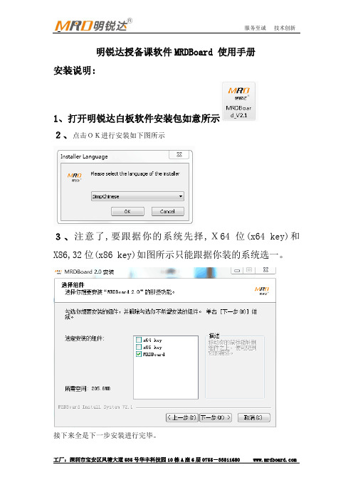
明锐达授备课软件MRDBoard 使用手册安装说明:1、打开明锐达白板软件安装包如意所示2、点击OK进行安装如下图所示3、注意了,要跟据你的系统先择,X64位(x64 key)和X86,32位(x86 key)如图所示只能跟据你装的系统选一。
接下来全是下一步安装进行完毕。
4、安装完毕后桌面上会出现这个图标为明锐达光学白板定位软件,点击进入如下图所示:设置里可以选择几点定位。
5、安装完毕后桌面上会出现这个图标,本图标为明锐达白板两边各22个快捷的服务器,会自动运行。
出厂我们以设定好,只需安装以上软件不需要设置处理能方便。
软件概述:MRDBOARD软件是一款针对课堂备课和教学开发的应用软件。
它具有界面简洁,操作简单,书写流畅等特点;可以同步展示声音,视频,flash课件,网络资源;并提供ppt标注工具和透明页标注工具方便配合原有的ppt课件教学和配合其他软件教学。
老师可在备课上课环节使用该软件可以让教学变得生动有趣,提高学习兴趣,提升教学品质。
软件工作模式:MRDBOARD软件提供编辑、全屏两种模式。
编辑模式为备课提供方便,全屏模式为上课提供方便,用户在使用过程中可以根据需要,快速切换。
编辑模式:1、编辑模式可以根据用户的喜好,隐藏或者显示菜单栏、工具栏、资源库,在工具栏上面右键弹出菜单,可设置各个部件的显示或者隐藏。
2、也可以随意调节工具栏、资源库的位置和顺序。
拖动工具栏左边区域拖动各个工具栏改变工具栏的位置,也可以拖动资源库的标题栏,移动资源库到相应的位置,下图是重新设置后的效果,用户可以根据自己的爱好随意设置界面。
全屏模式:窗口模式切换:1、编辑模式切换到全屏模式,点击工具栏中全屏模式按钮。
右上角的小衣服可以选择多项色调2、全屏模式切换到编辑模式,点击浮动工具栏右侧的编辑模式按钮。
3、全屏模式切换到电脑桌面,点击浮动工具栏左侧图标,即可切换到电脑桌面。
软件特色功能介绍:1、换肤,软件提供了六种颜色的背景的皮肤,以适应不同用户的喜好灰白界面:淡蓝界面:粉红界面:橙色界面:淡绿界面:2、透明页标注工具:3、 Ppt 标注工具:ppt 标注工具是为了配合ppt 课件教学而开发的,主要用于配合老师用ppt 进行教学。
汽车配件管理软件操作手册

汽车配件管理软件操作手册汽车配件管理软件操作手册江苏省电信有限公司索引1 登陆平台 .。
..。
...。
.。
.。
.。
.。
..。
.。
..。
....。
..。
..。
..。
.。
.......。
.。
.。
..。
.。
.。
..。
.。
.。
.。
.。
..。
..。
.。
.。
.。
.。
.。
.。
..。
.。
.。
.。
5 2 ASUPERCRM包含的业务范围。
..。
.。
.。
.。
....。
...。
...。
.。
.。
.。
.。
.。
.。
.....。
.。
....。
.。
.。
.....。
7 3 主页面 ......。
.。
..。
..。
..。
.。
..。
..。
..。
.。
..。
.。
.。
..。
.。
.。
..。
..。
.。
.。
.。
.。
.。
.。
.。
.。
.。
..。
.。
.....。
.。
.。
.。
.。
...。
.。
.。
.。
9 3。
1 业务流程图。
.。
.。
..。
..。
.。
.。
.。
.。
.。
..。
...。
.。
.。
.。
...。
.。
.。
.。
.。
.。
.。
.。
...。
.。
.。
.。
..。
....。
.. 9 3.2 快捷新建功能。
..。
.。
.。
.。
..。
...。
..。
.。
.。
.。
.。
..。
..。
.。
.。
..。
.。
.。
.。
..。
.。
..。
.。
...。
.。
....。
9 3。
3 全局搜索功能。
..。
.。
.。
..。
.。
.。
.。
.。
..。
.。
.....。
.。
.。
....。
..。
.。
..。
.。
.。
..。
.。
....。
...。
.。
..。
.。
...。
.。
.。
. 9 3。
4 配置主页 .。
.。
.。
.。
.。
...。
..。
...。
.。
.。
.。
..。
.。
.。
.。
....。
.。
...。
..。
.。
.。
..。
.。
..。
.。
..。
..。
.。
..。
.。
.。
..。
9 4 基本操作 .。
..。
.。
.。
..。
.。
.。
...。
.。
..。
.。
..。
.。
..。
.。
.。
..。
....。
...。
...。
.。
..。
.。
.。
....。
..。
....。
.。
.....。
..。
.。
....。
.。
.。
.。
. 11 4。
1 系统工具菜单 .。
.。
..。
光毓机电 RMD-X8 V1.0 用户操作手册说明书

V1.0 RMD-X User Manual For Motion ActuatorC ATALOGUE1 PRODUCT INTRODUCTION (3)1.1N AMING R ULES (3)1.2F EATURES (3)1.2.1Control Mode (3)1.2.2Communication Control Mode (3)1.2.3Encoder Feedback (4)1.2.4Technical Highlights (4)1.2.5 IP Level (4)2 INSTALLATION AND PRECAUTIONS (4)2.1I NSTALLATION D IMENSIONS (4)2.2E NVIRONMENTAL C ONDITIONS (6)3 ELECTRICAL PARAMETERS (8)3.1D ETAILED P ARAMETERS (8)V1.0 3.3H ARDWARE C ONNECTION (9)3.3.1 Interface Specification (9)3.3.2 Interface Debugging (10)3.3.3 Can Interface 1 (10)3.3.4 Can Interface 2 (10)3.3.5 Power Interface (11)3.4M ULTILEVEL C ONNECTION L INE (11)3.5D IAL C ODE S WITCH S ETTINGS (11)3.5.1 Can Bus Device Address Settings(Dial Code Switch 1-3 Bits) (11)3.5.2 Bus Terminal Resistance Setting(4th Dial Code Switch) (12)4 RMD-L CONFIGINSTALLATION AND PARAMETER SETTING (13)4.1RMD-L CONFIG B RIEF I NTRODUCTION (13)4.1.1 RMD-L config Installation (13)4.1.2 Connection Tools and Driver Installation (13)4.2H ARDWARE C ONNECTION (14)4.3P ARAMETER S ETTING (15)4.3.1 Software Connection (15)4.3.2 Basis Setting (15)4.3.3 Encoder Setting (17)4.4P RODUCT I NFORMATION (18)4.5TEST F UNCTION (19)5. COMMUNICATION PROTOCOL (21)5.1C OMMUNICATION P ROTOCOL (21)5.2RS485C OMMUNICATION P ROTOCOL (21)V1.0 1 Product IntroductionRMD-X8 motion actuator is a highly integrated power output modul e. Integrated with three major functional components of high performance FOC driver, high power d ensity brushl ess motor and high precision lightweight reducer. Break through the traditional distributed d esign, make the structure of the terminal product d esign more concise, product internal wiring more convenient, the performance of the whol e machine more stabl e.1.1 Naming Rules1.2 FeaturesProgrammable, integrated servo motor.Operating dc voltage 12-48v.1.2.1 Control ModeTorque ModeSpeed ModePosition Mode1.2.2 Communication Control ModeRS485 Communication Mode ControlCAN Communication Mode ControlV1.01.2.3 Encoder Feedback14-bit Magnetic encoder(Absolute Value)18-bit Magnetic encoder(Absolute Value)1.2.4 Technical HighlightsA. Servo control,B. High positioning accuracy,C. High speed and high response,D. Energy saving and high efficient,E. Multi-control mode,F. Smooth and low noise,G. Compact structure.1.2.5 IP LevelIP542 Installation and Precautions2.1 Installation DimensionsV1.0 AttentionThe motor input/output interface needs to keep the connection space, > 20mm is recommended.The length of mounting screws shall meet the requirements of the drawings. If too long it will damage the internal structure. If too short may become loose.Due to integrated reducer internal, the lubricating grease of the specified model 5-6ml needs to be refilled every 1000H.Axial load cannot be greater than 300N, radial load cannot be greater than 1000N.Warning:Please carefully read and follow the requirements in this manual, which will help you set up and operate the drive correctly and achieve optimal drive performance.Please install the equipment in a dry position, and should be non-flammable surroundingsPlease put in the place without grinding fluid, oil mist, iron powder, chip, etc.Please put in well ventilated, dry and dust-free place.Please put in non-vibration place.Do not use gasoline, diluents, alcohol, acid and alkaline detergents to avoid discoloration or breakage.Requirements for the use of motion actuators:Please ensure that this document is used by design engineers, installers, and those man responsible for debugging the product.Be sure to comply with the requirements of this document, as well as documentation for other components and modules.Please consider the legal requirements applicable to the place of using, including —Regulations and standards—Test organization and insurance company regulations—National specificationV1.0 Transport and storage conditionsPlease ensure that products are not subject to more than permitted burdens during transportation and storage, including—Mechanical load—Unacceptable temperature—Moisture—Corrosive gasPlease use the original packing for storage and transportation. The original packing provides enough protection to avoid regular problems.Technical requirementsGeneral conditions for correct and safe use of products must be complied with:The technical requirements for the connection and environment conditions specified in the product technical data and for all other connected components. Only if the product meets the requirements of motor specification, it is allowed to operate the product in accordance with the relevant safety procedures.Please follow the instructions and warnings in this document.Operator requirementsThis product can only be operated by engineers who are familiar with the following rules:—Familiar with installation and operation of electrical control system.—Familiar with applicable provisions for operational safety engineering systems.—Familiar with applicable provisions for accident protection and occupational safety.—Familiar with product document on provisions.2.2 Environmental ConditionsEnvironment temperature -20℃~50 ℃(Not freeze).Environmental humidity5~95%RH (Without condensation).Storage temperature 10 ℃~70 ℃(Not freeze).Storage humidity 5~95%RH(Without condensation).Installation requirements no insolation, corrosive gas and fuel dust.Altitude below 1000m.The vibration is 10 ~ 60Hz below 5.9 m/s 2.V1.0 AttentionMotor fixing screws must be locked;Cables must not be overstretched;Motor shaft and equipment shaft must be installed in good alignment;Avoid any foreign bodies entering the servo drive. Conductive or combustible foreign bodies such as screws and metal chips entering the servo drive may cause fire and electric shock.V1.0 3 Electrical Parameters3.1 Detailed ParametersV1.0 3.2 Working Range3.3 Hardware Connection3.3.1 Interface SpecificationDebugging interface:Connector type 51146-1.25mm-2p (Brand:molex)Level range:0-3.3vCan interface:Connector type SM02-GHS-TB (Brand:JST)Level range:0-5vPower interface:Connector type XT30-U (Brand:艾迈斯)V1.03.3.2 Interface Debugging3.3.3 Can interface 13.3.4 Can interface 2Note:The CAN1 interface and CAN2 interface are connected in parallel and have the sameV1.03.3.5 Power interface*Pay attention to the power supply voltage range and power supply output.*Pay attention to the anode and cathode of the power supply.3.4 Multil evel connection line3.5 Dial code switch Settings3.5.1 Can bus device address Settings(Dial code switch1st-3rd )V1.03.5.2 Bus terminal resistance setting(Dial code switch 4th)*Dial code switch 4th ON mean bus terminal resistance (120 Ω) get through;*In general, devices in the last stage of the can bus need terminal resistance(Dial code switch 4th turns On)V1.04 RMD-L config Installation And Parameter Setting4.1 RMD-L config Brief IntroductionRMD-L config is a PC debugging tool software developed by GYEMS, which can be used on computers above win7. The operation interface is as follows:4.1.1 RMD-L config InstallationRMD-L config installation is the same as the Windows universal application, justdouble-click the icon and choose the default installation path. RMD-L config Installation file download address:/support/download4.1.2 Connection Tools and Driver InstallationRMD-X8 is designed with a debugging interface (UART port), which usually requires a USB to UART tool (as shown in the figure below) to connect. The driver of this tool is installedV1.0 before use.Driver download address:/support/downloadAfter the download is complete, unzip it and double-click to start the installation until it is complete. Then insert the USB data cable, you can see whether the installation is successful in the Windows device manager. The corresponding COM port can be found in the figure below, indicating the installation is successful.4.2 Hardware ConnectionPower supply voltage adjust to 48v (the power supply with fixed 48v output is better). Turn off the power button before connecting the motor, as shown in the following figure:V1.0Note:Switch on the power supply after the connection. Do not plug the terminals with power.4.3 Parameter setting4.3.1 Software ConnectionThe motor driver and the software can be connected by USB to UART module.The default baud rate is 115200 when the motor is driven out of the factory, and the default ID is set by the dial-code switch, generally 1. Therefore, the Settings before the connection of the software are as follows (COM is selected according to the actual situation). Click the CONNECT button to CONNECT the device.4.3.2 Basis SettingIn the Setting page, click the Read button to get the motor information.V1.0Driver Baudrate:Set the baud rate of the driver.Shutdown Time:Set the shutdown time of the motor. If no control order is received during this time, the power will be shut down; When set to 0, the motor will never be turned off.Angle:Angle loop control parameters. Kp and Ki modify the PI parameters of the Angle loop, and Max Angle is used to limit the maximum rotation angle of the motor. For example, when set to 3600, the maximum rotation angle of the motor is ±3600°, namely positive and negative 10 turns.Speed: Speed loop control parameter. Kp and Ki modify the PI parameters of the Speed loop. Max Speed is used to limit the maximum rotation speed of the motor. For example, when set to 720, the maximum angular speed of the motor is ±720°/s, that is 2 cycles per second.Current: torque loop control parameters. Kp and Ki modify the PI parameters of theV1.0 Note:1.Acceleration option does not take effect in the current version of the drive, and theactual Acceleration of the motor depends on the PI parameters,motor load and drive voltage, etc.2.After the parameters are modified, click the Write button to save the parameters tothe driver.3. After setting, the new parameters need to be recharged to take effect.4.3.3 Encoder SettingIn the Encoder page, click the Read button to get the motor and encoder information.Motor Poles:Set the number of magnetic poles of the motor, generally it will be set before out of the factory.Encoder Type:this parameter is read-only.Motor/Encoder Ratio:The ratio of motor and encoder calibration, which is a read-only parameter, is generally around 1000. The closer it is to 1000, the better the calibration effect will be.Motor/Encoder Offset:The 0 offset of motor and encoder calibration, which is a read-only parameter, generally has no effect on motor drive performance.V1.0 Motor/Encoder Direction:The direction of motor and encoder calibration, which is a read-only parameter, generally has no effect on motor drive performance.Motor/Encoder Align Power:Motor and encoder calibration power, generally use the default parameters.When the load is large, it can be increased appropriately to improve the calibration effect.Align button:Start motor and encoder calibration. Before this step, it is necessary to ensure that the number of magnetic poles of the motor is set correctly and that the appropriate calibrated power is selected. After clicking the Align button, the motor will rotate back and forth to perform the calibration, and the parameters will be automatically saved to the driver after the calibration completed.Motor Zero Position:Motor starting position. After clicking the Set button, the driver will save the current position as the motor starting position.Note:1.The calibration of the motor and encoder should be carried out at the condition of no load of the motor. If the motor does not rotate smoothly during the process of calibration, please check whether there is any fault of the motor or excessive mechanical friction.2. After the parameters modified, click the Write button to save the parameters to the driver.4.4 Product InformationIn the Product page, click the Read button to get the driver model, motor type, hardware and software versions of the driver.V1.04.5 TEST functionV1.0Test function used for simple debugging of single machine.Torque control Adjust the torque, the symbol represents the rotation direction. Speed control At this mode,run at the specified speed, the symbol represents the rotation direction.Angle control1 At this mode,rotate to the specified angle at the default speed, and the symbol represents the direction of rotation.Angle control2 At this mode,to rotate to a specified angle at a specified speed, the symbol represents the direction of rotation.光毓机电RMD-X8V1.0 5. Communication Protocol5.1 Communication ProtocolPlease reference protocol document.5.2 RS485 Communication ProtocolPlease reference protocol document.DisclaimerThank you for using the RMD series motor drive system.Before use, please read this statement carefully. Once used, it will be regarded as acceptance of all contents of this statement.Please use the motor which strictly abide by the manual, product description and relevant laws, regulations, policies, installation guidelines.In the process of using the product, the user promises to be responsible for his behavior. Due to improper use, installation, modification caused by any loss, Guangyu Electromechanical Syetem Co.,(GYEMS) will not bear legal responsibility. GYEMS is the trademark of Guangyu electromechanical (Shanghai) Co., LTD and its related companies. All copyright of products and handbooks are reserved by GYEMS. Reproduction in any form shall not be allowed without permission. Regarding the disclaimer the final interpretation right, all belongs to GYEMS.。
博策 iPhone SE 乘客车门激励功能开关操作说明书

Video - FLEXIDOME IP indoor 5000iFLEXIDOME IP indoor 5000iH.265u Easy to install with auto zoom/focus lens, wizard and pre-configured modesu 5MP resolution with image quality up to 30 fps for highly detailed imagesu Fully configurable H.265 multi-streaming u Built-in Essential Video Analytics to trigger relevant alerts and quickly retrieve data u High Dynamic Range to see every detail in both bright and dark areas of the sceneThe 5MP indoor dome cameras from Bosch areprofessional surveillance cameras that provide high quality MP images for demanding security andsurveillance network requirements. These domes are true day/night cameras offering excellent performance day or night.There is a version with a built-in active infraredilluminator that provides high performance in extreme low-light environments.System overviewEasy to install stylish indoor domeIdeal for indoor use, the stylish design is suitable for installations where appearance and flexible coverage are important. The varifocal lens allows you to choose the coverage area to best suit your application. Using the proprietary pan/tilt/rotation mechanism, installers can select the exact field of view. Mounting options are numerous, including surface, wall, and suspended-ceiling mounting.The automatic zoom/focus lens wizard makes it easy for an installer to accurately zoom and focus thecamera for both day and night operation. The wizard is activated from the PC or from the on-board camera push button making it easy to choose the workflow that suits best.The AVF (Automatic Varifocal) feature means that the zoom can be changed without opening the camera.The automatic motorized zoom/focus adjustment with 1:1 pixel mapping ensures the camera is always accurately focused.FunctionsEssential Video AnalyticsThe built-in video analysis reinforces the Intelligence-at-the-Edge concept and now delivers even more powerful features. Essential Video Analytics is ideal for use in controlled environments with limited detection ranges.The system reliably detects, tracks, and analyzes objects, and alerts you when predefined alarms are triggered. A smart set of alarm rules makes complex tasks easy and reduces false alarms to a minimum.Metadata is attached to your video to add sense and structure. This enables you to quickly retrieve the relevant images from hours of stored video. Metadata can also be used to deliver irrefutable forensicevidence or to optimize business processes based on people counting or crowd density information.Calibration is quick and easy – just enter the height of the camera. The internal gyro/accelerometer sensor provides the rest of the information to precisely calibrate the video analytics.High Dynamic RangeThe camera has High Dynamic Range. This is based on a multiple-exposure process that captures more details in the highlights and in the shadows even in the same scene. The result is that you can easily distinguish objects and features, for example, faces with bright backlight.The actual dynamic range of the camera is measured using Opto-Electronic Conversion Function (OECF) analysis according to IEC 62676 Part 5. This method is used to provide a standard result which can be used to compare different cameras.Content Based Imaging TechnologyContent Based Imaging Technology (CBIT) is used to radically improve image quality in all lighting conditions and to identify areas for enhanced processing. The camera examines the scene using Essential Video Analytics and provides feedback to re-tune the image processing. This provides better detail in the areas that matter and better all-round performance. Intelligent Auto Exposure technology,for example, allows you to view moving objects in bright and dark areas of a scene.Intelligent streaming reduces bandwidth and storage requirementsThe low-noise image and the efficient H.265 compression technology provide clear images while reducing bandwidth and storage by up to 80% compared to standard H.264 cameras. With this new generation of cameras an extra level of intelligence is added with Intelligent Streaming. The camera provides the most usable image possible by cleverly optimizing the detail-to-bandwidth ratio. The smart encoder continuously scans the complete scene as well as regions of the scene and dynamically adjust compression based on relevant information like movement. Together with Intelligent Dynamic Noise Reduction, which actively analyzes the contents of a scene and reduces noise artifacts accordingly, bitrates are reduced by up to 80%. Because noise is reduced at the source during image capture, the lower bitrate does not compromise image quality. This results in substantially lower storage costs and network strain and still retain a high image quality and smooth motion.Bitrate optimized profileThe average typical optimized bitrate in kbits/s for various frame rates when in H.265 mode is shown in the table:Multiple streamsThe innovative multi-streaming feature delivers various H.264 or H.265 streams together with an M‑JPEG stream. These streams facilitate bandwidth-efficient viewing and recording as well as integration withthird-party video management systems.The camera can run multiple independent streams that allows to set a different resolution and frame rate on the first and second stream. The user can also choose to use a copy of the first stream.The third stream uses the I-frames of the first stream for recording; the fourth stream shows a JPEG image at a maximum of 10 Mbit/s.Two-way audio and audio alarmTwo-way audio allows the operator to communicate with visitors or intruders via an external audio line input and output. Audio detection can be used to generate an alarm if needed.If required by local laws, the microphone can be permanently blocked via a secure license key.Tamper and motion detectionA wide range of configuration options is available for alarms signaling camera tampering. A built-in algorithm for detecting movement in the video can also be used for alarm signaling.Storage managementRecording management can be controlled by the Bosch Video Recording Manager(Video Recording Manager) or the camera can use iSCSI targets directly without any recording software. Edge recordingThe MicroSD card slot supports up to 2 TB of storage capacity. A microSD card can be used for local alarm recording. Pre-alarm recording in RAM reduces recording bandwidth on the network, or — if microSD card recording is used — extends the effective life of the storage medium.Cloud-based servicesThe camera supports time-based or alarm-based JPEG posting to four different accounts. These accounts can address FTP servers or cloud-based storage facilities (for example, Dropbox). Video clips or JPEG images can also be exported to these accounts.Alarms can be set up to trigger an e-mail or SMS notification so you are always aware of abnormal events.Easy installationPower for the camera can be supplied via a Power-over-Ethernet compliant network cable connection. With this configuration, only a single cable connection is required to view, power, and control the camera. Using PoE makes installation easier and more cost-effective, as cameras do not require a local power source.The camera can also be supplied with power from+12 VDC/24 VAC power supplies. To increase system reliability, the camera can be simultaneously connected to both PoE and +12 VDC/24 VAC supplies. Additionally, uninterruptible power supplies (UPS) can be used, which will allow continuous operation, even during a power failure.For trouble-free network cabling, the camera supports Auto-MDIX which allows the use of straight or cross-over cables.Automatic image rotationThe integrated gyro/accelerometer sensor automatically corrects the image orientation in steps of 90° if the camera is mounted at right angles or upside down. The sensor image can also be rotated manually through steps of 90°.To efficiently capture details in long hallways without loss of resolution, mount the camera at right angles. The image is displayed upright at full resolution on your monitor.True day/night switchingThe camera incorporates mechanical filter technology for vivid daytime color and exceptional night-time imaging while maintaining sharp focus under all lighting conditions.Hybrid modeAn analog video output enables the camera to operate in hybrid mode. This mode provides simultaneous high resolution HD video streaming and an analog video output via an SMB connector. The hybrid functionality offers an easy migration path from legacy CCTV to a modern IP-based system.DORI coverageDORI (Detect, Observe, Recognize, Identify) is a standard system (EN-62676-4) for defining the ability of a camera to distinguish persons or objects within a covered area. The maximum distance at which a camera/lens combination can meet these criteria is shown below:5MP Camera with 3-10 lensData securitySpecial measures have been put in place to ensure the highest level of security for device access and data transport. The three-level password protection with security recommendations allows users to customize device access. Web browser access can be protected using HTTPS and firmware updates can also be protected with authenticated secure uploads.The on-board Trusted Platform Module (TPM) and Public Key Infrastructure (PKI) support, guarantee superior protection from malicious attacks. The802.1x network authentication with EAP/TLS, supports TLS 1.2 with updated cipher suites including AES 256 encryption.The advanced certificate handling offers:•Self-signed unique certificates automatically created when required•Client and server certificates for authentication •Client certificates for proof of authenticity •Certificates with encrypted private keysComplete viewing softwareThere are many ways to access the camera’s features: using a web browser, with the Bosch Video Management System, with the free-of-chargeBosch Video Client or Video Security Client, with the video security mobile app, or via third-party software. Video security appThe Bosch video security mobile app has been developed to enable Anywhere access to HD surveillance images allowing you to view live images from any location. The app is designed to give you complete control of all your cameras, from panning and tilting to zoom and focus functions. It’s like taking your control room with you.This app, together with the integrated Bosch Dynamic Transcoding on the DIVAR IP recorders, will allow you to fully utilize our dynamic transcoding features so you can play back images even over low-bandwidth connections.System integrationThe camera conforms to the ONVIF Profile S and Profile G specifications. This guarantees interoperability between network video products regardless of manufacturer.Third-party integrators can easily access the internal feature set of the camera for integration into large projects. Visit the Bosch Integration Partner Program (IPP) website () for more information.Certifications and approvalsInstallation/configuration notes Technical specificationsOrdering informationNDI-5503-A Fixed dome 5MP HDR 3-10mm auto Professional IP dome camera for indoor MP surveillance with H.265 and Essential Video Analytics.Fixed dome 5MP AVF H.265Order number NDI-5503-A | F.01U.379.280F.01U.379.288 F.01U.364.641 F.01U.316.655NDI-5503-AL Fixed dome 5MP HDR 3-10mm auto Professional IP dome camera for indoor MP surveillance with H.265, Essential Video Analytics and integrated infrared.Fixed dome 5MP AVF H.265 IROrder number NDI-5503-AL | F.01U.379.281F.01U.364.642 F.01U.379.289 F.01U.316.656AccessoriesLTC 9213/01 Pole mount adapter forLTC9210,9212,9215Flexible pole mount adapter for camera mounts (use together with the appropriate wall mount bracket). Max.9 kg (20 lb); 3 to 15 inch diameter pole; stainless steel strapsOrder number LTC 9213/01 | F.01U.009.291NDA-5031-PIP Pendant interface plate NDI-4/5000 Pendant interface plate for indoor FLEXIDOME IP 4000i / 5000i.Order number NDA-5031-PIP | F.01U.329.708NDA-U-WMT Pendant wall mountUniversal wall mount for dome cameras, whiteOrder number NDA-U-WMT | F.01U.324.939NDA-U-PMT Pendant pipe mount, 12" (31cm)Universal pipe mount for dome cameras, 31 cm, white Order number NDA-U-PMT | F.01U.324.940BUB-CLR-FDI Bubble, clear, indoorClear polycarbonate bubble for dome cameraIndoorOrder number BUB-CLR-FDI | F.01U.319.963BUB-TIN-FDI Bubble, tinted, indoorTinted polycarbonate bubble for dome camera.IndoorOrder number BUB-TIN-FDI | F.01U.319.961NDA-ADTVEZ-DOME Adapter bracket for domeAdapter bracket for indoor use (for indoor camera variant, use together with NDA-ADT4S-MINDOME).Order number NDA-ADTVEZ-DOME | F.01U.303.769 NDA-U-PMAS Pole mount adapter smallPole mount adapter smallUniversal pole mount adapter, white; small.Order number NDA-U-PMAS | F.01U.324.943NDA-U-PMTE Pendant pipe extension, 20" (50cm) Extension for universal pipe mount, 50 cm, whiteOrder number NDA-U-PMTE | F.01U.324.941NDA-U-PSMB Pendant wall/ceiling mount SMBSurface mount box (SMB) for wall mount or pipe mount. Order number NDA-U-PSMB | F.01U.324.942NBN-MCSMB-03M Cable, SMB to BNC, camera-cable, 0.3m0.3 m (1 ft) analog cable, SMB (female) to BNC (female) to connect camera to coaxial cableOrder number NBN-MCSMB-03M | F.01U.291.564NBN-MCSMB-30M Cable, SMB to BNC, camera-monitor/DVR3 m (9 ft) analog cable, SMB (female) to BNC (male) to connect camera to monitor or DVROrder number NBN-MCSMB-30M | F.01U.291.565NDA-ADT4S-MINDOME Surface mount box for dome cameraSurface mount box (Ø145 mm / Ø5.71 in) for dome cameras (for indoor camera variant, use together with NDA-ADTVEZ-DOME).Order number NDA-ADT4S-MINDOME | F.01U.285.200 NDA-FMT-DOME Inceiling flush mount for dome cameraIn-ceiling flush mounting kit for dome cameras(Ø157 mm)Order number NDA-FMT-DOME | F.01U.303.768UPA-1220-60 Power supply, 120VAC 60Hz,12VDC 1A outPower supply for camera. 100-240 VAC, 50/60 Hz In; 12 VDC, 1 A Out; regulated.Input connector: 2-prong, North American standard (non-polarized).Order number UPA-1220-60 | F.01U.076.155NPD-5001-POE Midspan, 15W, single port, AC inPower-over-Ethernet midspan injector for use with PoE enabled cameras; 15.4 W, 1-portWeight: 200 g (0.44 lb)Order number NPD-5001-POE | F.01U.305.288NPD-5004-POE Midspan, 4 port x 15W, AC inPower-over-Ethernet midspan injectors for use with PoEenabled cameras; 15.4 W, 4-portsWeight: 620 g (1.4 lb)Order number NPD-5004-POE | F.01U.305.289NDA-U-CMT Corner mount adapterUniversal corner mount, whiteOrder number NDA-U-CMT | F.01U.324.946NDA-U-PMAL Pole mount adapter largeUniversal pole mount adapter, white; largeOrder number NDA-U-PMAL | F.01U.324.944VEZ-A2-WW Wall mount for PTZ dome, whiteWall mount (Ø145/149 mm) for dome cameras (usetogether with appropriate dome adapter bracket); whiteOrder number VEZ-A2-WW | F.01U.100.210VDA-PMT-AODOME Pipe mount for AUTODOME,outdoorSturdy outdoor pipe mount bracket for dome cameras(Ø166 mm)Order number VDA-PMT-AODOME | F.01U.313.786F.01U.268.901NDA-LWMT-DOME Wall mount, L-shaped, for domecameraSturdy wall L-shaped bracket for dome camerasOrder number NDA-LWMT-DOME | F.01U.303.767Represented by:Europe, Middle East, Africa:Germany:North America:Asia-Pacific:Bosch Security Systems B.V.P.O. Box 800025600 JB Eindhoven, The Netherlands Phone: + 31 40 2577 284****************************** Bosch Sicherheitssysteme GmbHRobert-Bosch-Ring 585630 GrasbrunnGermanyBosch Security Systems, LLC130 Perinton ParkwayFairport, New York, 14450, USAPhone: +1 800 289 0096Fax: +1 585 223 9180*******************.comRobert Bosch (SEA) Pte Ltd, Security Systems11 Bishan Street 21Singapore 573943Phone: +65 6571 2808Fax: +65 6571 2699*****************************Data subject to change without notice | 23676273291 | V16 | November 24, 2020© Bosch Security Systems 2020。
LightCycler480_系统操作快速指南2.1

LightCycler480_系统操作快速指南2.1 罗氏应用科学部/分子诊断部rLightCycler? 480实时荧光定量PCR系统操作快速指南 V 2.0说明及版本历史1.基本界面及图标1.1.Overview界面1.2.New Experiment 界面1.3.Navigator 界面2.PCR及结果分析2.1.开机2.2.运行一次PCR实验2.2.1.PCR程序的设定2.2.2.样本的编辑2.2.3.程序的运行2.3.实验结果的分析2.3.1.绝对定量分析2.3.2.相对定量分析2.3.3.基因分型分析2.3.4.Tm calling2.4.结果报告3.数据管理及模块化操作3.1.历史数据的处理3.2.应用Template和Macros简化实验流程4.用户管理5.日常维护6.Troubleshooting本指南用于本指南用于简要说明简要说明LightCycler? 480 系统软件系统软件的界面及操作要点的界面及操作要点的界面及操作要点,,对初学者了解系统软件有所帮助统软件有所帮助。
但荧光定量PCR 是一个相对较为复杂和精确的定量方法是一个相对较为复杂和精确的定量方法,,要求使用者对仪器仪器、、软件和实验设计有比较系统深入的了解软件和实验设计有比较系统深入的了解,,方能对方能对实验的设计实验的设计实验的设计、、操作及分析运用自如操作及分析运用自如。
因此请各位使用者在初步了解本软件的操作要点后因此请各位使用者在初步了解本软件的操作要点后,,尽快通过完整的操作手册尽快通过完整的操作手册,,熟悉系统相关软件和实验设计关软件和实验设计、、分析分析。
版本历史版本号修订时间 1.0 2007-3-27 2.02007-8-22第一部分基本基本界面及界面及界面及图标图标概述概述::一、 O verview 界面Exit :关闭LC480软件Log off :从目前使用的数据库中退出并可登陆其他的数据库Overview :点击该图标进入点击该图标进入““Overview ”界面Navigator :点击该图标进入点击该图标进入““Navigator”界面界面,,可进行数据的导入导出等操作可进行数据的导入导出等操作,,详见详见。
airchek

AirChek® XR5000Operating Instructions操作手册SKC中国总代理:Nano电子商城Tel: 4006609565 021-***************************://Form #38047-C Rev 1008注意:该操作手册可能没有显示所有与该仪器及其使用有关的安全方面的问题。
使用者有责任明确并按照相应的安全和卫生实际情况以及相应的规章制度使用该仪器。
这个说明书中包括的信息不能直接理解为法律意见,或者作为最终的根据或规章制度AirChek XR5000 Quick GuideAirChek XR5000 快速操作指南Keypad Basics键盘(star key) Scrolls through parameters in user setup functions.(开始键)在用户设定功能滚动显示参数ST (up/down arrow keys) Increase or decrease flow rate, timed run, and run delay time.ST (上/下箭头键) 增加或减少流量,定时运行和运行延迟时间Key Sequences键序列T 分别按每一个键 Press keys individually.[ST] 同时按键。
在运行、保持和退出用户设定功能之间转换Press keys simultaneously. Toggles between Run and Hold and exits user setupfunctions.ST Security code to access user setup functions. With pump in a non-running state (no flashing blue LED), press keys in sequence.进入用户设定功能的安全代码。
明景未系安全带智能检测系统用户手册
明景未系安全带智能检测系统北京明景科技2016.8.10目录1系统介绍 (1)2系统特点 (2)3功能说明 (3)3.1车辆图片分析 (3)3.2驾驶员定位 (3)3.3车辆类型识别 (4)3.4车牌识别 (5)3.5车辆品牌识别 (5)3.6人体检测模块 (6)3.7多车道识别模块 (7)3.8图片增强功能 (8)3.9图片合成处置 (8)3.10检测方式 (9)3.11人脸检测输出 (9)3.12纯软件设计 (10)3.13系统自检 (10)4系统参数 (11)5性能指标 (13)1系统介绍当前,城市化进程加速带来了城市交通的日趋饱和,随着各类交通工具数量增加迅速,交通堵塞日趋严重,相关的交通事故、违章逃逸等越发严重,引发严峻的社会问题,进而制约经济发展。
交通事故的增加和事故中的人员伤亡日趋增多,交管部门严格要求汽车驾驶员和副驾驶座的乘客在行驶进程中必需系安全带,作为保证驾驶员安全行驶和降低交通事故中的伤亡率的一项重要有效办法。
随着图像处置和模式识别技术的发展,采用智能交通系统对现有交通设施进行管理和功能强化已经成为现代交通管理中不可或缺的部份。
智能交通的发展对日趋严峻的交通问题有着重大意义,随着新增的摄像头的增加,执法监控能力也会取得进一步的增强,目前车牌识别、闯红灯识别、超速驾驶识别等均已实现自动化处置,而更深切的识别,如边开车边打电话、未系安全带驾驶、车型识别等才方才起步,而其中系安全带是交通法规明文规定的,而且最有效的降低交通事故中的伤亡率的办法。
明景未系安全带智能检测系统采用先进的图形图像分析技术,对卡口系统抓拍的图片进行识别,准肯定位驾驶员位置,获取驾驶员特写照片,自动挑选出未系安全带的违法车辆,对不系安全带的违章行为起到了有效的监督作用。
明景未系安全带智能检测系统采用人工智能机械学习的方式,通过模型匹配分析图片,算法速度快,准确程度高,特别适用于图片数量超级庞大的情形。
明景未系安全带智能检测系统可直接分析卡口抓拍的车头图片,无需利用其他任何硬件设备。
卡斯克道子车库门助手操作指南说明书
Cascade is a Registered Trademark of Cascade Corporationcascade ாcorporationManual Number 6019803 R-3Boxcar Door AssistPageINTRODUCTIONSpecial Definitions1OPERATOR'S GUIDESafety Rules1Boxcar Door Assist2Industrial Lift Trucks3General Setup for Opening Doors4Picking Up, Securing Unit4Opening, Closing Doors5Open Docks5Close Quarters6Disengaging and Stowing7Troubleshooting7Safe Operation and Maintenance8OSHA Regulations8INSTALLATIONTruck Requirements9Electrical Installation10INSPECTION & MAINTENANCEDaily11100-Hour Maintenance11500-Hour Maintenance111000-Hour Maintenance11SERVICEWinch Drive Assembly, Cable Replacement12Sheaves, Cable Guards, Guide Block12Electrical13PARTSProduct Identification16Base Unit16Multi-Clamp Tower Assembly18Narrow Doorway Boom/Sheave Assembly19Recommended Spare Parts back coverPublications back coverContact Cascade back coveri6019803 Rev. 36019803 Rev. 31This Section contains operating instructions for the Cascade Boxcar Door Assist. It will help you avoid common errors which can often cause damage to the equipment or personnel injury.This information is intended to simplify operator under-standing about effective and safe Boxcar Door Assist use and operation. Read this information thoroughly before operating the unit. Be sure you know andunderstand all operating procedures and safety precau-tions. If you have any questions, or don’t understand a procedure, ask your supervisor.Emphasize Safety! Most accidents are caused by operator carelessness or misjudgement. You must watch for poorly maintained equipment and hazardous situations and correct them.This User Manual is for the Cascade Boxcar Door Assist and contains an Operator's Guide, Installation Instructions,Inspection & Maintenance, Service and Parts. All specifica-tions are shown in U.S. and (Metric) units where applicable.Special DefinitionsThe statements shown appear throughout this Manual where special emphasis is required. Read all WARNINGS and CAUTIONS before proceeding with any work.Statements labeled IMPORTANT and NOTE are provided as additional information of special significance or to make the job easier.CAUTION – A statement preceded by CAUTION is information that should be acted upon to prevent machine damage.IMPORTANT – A statement preceded by IMPORTANT is information that possesses special significance .NOTE – A statement preceded by NOTE is information that is handy to know and may make the job easier.Wireless Front View - Fully Optioned Base Unit26019803 Rev. 3DA0057.illCAUTION: Electrical interlocks prevent unsafe operation with unit tilted, raised too high, or overloaded. (Faults reset automatically in 2-10 sec.)Max.6019803 Rev. 33No ridersNo reaching through mastNo standing under load46019803 Rev. 3PERATOR'S GUIDEOPick up or clamp unit and attach safety chainsAdjust forks to slot width1Position roll clamp pads on towers ABOVE fork slotsORRC1217.illDA0018.illDA0019.ill2General setup for opening boxcar doorsPicking up, securing unitDA0002.illWARNING – Remain in truck or stay clear of No Stand Zone when opening or closing boxcar door.Assure cable is rigged parallel to door and floor – do not pull with cable at an angle. Cable under tension is hazardous and may result in equipment damage or bodily injury.DA0042.illNO STAND ZONE -defined by door size,movement rangeWireless Remote ControlHook, CableBoxcar Door Assist UnitCL1958.illPosition bale clamp pads on towers, pads EVEN with bottom of unitDA0023.illConnect power cable to truck or Internal Battery3ORShort Arm on RH side6019803 Rev. 3566019803 Rev. 36019803 Rev. 3786019803 Rev. 3(Specific Regulations from OSHA 1910.178 and 1917.17)(a) General Requirement(4)Modifications and additions which affect capacity and safe operationshall not be performed by the customer or user without manufactur-ers prior written approval. Capacity, operation and maintenance instruction plates, tags or decals shall be changed accordingly.(5)If the truck is equipped with front-end attachments other thanfactory installed attachments, the user shall request that the truck be marked to identify the attachments and show theappropriate weight of the truck and attachment combination at maximum elevation with load laterally centered.(6)The user shall see that all nameplates and markings are in placeand maintained in a legible condition.(e) Safety Guards(2)If the type of load presents a hazard, the user shall equip forktrucks with a vertical load backrest extension in accordance with:(a)(2) All new powered industrial trucks acquired and used by an employer after February 15, 1972 shall meet the design and construction requirements for powered industrial trucksestablished in the “American National Standard for Powered Industrial Trucks, Part II, ANSI B56.1”, except for vehicles intended primarily for earth moving or over-the-road hauling.(l) Operator TrainingOnly trained and authorized operators shall be permitted to operate a powered industrial truck. Methods shall be devised to train operators in the safe operation of powered industrial trucks.(m) Truck Operations(1)Trucks shall not be driven up to anyone standing in front of abench or other fixed object.(2)No person shall be allowed to stand or pass under the elevatedportion of any truck, whether loaded or empty.(3)Unauthorized personnel shall not be permitted to ride onpowered industrial trucks. A safe place to ride shall be provided where riding of trucks is authorized.(4)The employer shall prohibit arms or legs from being placed betweenthe uprights of the mast or outside the running lines of the truck.(5i)When a powered industrial truck is left unattended, loadengaging means shall be fully lowered, controls shall beneutralized, power shall be shut off and brakes set. Wheels shall be blocked if the truck is parked on an incline.(5ii)A powered industrial truck is unattended when the operator is 25feet or more away from the vehicle which remains in his view, or whenever the operator leaves the vehicle and it is not in his view.(5iii)When the operator of an industrial truck is dismounted andwithin 25 feet of the truck still in his view, the load engaging means shall be fully lowered, controls neutralized and the brakes set to prevent movement.(6) A safe distance shall be maintained from the edge of ramps orplatforms while on any elevated dock or platform or freight car.Trucks shall not be used for opening or closing freight doors.(10) A load backrest extension shall be used whenever necessary tominimize the possibility of the load or part of it from falling rearward.(n) Traveling(4)The driver shall be required to slow down and sound the horn atcross isles and other locations where vision is obstructed. If the load being carried obstructs forward view, the driver shall be required to travel with the load trailing.(7i)When ascending or descending grades in excess of 10 percent,loaded trucks shall be driven with the load upgrade.(7iii)On all grades the load and load engaging means shall be tilted back ifapplicable, and raised only as far as necessary to clear the road surface.(o) Loading(1)Only stable or safely arranged loads shall be handled. Caution shall beexercised when handling off-center loads which cannot be centered.(2)Only loads within the rated capacity of the truck shall be handled.(3)The long or high (including multiple-tiered) loads which may affectcapacity shall be adjusted.(4)Trucks equipped with attachments shall be operated as partiallyloaded trucks when not handling a load.(5) A load engaging means shall be placed under the load as far aspossible; the mast shall be carefully tilted backward to stabilize the load.(6)Extreme care shall be used when tilting the load forward or backward,particularly when high tiering. Tilting forward with load engaging means elevated shall be prohibited except to pick upa load. An elevated load shall not be tilted forward except when the load is in a deposit position over a rack or stack. When stacking or tiering, only enough backward tilt to stabilize the load shall be used.(p) Operation of the Truck(1)If at any time a powered industrial truck is found to be in need ofrepair, defective, or in any way unsafe, the truck shall be taken out of service until it has been restored to safe operating condition.(q) Maintenance of Industrial Trucks(1)Any power-operated industrial truck not in safe operatingcondition shall be removed from service. All repairs shall be made by authorized personnel.(5)All parts of any such industrial truck requiring replacement shall bereplaced only by parts equivalent as to safety with those used in the original design.(6)Industrial trucks shall not be altered so that the relative positionsof the various parts are different from what they were when originally received from the manufacturer, nor shall they be altered either by the addition of extra parts not provided by the manufacturer or by the elimination of any parts. Additional counter-weighting of fork trucks shall not be done unless approved by the truck manufacturer.(7)Industrial trucks shall be examined before being placed in serviceand shall not be placed in service if the examination shows anycondition adversely affecting the safety of the vehicle. Such examina-tions shall be made at least daily. When industrial trucks are used on a round-the-clock basis, they shall be examined after each shift.Defects when found shall be immediately reported and corrected.Railroad Facilities (Ref. 1917.17)(h)Before being opened fully, doors shall be opened slightly to ensure thatthe load has not shifted during transit. Special precautions shall be taken if the doors being opened are visibly damaged.(i)If powered industrial trucks are used to open railcar doors, the trucks orthe railcar doors shall be equipped with door opening attachments.Employees shall stand clear of the railcar doors while they are being opened and closed.(j)Only railcar door openers or powered industrial trucks equipped withdoor opening attachments shall be used to open jammed doors.6019803 Rev. 39Truck RequirementsAn IC lift truck with forks or clamp attachment is required topick up the electrically powered Boxcar Door Assist Unit.Paper Roll ClampForks or Clamp Attachment•Forks (2 x 5 x 48 in. L maximum)•Paper Roll Clamp Electrical PowerTruck-Powered Unit – Requires 12V @ 200A or 24V @ 100A DC power from the truck battery or electrical system. Use the No. 2-gauge twin cable andconnectors supplied with the unit (see Page 10 for electrical cable installation).Self-Powered Unit – Contains an internal 12V battery and charger to supply all required power.No truck power connection is required.106019803 Rev. 3Truck-Powered Unit (Steps 1, 2, 4, 5) – Use the No. 2-gauge twin cable, fusebox and connectors supplied with the unit and install as shown. Connect winch power cable to truck and test unit.Self-Powered Unit (Steps 3, 4, 5) – Charge battery using 12V charger supplied. Connect winch power cable to internal battery••secure cable.•Mount fuesbox solidly to truck if possible, or secure with cable ties to prevent movement.Determine location on truck cowl for power connectorcable to truck, or to unit internal battery6019803 Rev. 311DailyCheck items shown each day. Report problems to your supervisor.100-HourComplete the following inspection and maintenance on the Boxcar Door Assist Unit:•Check safety chains, hooks and chain anchors for damage. Replace damaged or missing parts.•Check for loose or missing fasteners. Tighten or replace if necessary.•Check cable sheaves and cable guards for freedom and proper operation. Replace damaged or worn parts.•Check electrical power cable, battery (if equipped)and connectors for damage. Replace damaged or worn parts •Check winch cable/hook by pulling out to full length and assuring there are no frayed or broken strands or kinks in the cable. Replace cable if it does not meet the above inspection criteria.500-Hour•Replace winch cable.1000-Hour•Replace cable sheevesRemote•Connect battery charger to power cable and charge battery for 8 hours.126019803 Rev. 31.0Winch Drive AssemblyThere are no field-servicable items on the winch drive assembly except for the cable/wire rope.1.11side-to-side.2sheaves to the IMPORTANT:3into the slot. 4IMPORTANT: DA0066.ill2.0Blockdescribed below:1new parts as shown.23430 ft.-lbs. (40 Nm).6019803 Rev. 3133.0Electrical3.1Main Power Fuse1Locate Boxcar Door Assist fusebox, which is near truck battery on truck-powered unit or near battery hold-down on self-powered unit.2Remove the cover and replace the fuse as shown.Assure that the stud terminals are reassembled as shown.CAUTION: Assure that the replacement fuse is the correct ampere rating for the winch:12V system – 200 Amp (Part No. 6017353)3.2Power Cable HarnessesCAUTION:Boxcar Door Assist Unit1contactor. CAUTION:damage.2capscrews.3other cables and wires as shown. correct polarity Truckharness on the truck.Power Cable Capscrews,WashersContactor Cover146019803 Rev. 33.3Winch Contactor, Motor Power CablesCAUTION: Before working on the contactor and winch cables, disconnect the power cable.1Remove the cover from the contactor.CAUTION: Covers contain electrical components and wiring – handle carefully to avoid damage.2Disconnect the main power cable harness from the + and – terminals on the winch contactor. Forreassembly, the main power cable is installed on top of the other cables and exits along the RH side(driver’s view) of the contactor (see illustration below).3Disconnect the remaining cables and wire harnesses from the contactor. Remove the contactor from the frame. For reassembly, tighten the contactor cap-screws to 5 ft.-lbs. (8 Nm).4For reassembly, reverse the above procedures with the following exceptions:•Install a new winch contactor.CAUTION: Assure all cables and wires arereconnected properly and with correct polarity .Serious damage may result with the cablesmisconnected. Refer to illustrations and schemat-ics for correct hookup.DA0072.illWINCH POWER CABLE SCHEMATICcontactor are swapped: F1 is connected to F2, and F2 is connected to F1.Electrical power from truck or internal battery.Winch Motor Power CablesCurrent Sensor IMPORTANT: Arrow must point toward negative connection to motor.3.4Circuit Board Controller,Wiring HarnessesCIRCUIT BOARD WIRING HARNESS SCHEMATICCurrent Winch Cover166019803 Rev. 36014809 Rev. 317REF QTY PART NO.DESCRIPTION6024568Base Unit – 12V 6024569Base Unit – 24V 116015241Winch – 12V 6022171Winch – 24V216025812Cable Assembly ▲316020248Knob ▲446001Square Nut, .37554629516Capscrew, .375 x 1.00616024660Spring Tensioner 716019902Platform Weldment 88768538Capscrew, M10 x 3094209043Washer, M10104767614Capscrew, M10 x 201123550Capscrew, .25 x .3751216020238Winch Cover136206321Capscrew, M6 x 16146202346Washer, M61516020229Bumper, Rubber 166202348Washer, M12176768556Capscrew, M12 x 451866020689Bushing 1916020233Brake Pad 204787383Washer, M102112787381Nut, M102226016660Sheave ◆234683162Shim ◆2426020106Pin ◆252682999Eye Pin ◆262787398Washer, M8◆272767961Capscrew, M8 x 16◆2816021248Fairlead Weldment ◆2926021751Safety Chain Assembly 3026021355Safety Chain Assembly3116019453Power Wire Assembly, Base Unit3216019450Power Wire Assembly/Fuseblock, Truck 338206322Washer, M103416021112Controller Assembly 3516021110Cover ■3616024410Circuit Board ■3716025862Wire Harness3816024807Emergency Release Pushbutton 3916026851Current Sensor 4016036925Winch Contactor ▲4126389Lockwasher, .254216021752Guard4316028481Cable Wedge Anchor ●4416026661Remote Transmitter▲Included with Winch.◆Included in Center Sheave Assembly 6021908.■Included with Controller Assembly 6021112.● Included with Cable Assembly 6025812. Reference:SK-7152.15A186014809 Rev. 3TowerREF QTY PART NO.DESCRIPTION6021945Tower Assembly 116020171Tower Weldment 26215419Washer, M2036679082Capscrew, M20 x 35426020627Whip Spring 54787398Washer, M862686119Lockwasher, M872767414Nut, M882765352Capscrew, M8 x 30926020249Rubber Pad1024783608Capscrew, M10 x 161126020224Bar6014809 Rev. 319cBoxcar Door AssistUNITS SERVICED PART NUMBERDESCRIPTION1-56-1920-506016660Sheave w/Bearing 2246021668Cable Guide Block 1246021811Cable/Hook Assembly 1246028481Cable Wedge Anchor 1246026661Wireless Remote1116019450Truck Power Harness/Fuseblock 1116017353200A Fuse (12V)123ECR2032Wireless Remote Battery123Users – Cascade product literature, service literature, parts and videos are available through authorized lift truckdealers. To find the dealer nearest you, contact:Lift Truck Dealers – To order parts, service literature or videos:Boxcar Door AssistPART NO.DESCRIPTION6019803User Manual (Operation, Installation, Service, Parts)679929Tool Catalog673964Literature Index Order Form 6024073Promotional CDContacting CascadeCascade Parts Sales 2501 Sheridan Ave.Springfield, OH 45505Tel: 888-CASCADE (227-2233)FAX: 888-329-0234Recommended Spare Parts© Cascade Corporation 200511-2005Part Number 6019803 R-3North America/South America Cascade CorporationU.S. Headquarters 2201 NE 201stFairview, OR 97024-9718Tel: 800-CASCADE (227-2233)503-669-6300Fax: 888-329-8207EuropeCascade N.V.European Headquarters P,O, Box 30091300 El Almere Damsluisweg 561332 ED Almere The Netherlands Tel: 31-36-5492911Fax: 31-36-5492964。
MF AOI操作使用说明书
操作手册自动光学检测仪(AOI)Automatic Optic Inspection江苏明富自动化科技股份有限公司Jiangsu Ming-fu Automation Technology Co.,Ltd TEL:4000 660 867前言对贵公司购买本公司的光学检测设备系列产品,谨表示衷心的感谢。
本产品专业针对PCB 表面贴装的检测的设备。
在使用本产品时,请注意以下规则:☉ 购买本公司设备,本公司负责培训操作人员,提供本操作手册。
☉ 仔细阅读本操作手册,在充分理解的基础上操作。
☉ 请妥善保管本操作手册,以便随时查阅。
为了安全使用本设备,请注意以下形式提示的事项。
可能影响设备正常运行或危及操作人员安全,请注意严格遵守警告有助于更方便的操作使用本设备提示使用安全注意事项为安全使用本设备请注意以下事项严格遵守:1 .操作人员必须接受相关的安全和操作培训。
2 .供给电源必须符合设备铭牌指定的工作电压、电流及赫兹,地线必须接地。
3 .在插接电源电缆时注意插牢,防止接触不良或脱落。
4 .设备整体移动过程中注意不要使设备受到强烈震动和撞击。
5 .移动设备电脑,注意轻挪轻放,防止电脑内部板卡震动松懈。
6 .不能频繁开关设备主电源、电脑电源。
7 .软件在启动过程中,应避免用手接触PCB 夹具,防止夹伤手指。
8 .PCB 夹具固定适当,注意防止检测过程中PCB 脱落。
9 .若检测过程中发生紧急情况,请迅速按“ 急停” 按钮。
待解除紧急情况后,复位“急停” 按钮后按提示操作。
1 0 .若发现设备检测运动异常,立即停止检测,在排除操作人员程序错误后,直接与本公司或授权销售商联系。
1 1 .请注意设备工作环境,保养和及时维护。
1 2 .熟读本操作手册,正确操作设备。
设备正常工作环境为了确保设备正常工作,保证检测的准确性和延长设备使用寿命,请注意提供设备正常工作所需要的工作环境。
☉设备放置位置已调整水平(1米+/-0.02 毫米)。
Philips Selecon Aurora Groundrow操作手册说明书
AURORA GROUNDROWOPERATION MANUALTHANK YOU FOR PURCHASING A PHILIPS SELECON AURORALUMINAIRE. WE HAVE DESIGNED THIS LUMINAIRE TO PROVIDE YOU WITH A SUPERIOR FITTING IN PERFORMANCE, DESIGN AND ENGINEERING. WE ARE CONFIDENT THAT IT WILL PERFORM TO YOUR EXPECTATIONS FOR MANY YEARS TO COME.Before operating your new luminaire please read this information to assist you in making maximum use of your luminaire, its maintenance and care. If you would like further assistance contact your Philips Selecon dealer or Philips Selecon.SAFETY – MAINS POWER ISOLATIONThe Aurora Groundrow range is available fitted with two micro-switches for each compartment which automatically disconnect the mains power when the colour cassette is opened.TILTING YOUR LUMINAIREFour adjustable rubber feet are provided at the bottom of the Aurora Groundrow to allow you to set the Tilt angle which best suits your purpose.The luminaire should be at least 1.0 metres away from the nearestobject it is lighting.LAMPSUse only standard 189mm, 625W P2/10, 1000W P2/7 or 1250W P2/12 R7 double ended linear lamps.To re-lamp, undo the latch at the top of the luminaire, and fold the colour cassette down. Carefully remove the old lamp and replace it with the new one. Take care not to touch the glass itself as the oil from your fingerprints can causeprematurelamp failure.After replacing the lamp,fold up the colour cassette and latch it to the luminaire body.Please note that as the Aurora Groundrow can reach high temperatures depending on the position or orientation of the luminaire, and that gloves should always be worn when focusing these luminaires.COLOUR FILTER HOLDERTo remove the colour frame, open the hinged door at the top of the colour cassette and lift out the frame. Remove the inner spring frame from the outer spring frame and use it as a template to cut a colour filter to the exact size (please note that if the colour filter is cut too small it will shrink when hot and may cause light leak). Position the colour filter in the outer frame, and then position one end of the inner frame into one of the channels of the outer frame. Bend the inner frame, and slip the other end of it into the other channel of the outer frame and release it. The frame should now clamp the four edges of the filter.ACCESSORIESHinge Pin for single unitsCLEANING1. Reflector: Wipe with a soft cloth to remove accumulated dust.2. Glass: Clean with a soft cloth. To remove baked-on dust use a window cleaner.The above are the only maintenance task, which can be safely carried out by non-approved personnel. Refer below – Safety & Maintenance note.SAFETY & MAINTENANCEPhilips Selecon has manufactured this luminaire in accordance with recognised best practices to recommended international safety standards. It is your responsibility to maintain this luminaire in good and safe working condition.Repairs should only be carried out by suitably qualified persons. Do not operate the luminaire with cracked lens, damaged cables etc. Consult your Philips Selecon distributor for assistance. Only replace damaged parts with authorised Philips Selecon spares.N.B.Luminaire Cable –your Philips Selecon luminaire is fitted with a special heat-resistant, flexible cable, replace with genuine Philips Selecon spare part cable kit only –refer to your Philips Selecon distributor. (Replacement cables are supplied complete with necessary terminal connectors).Cable Conductor colour codes:Brown -Phase, LiveBlue -Neutral, ReturnGreen/ Yellow -EarthLIMITED WARRANTYPhilips Selecon warrants its products against defects in materials or workmanship. The term of this warranty is based on the product usage and is from the date of delivery.Entertainment, Theatre relates to the typical conditions found in a theatre performance venue viz: 4 –6 hrs per day, six days per week.This warranty is void in any of the following circumstances: (a) The fixture has been misused, neglected, damaged or abused. (b) The fixture has been improperly installed, operated, repaired or maintained. (c) The fixture has been modified. (d) The fixture has been connected to other equipment with which it is not compatible. (e) The fixture has been used or stored in conditions outside its electrical or environmental specifications. (f) The fixture has been used for purposes other than for which it was designed. (g) The fixture has been used outside its stated specifications and operating parameters.Correct installation of the luminaire is the owner’s responsibility.To assert a warranty claim, complete the Philips Selecon Return Authorisation Form (available from Philips Selecon). Return the luminaire to Philips Selecon or its authorised agent.If Philips Selecon accepts the warranty claim, Philips Selecon will provide, or arrange for, service, repair orreplacement as Philips Selecon shall determine in its sole discretion. Philips Selecon shall bear the cost of such service, repair or replacement. However, the owner shall bear the cost of freight and insurance on the luminaire, both ways. If Philips Selecon does not wish to service, repair or replace the defective luminaire, it shall refund the purchase price.Philips Selecon’s sole responsibility is to repair, replace or service a luminaire subject to a valid warranty claim. Under no circumstance will Philips Selecon be liable for direct, indirect, incidental, special or consequential costs or damages, including dismantling and re-installation costs, loss of operations or profits, to the maximum extent permitted by law.Philips Selecon accepts no liability for personal injury or property damage resulting from failure to heed relevant operating and safety procedures specified by Philips Selecon or imposed by law.This is an express warranty. Philips Selecon disclaims any other express or implied warranties, including warranties of merchantability or fitness for purpose, to the maximum extent permitted by law.Some jurisdictions do not allow limitations or disclaimers of implied or statutory warranties. Some jurisdictions do not allow disclaimers or exclusions of consequential or incidental damages. Therefore, the above disclaimers, limitations and exclusions may not apply in all jurisdictions in which Philips Selecon sells its luminaires.This warranty gives the owner specific legal rights. The owner may have other rights or remedies pursuant to the laws in its territory. Nothing in this limited warranty should be construed as limiting or restricting any other statutory right or remedy of the owner, except for such limitations or restrictions herein as may be allowed by the law of the territory.Philips Selecon has a policy of continual product improvement and specifications are subject to change without notice.PHILIPS SELECON DISTRIBUTOR NETWORKYour Philips Selecon distributor is a theatre professional with a broad knowledge of understanding of performance requirements. Most can offer you a full service including not only stage lighting equipment but all your theatre needs including curtains, scenic paint, sound equipment as well as supplies of lamps, filter, gaffer tape, etc.The Philips Selecon dealer network is an international group of lighting professionals throughout North America, Australasia, Asia and Europe.ManufacturerPhilips Selecon, 19-21 Kawana Street, Northcote, Auckland 0627, New ZealandPh: + 64 9 481 0100, Fax: + 64 9 481 0101。
- 1、下载文档前请自行甄别文档内容的完整性,平台不提供额外的编辑、内容补充、找答案等附加服务。
- 2、"仅部分预览"的文档,不可在线预览部分如存在完整性等问题,可反馈申请退款(可完整预览的文档不适用该条件!)。
- 3、如文档侵犯您的权益,请联系客服反馈,我们会尽快为您处理(人工客服工作时间:9:00-18:30)。
更换 Progard 预处理柱 .................................................................................... 28
法律资料 .............................................................................................................. 51
通知 ................................................................................................................. 52 版权 ................................................................................................................. 52 商标 ................................................................................................................. 52 产品质保和责任范围 ........................................................................................ 52 回收 ................................................................................................................. 52
其他功能 .............................................................................................................. 39
节能显示 - ECO 模式....................................................................................... 40 系统长时间停用-实验室关闭模式 .................................................................... 41
用户手册
明澈™-D 24UV 纯水系统
序言
祝贺!
感谢您购买我们的纯水系统。 对于任何疑问或请求,请根据以下联系信息与 Merck Millipore 联系。 通过互联网
可在 Merck Millipore 网站上找到地址、电话/传真以及其他信息。 网址:
/techservice /lab_water 制造地点
Merck Millipore 中国.上海
安全信息
应根据本手册中的说明操作您的纯水系统。尤其是必须遵守并满足液压规范和电 气规范。请务必按本手册中所述使用本设备;采用其他方式使用本设备可能会危 害纯水系统的安全措施。
这个“注意”符号指涉及到本手册中需要小心行事的说明。 这些符号用于指出必须使用适当的安全设备。 必须穿戴护目镜和手套。 这个“紫外线辐射”标签指纯水系统机柜上或机柜内部有可能暴露于紫外光 的地方。 这个“危险”标签指纯水系统机柜上或机柜内部可能危险的地方。 这个“电气接地”标签指纯水系统机柜上或机柜内部需要进行电气接地连接 的地方。 这个“电气危险”标签指纯水系统机柜上或机柜内部可能存在电气危险的地 方。
错误消息 .............................................................................................................. 43
错误代码 .......................................................................................................... 44 基本故障排除................................................................................................... 45
Ming-Che 24 UV
电源: 请将电源线插入墙壁上的可用插座。
请保持电源线干燥,不能沾水。
文件使用
您的纯水系统随机附上的说明手册对于根据制造商说明书进行良好使用和维护非 常重要。 纯水系统随机附上以下两个文件: o 用户手册,描述纯水系统的所有规范、操作和功能。 o 快速指南,描述快速访问维护和操作信息。 参考这些文件对于纯水系统维护或其他程序来说是有必要的。建议以能快速地找 到且不被损坏的方式保存这些文件。 纯水系统配备了一个塑料文件夹。运用这个文件夹安全地存储这些文件。需要的 话,您可将塑料文件夹粘在纯水系统侧面并将文件放在文件夹中。
明澈-D 24 UV
远程用水点的使用
本节说明了远程用水点和使用方式。
取水
下移 POU 取水器开关取水。取水时 Led 灯亮。
取水完毕,请将 POU 取水器开关移回向上位置。明澈™-D 系统会继续工作 90 秒(但不能取水)。
保持明澈™-D 系统处于准备模式。除非维护需要(例如更换 Q-GARD®和 PROGARD®耗材),请勿将系统保持在待机 模式。
系统 ..................................................................................................................... 17
显示图标 .......................................................................................................... 18 软件模式 .......................................................................................................... 19 工作原理和状态 ............................................................................................... 20 维护信息 .................................................................................................... 21 配置系统参数 ............................................................................................. 22 查看操作参数................................................................................................... 24 软件导航图 ...................................................................................................... 25
化学和技术规范 ................................................................................................... 47
规范和要求 ...................................................................................................... 48
明澈-D 24 UV
系统概述
在此展示了纯水系统及其不同模块。
13 14
12
项目
说明
1 系统名称和类型
2 显示器和小键盘
3 Progard® 预处理柱位置
4 锁定手柄
5 消毒/清洁口
6 电源连接
7 系统进出水口连接
*系统断电时,应将电源线与插座断开。
项目 8 9 10 11 12 13 14
说明 系统 ID 和序列号 外部电源* Q-GARD®超纯水柱位置 超纯水进出口连接 POU(用水点)取水器 POU 取水开关开关 取水器终端过滤器
目录
明澈-D 24 UV
需要的物品..........Байду номын сангаас................................................................................................ 13
物品检查清单................................................................................................... 14 Millitrack® 软件 – 选项 .................................................................................... 15