UVK6视频说明书
USR-K6 超级网口产品使用说明书

产品使用说明手册超级网口USR-K6Content一、基本测试案例 (3)1.1.结构框图and数据流向 (3)1.2.资料下载 (3)1.3.测试环境 (3)1.4.测试步骤 (3)1.4.1.硬件连接 (3)1.4.2.引脚定义 (4)1.4.3.设置参数 (5)1.4.4.数据透传测试 (5)1.4.5.基本测试常见问题 (6)二、常见用法 (6)2.1USR-K6透传案例 (6)2.2USR-K6和VCOM应用案例 (6)2.3USR-K6连接云平台案例 (6)2.4USR-K6其他应用案例...................................................................................................................错误!未定义书签。
三、常见问题排查方法 (6)3.1串口无法传输数据 (6)3.2网络连接异常 (6)3.3无法建立TCP连接,参数设置错误 (7)3.4透传数据格式不对 (7)3.5连接透传云设置问题 (7)3.6电源问题 (7)四、更新历史 (8)五、联系方式 (9)一、基本测试案例1.1.结构框图and数据流向1.2.资料下载说明书https:///Download/238.html软件设计手册https:///Download/297.html硬件设计手册https:///Download/382.html设置软件下载地址https:///Download/257.html1.3.测试环境所需物品:如果您已经购买USR-K6,会有如下配件快速测试所需如下:R-K6一个R-Kx-EVK一个3.网线一根4.DC5V1A电源一个5.串口线一个6.电脑一台1.4.测试步骤1.4.1.硬件连接为了测试串口到网络的通讯转换,我们将K6(USR-K6,简称K6,下同)的串口通过串口线(或USB转串口线)与计算机相连接,用网线将K6的网口和PC的网口相连接,检测硬件连接无错误后,接入我们配送的电源适配器,给K6供电,连接示意图如图所示:意图如图所示:1.4.2.引脚定义引脚编号名称类型描述1NC NC暂不开放,请悬空2NC NC暂不开放,请悬空3Link O TCP连接指示灯,当有TCP连接时,指示灯亮起,LINK功能开启后,指示灯亮起4RST I模块复位(施加200ms或者以上的低电平脉冲,将使模块重启),V1.0和V1.1版本K6的RST引脚,需要悬空或者弱上拉(上拉电阻大于10K),如果直连MCU需要将MCU设置为开漏输出,不可用推挽输出5485_EN O485收发使能引脚。
TG-K4AT UV说明书(中文)2-CS4

功能快捷键操作流程功能快捷键操作流程功能快捷键操作流程功能快捷键操作流程【注意】1. 2.本机型具有双频显示功能,在频率模式下可以同时显示两个不同的接收和发射频率,信道模式下可以同时显示不同的两个信道的信道频率的相关参数。
在频率或信道模式下,主信道A和副信道B按AB键进行,“▲”指示符指在主信道A上,所有操作都是针对主信道A进行,如 “▼”指在副信道上,则所有的操作都是针对副信道进行。
功能操作及说明(以下设置说明都不带语音提示)静噪等级设置(SQL)——菜单0此功能可选择对讲机信号达到什么信号强度时能使静噪打开或关闭.操作步骤如下:3、再按▲或▼键选择静噪等级本机设有(0~9)10个级别,(0)为最低级别,(9)为最高级别4、设置完成后按MENU键确认,再按PTT或EXIT键恢复到待机状态。
【注意】静噪等级选择过高可能造成信号微弱时不能有效接收,选择过 低会受到噪声或其它无关信号的干扰。
功能快捷键操作流程功能快捷键操作流程步进频率设置(STEP)——菜单1此功能可以选择您对讲机所要设置的频率相对应的步进频率。
操作步骤如下:3、再按▲或▼键选择频进频率,本机共有2.5/5.0/6.25/10.0/12.5/25.0KHZ五种步进频率可供选择4、设置完成后按MENU键确认,再按PTT或EXIT键恢复到待机状态。
【注意】在信道模式下,此项功能设置无效。
发射功率设置(TXP)——菜单2此功能可以选择本机发射输出功率的大小。
操作步骤如下:3、按MENU键再按▲或▼键选择,HIGH为高功率5W,LOW为低功率1W,4、设置完成按MENU键确认,再按PTT或EXIT键恢复到待机状态。
【注意】选择高功率可提高本机的通话质量,低功率可降低辐射和电池电量的损耗。
在信道状态下,可以按快捷键“#” 键进行高低功率转换。
(详见菜单55)省电模式设置(SAVE)——菜单3此功能主要是对讲机在守候时设置的省电方式。
操作步骤如下:共有5 种模式 ①OFF:关闭,②1:1,③1:2,④1:3,⑤1:41:1概念就是1 秒工作,1 秒省电,1:2就是1 秒工作,2秒省电以此类推。
纽曼靓影 K6系列MP4播放器 说明书

纽曼靓影K6 系列MP4播放器用户手册VM 168您好:感谢您选用本公司生产的靓影MP4播放器!为了使您尽快轻松自如地操作您的靓影MP4播放器,我们随机配备了内容详尽的用户手册,您可以获取有关产品介绍、使用方法等方面的知识。
使用您的MP4播放器之前,请仔细阅读我们随机提供的所有资料,以便您能更好地使用该产品。
在编写本手册时我们非常认真和严谨,希望能给您提供完备可靠的信息,然而难免有错误和疏漏之处,请您给予谅解并由衷地欢迎您批评和指正。
如果您在使用该产品的过程中发现什么问题,请及时拨打我们的服务热线,感谢您的支持和合作!请随时备份您的数据资料到您的台式(笔记本)计算机上。
本公司对于因软件、硬件的误操作、产品维修、电池更换或其它意外情况所引起的个人数据资料的丢失和损坏不负任何责任,也不对由此而造成的其它间接损失负责。
同时我们无法控制用户对本手册可能造成的误解,因此,本公司将不对在使用本手册过程中可能出现的意外损失负责,并不对因使用该产品而引起的第三方索赔负责。
本手册中的信息如有变更,恕不另行通知。
本手册信息受到版权保护,其任何部分未经本公司事先书面许可,不准以任何方式影印和复制。
本公司保留对本手册、三包凭证及其相关资料的最终解释权。
注意事项★禁止儿童单独玩耍本机。
★请不要在特别热、冷、多尘或潮湿的环境中使用播放器,避免水滴溅在机器上。
★使用时不要让播放器摔落、或与硬物摩擦撞击,否则可能会导致播放器表面磨花、电池脱落或其它硬件损坏。
★在对存储卡操作(比如读取、删除等)时,请勿拔出,否则可能出现数据错误。
★建议对于不同类型的文件建立相应的文件夹,进行目录管理。
★在下列情况下请进行充电:☆如在正常操作中播放器电池图标为功能说明Ø炫彩屏幕:2.4英寸QVGA 26万色高清真彩液晶屏;Ø电影欣赏:高清晰立体声AVI视频播放,震撼影院随心赏;Ø音乐欣赏:支持MP3、WMA等音乐格式,歌词同步显示;Ø多种音效:支持3D环绕、重低音、可自定义EQ等多种震撼音效;Ø数码拍照:130万像素的数码效能,轻松实现数码拍照,并支持DV摄影;Ø多重任务:多任务操作,听音乐的同时可以阅读电子书;Ø资源管理:强大的资料管理器,可实现文件浏览、播放、删除等功能;Ø电子相册:支持JPEG格式的图片浏览;Ø数码录音:内置高清晰麦克风,实现数码录音;Ø文本阅读:支持电子书阅读,具有书签功能;Ø可扩存储:设置存储卡插槽,支持SD卡,轻松扩展存储空间;Ø掌上游戏:内置坦克大战、雷霆战机、加勒比海盗等经典游戏;Ø语言支持:支持多国菜单语言;Ø高速接口:USB接口读写迅速,高速传输数据;Ø固件升级:固件升级,实现本机的功能扩展;Ø省电节能:定时关机,可设置睡眠关机时间帮助节省电量,使用方便。
Fireye E1R1、EUV1、ERT1和EUVS4火花增强器模块产品说明书

The FIREYE E1R1, EUV1, ERT1 and EUVS4 Amplifier Modules are used in conjunction with the FIREYE FLAME-MONITOR system. These modules provide flame scanning using any of the FIREYE AutoCheck infrared scanners, standard ultraviolet scanners, flame rod, photocell and ultra-violet self-check scanners. After scanner selection the proper amplifier module must be inserted in the Flame-Monitor chassis.Refer to Fireye Bulletin E-1101 for more detailed information concerning the FIREYE FLAME-MONITOR system and operation. Also, follow the scanner installation and wiring suggestions found in E-1101 for proper flame scanning operation.UNDERWRITERS LABORATORIES, INC.CANADIAN STANDARDS ASSOCIATIONACCEPTABLE BY: INDUSTRIAL RISK INSURERS (I.R.I.)FACTORY MUTUAL APPROVEDYear 2000 Compliant in accordance with BSI document DISC PD2000-I:1998FIREYE PART NUMBER DESCRIPTIONUSE WITH SCANNEREUV1STANDARD UV AMPLIFIER UV1A, UV8A, 45UV3E1R1 *AUTOCHECK INFRARED AMPLIFIER 48PT2E1R2AUTOCHECK INFRARED AMPLIFIER (FOR SPECIAL APPLICATIONS ONLY) CONSULT FACTORY 48PT2ERT1RECTIFICATION AMPLIFIER 45CM1, 69ND1EUVS4SELF-CHECK UV AMPLIFIER 45UV5-1007/1008/1009E1R3 *AUTOCHECK INFRARED AMPLIFIER48PT2* The E1R1 is not to be used with solid fuel applications. It is designed for oil fog rejection. The E1R3 is suitable for all fuel applications and does notcontain oil fog rejection. Equipment should be tested for the proper application of this amplifier to avoid property damages or personal injury.The flame amplifier module is installed in the third set of guide channels found in the EB700FLAME-MONITOR chassis. It is marked “AMPLIFIER MODULE.” Do notforce the module into position.Amplifier Module (One Required)FIREYE PART NUMBER DESCRIPTIONUSE WITH AMPLIFIER BULLETIN48PT2-100348PT2-900348PT2-100748PT2-9007Infrared 1 / 2 ” straight mount 96” cable Infrared 1 / 2 ” 90 ° angle mount 96” cable Infrared 1 / 2 ” straight mount 48” cable Infrared 1 / 2 ” 90 ° angle mount 48” cable E1R1, E1R2 * and E1R3 *SC103UV1A3UV1A6UV8A UV245UV3-1050UV 1 / 2 ” straight 36” flex conduit UV 1 / 2 ” straight 72” flex conduit UV 1 / 2 ” 1/2 90 ° 72” unshielded leads UV 3 / 8 ” straight 36” flex conduitUV 3 / 4 ” cast aluminum housing, 8’ cable EUV1SC10245CM1-100045CM1-1000Y 69ND1-1000K469ND1-1000K669ND1-1000K8Photocell with filter Photocell without filterFlame rod 12”, 1 / 2 ” NPT mount Flame rod 18”, 1 / 2 ” NPT mount Flame rod 24”, 1 / 2 ” NPT mountERT1SC10345UV5-100745UV5-100845UV5-1009Self-check UV 1” British thread mounts, 230 V Self-check UV 1” British thread mounts, 120 V Self-check UV 1” NPT threads, 120 VEUVS4SC101E1R1E1R2E1R3EUV1EUVS4ERT1PhotocellTERMINAL WIRING BASERefer to Service Note SN-100 for recommended grounding techniques.When Fireye products are combined with equipment manufactured by others and/or integrated into systems designed or manufactured by others, the Fireye warranty, as stated it its General Terms and Conditions of Sale, pertains only to the Fireye products and not to any other equipment or to the com-bined system or its overall performance.FIREYE guarantees for one year from the date of installation or 18 months from date of manufacture of its products to replace, or, at its option, to repair any product or part thereof (except lamps, elec-tronic tubes and photocells) which is found defective in material or workmanship or which otherwise fails to conform to the description of the product on the face of its sales order. THE FOREGOING IS IN LIEU OF ALL OTHER WARRANTIES AND FIREYE MAKES NO W ARRANTY OF MERCHANTABILITY OR ANY OTHER WARRANTY, EXPRESS OR IMPLIED. Except as specifically stated in these general terms and conditions of sale, remedies with respect to any product or part number manufactured or sold by Fireye shall be limited exclusively to the right to replacement or repair as above provided. In no event shall Fireye be liable for consequential or special damages of any nature that may arise in connection with such product or part.When wiring to the FLAME-MONITOR controlwiring base, scanner terminal S2 must be grounded when using flame rod or photocell scanner. When using an infrared scanner (48PT2), ground S2 on all EB700’s labeled “ENG CODE 00.” All other ENG CODE models do not require that S2 be grounded. Do notground S2 when using ultra violet scanners.。
MH_VK 中文说明书
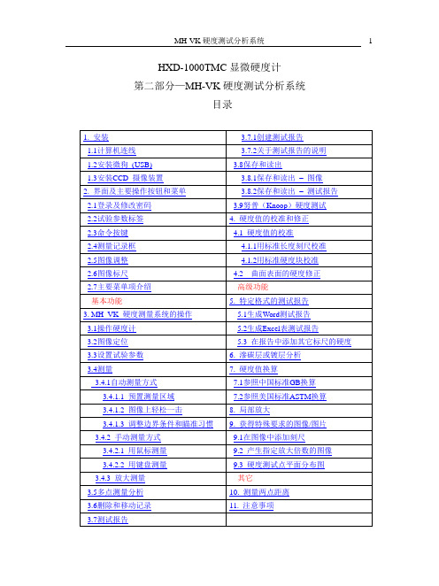
HXD-1000TMC显微硬度计第二部分—MH-VK硬度测试分析系统目录1 安装1.1计算机连线(图1-1)1.2安装微狗(USB)把微狗(USB)插在一个USB接口(15)上,参见图1-2。
硬度测试程序已经安装在计算机上了。
1.3安装CCD 摄像装置全套CCD 摄像装置包括CCD摄像头和DC 12V适配器。
(图1-3)旋下仪器防尘栓(13)。
(参见操作说明书第一部分的图3。
)参见图 !-3 和 图1-4。
把CCD 摄像头的连接管插入仪器的连接孔。
把硬度计上的测量 / 摄像转手转到摄像位置(反时针)。
参见硬度计说明书,第一部分。
CCD 摄像头的DC12V 接口和DC 12V 适配器相连,而CCD 摄像头的Video Out 接口和计算机的AV1接口相连。
(图1-1).把适配器的12VDC output 和CCD 摄像头的 Input 接口相连。
2. 界面及主要操作按钮和菜单 2.1 登录及修改密码如果桌面上提供有硬度测试程序的快捷图标 ,双击该图标,就出现进入硬度测试程序的登录窗口,如图2-3所示。
可以在下面路经找到并打开硬度测试程序:C:\Program Files \ MH_VK_C30 \ MH_VK_C30.exe 。
也可以用:开始\程序\ MH_VK_C30\ MH_VK_C30.exe 。
仪器在出厂时,制造商没有给程序设置密码,即原始密码是空的。
您只要点击一下按钮“确定”,就可进入硬度测试程序。
如果用户想要设置或修改密码,选择菜单项工具/修改密码,就可打开修改密码对话框,如图2-2所示。
如果您设置或修改了密码,请一定记住您的密码。
最好把密码记录下来。
如果您忘记了密码,您将无法打开测试程序。
主窗口的绝大部分用于显示图象或测试报告。
窗口的右边是一些操作按钮和一组指示试验状态或参数的标签。
见图2-3。
图 2-3 MH_VK 硬度测试程序主窗口试验参数标签2.2试验参数标签参见图2-4.(1) 标签 硬度标尺硬度标尺HV 或 HK 可以在右边的下拉列表框中选择。
VISTEK V165X 序列数字视频路由模块用户指南说明书

VISTEK V165X SERIAL DIGITAL VIDEO ROUTER MODULEUSER GUIDE1VISTEK V165X serial digitalvideo router module2Issue 1Contents1. INTRODUCTION........................................................................................................3 1.1 Description.......................................................................................................32.INSTALLATION.........................................................................................................4 2.1 Rear Panel Connections .................................................................................4 2.2 Hardware. (5)2.2.1 Switch and Link Settings.......................................................................53.OPERATION..............................................................................................................9 3.1 Front Panel Indication.....................................................................................9 3.2 Indicators .......................................................................................................11 3.3 Controls. (12)VISTEK V165X serial digital video router moduleHU-V165X 3 1.INTRODUCTION1.1DescriptionThe V165X Serial Digital Video Router Module provides a platform on which several different types of router may be built. All the variants can handle the four main video standard frequencies of 143, 177, 270 and 360 Mbits/s. The outputs are fully re-generated.The range consists of :-The V1651 2x1 SDI router with automatic signal error detection and changeover. The V1652 8x1 SDI router.The V1653 8x1 SDI router with synchronous switching. The V1654 8x8 SDI router with Output monitoring.All the routers can be fed with an analogue external reference signal, but this reduces the 8x1 routers to 7x1's due to the limited rear panel space. If the external reference is not fitted the switching reference will be taken from the currently selected output, so vertical interval switching will be maintained between sources of the same relative timings. The switching line used is user selectable and may be field or frame based.The routers are all provided with front panel controls and indicators. All the modules are provided with the required interface logic for the Dart remote control system and also a simple remote panel interface. (See V1650 Remote Control Manual).The V1651, 2 & 3 modules are 3U high cards and are designed to fit in the V1601 or the V1603 racking systems. The V1654 is also 3U high modules, but is double width, so will only fit in the V1603 rack.The V1651 and V1653 are designed to have clean switching between the sources. The routers achieve this by timing the new source as close to the reference as possible, before switching. The reference is obtained from either the External Reference input (I/P 8), or if not present the currently selected source. (The V1651 may have its clean switching turned off if a reference is not available.)Due to the sources having differing clock phases it is only possible to synchronise the sources within one clock cycle, so if the reference is taken from the sources rather than an external reference the delay through the router can progressively change as sources are selected.VISTEK V165X serial digitalvideo router module4 Issue 1 2.INSTALLATION2.1Rear Panel ConnectionsV1651V1652, V1653V1654PowerThe power is picked up by the input connector panel from the frame to feed the router. The nominal power consumption of each router is:- V1651 8.5W V1652 6W V1653 10W V1654 13.5WIf the V1650 Remote Control Panel Interface is connected the power consumption of the router module is increased by 0.5W.SD1-8 (IN)The Serial Digital Inputs are passed straight through the rear module and terminated in 75 Ohms on the main module. Input 8 on the V1652 and V1653 is shared with the reference input and a zero ohm resistor is fitted on the module to set the operational mode. (R102 - I/P 8, or R103 - Ref). Inputs 2, 4, 5, 6 & 7 are not used on the V1651 and input 8 is set on the main module to the reference mode.SD (OUT)SD1 (IN)SD2 (IN)SD3 (IN)SD4 (IN)SD6 (IN)SD7(IN) SD8 (IN) /REFSD1 (IN) SD2 (IN)SD3 (IN) SD4 (IN)SD5 (IN)SD6 (IN) SD7 (IN) SD8 (IN) MON (OUT)SD1 (OUT)SD2 (OUT)SD3 (OUT)SD4 (OUT)SD5 (OUT)SD6 (OUT)SD7 (OUT) SD8 (OUT) REFSD (OUT)SD1 (IN)REFSD2 (IN)VISTEK V165X serial digital video router moduleHU-V165X 5 REFThe reference input is an analogue video signal of either 1Vp-p video or upto 4Vp-p mixed sync pulses. The signal is passed through the rear module and terminated in 75 Ohms on the input router module.SD (OUT) & SD1-8 (OUT)The outputs are driven directly through the rear module from the input or output router module at 75 Ohm impedance.MON (OUT)The monitoring output is driven directly through the rear module from the input router module at 75 Ohm impedance. This output monitors the output busses of the crosspoint ic and not the inputs to the crosspoint.DART Remote ControlThe DART control interface is picked up by the input rear module from the rack and routed into the input router module.2.2 HardwareThe figure below shows diagramatically the input module, which contains all the control hardware and link selectable variations. Not all components are fitted in every variant, (see text for details). The 8 Output module has no links and is therefore not shown.2.2.1R102 & R103These two resistors are used to control the routing of the signal on input eight to determine if the reference is used or SDI input eight. The modules are shipped in the following configurations:- V1651 R103 Reference Input. V1652 R102 SDI Input eight. V1653 R103 Reference Input. V1654 R102 SDI Input eight.F R O N T P A N E LREAR CONNECTORVISTEK V165X serial digitalvideo router module6Issue 1The V1652 and V1653 may be changed to allow a reference to be used for switching timings or input 8. To change the mode move R102 or R103 to the other position. (A surface mount resistor is used rather than a link to reduce the signal degradation of the SDI signal).The V1651 and V1654 do not require changes to be made as the signal paths are not required for dual purpose use. LK1Link 1 controls the switching frequency of the router between Frame rate and field rate. LK2Link 2 is used to tell the control system which signals are used to obtain the switching reference timing. If the link is set to INT. (Internal) the switching reference timing will be taken off the currently selected video output, or in the absents of a signal the free running clock. When the link is selected to EXT (External) the switching reference timing is taken from the REF. input, but in its absents the router reverts to using the currently selected output or the free running clock.The link is also used on the V1652 and V1653 to instruct the control system as to the number of available SDI inputs. With the link set to INT there are 8 selectable inputs, but with the link set to EXT there are only 7 and the source button eight is ignored by the control system.Note: If the V1654 is running off internal reference the signal used for switching timing is the currentlyselected monitoring output, selected by the local destination panel.SW11Switch 11 is used to assign the line on which the router will switch. (See table below)625 Lines 525 Lines SW11LK1 FRM LK1 FLD LK1 FRM LK1 FLD0 621 621 & 309 525 525 & 263 1 622 622 & 310 1 1 & 264 2 623 623 & 311 2 2 & 265 3 624 624 & 312 3 3 & 266 4 625 625 & 313 4 4 & 267 5 1 1 & 314 5 5 & 268 6 2 2 & 315 6 6 & 269 7 3 3 & 316 7 7 & 270 8 4 4 & 317 8 8 & 271 9 5 5 & 318 9 9 & 272 A 6 6 & 319 10 10 & 273 B 7 7 & 320 11 11 & 274 C 8 8 & 321 12 12 & 275 D 9 9 & 322 13 13 & 276 E 10 10 & 323 14 14 & 277 F 11 11 & 324 15 15 & 278VISTEK V165X serial digital video router moduleHU-V165X 7 SW12Switch 12 is only fitted on the V1651 and the V1653 and can be divided into two halves. The switches 1-4 control the synchroniser delay for both routers and the switches 5-8 are used by the V6151 to determine the conditions for an automatic change over of sources.Switch 1 (V1651 only)This switch turns off the synchronising function and reduces the delay of each channel to a minimum. This is the recommended mode of operation if an external reference is never provided.Switches 2-4These switches control the amount of delay added to the signal path with respect to the reference signal being used. This will allow the synchronising mechanism to time signals early on the reference upto 4000 clock cycles minus the selected delay, or late on the reference upto the selected delay. (See table).Approximate selected delays. (wrt selected reference).SW12 Approx. Delay (us) 2 3 4 143Mbits/s 177Mbits/s 270Mbits/s 360Mbits/s 0n 0n 0n -179, +0.7 -225, +0.5 -147, +0.5 -109, +0.3 0n 0n 0ff -177, +3 -224, +2 -146, +1.5 -109, +1 0n 0ff 0n -173, +7 -220, +6 -144, +3.5 -107, +3 0n 0ff 0ff -264, +16 -213, +13 -139, + 9 -104, +6 0ff 0n 0n -245, +35 -197, +28 -130, +18 -97, +13 0ff 0n 0ff -210, +70 -169, +56 -111, + 37 -83,+27 0ff 0ff 0n -175, +105 -142, +84 -93, +55 -69, +41 0ff 0ff 0ff +140 +113 +74 +55* WARNING * Care should be taken when setting the delay, as picture disturbances will occur if theFIFO minimum or maximum lengths are reached.Switch 5 (V1651 only)This switch allows the unit to select between synchronous and Non-synchronous switching modes according to whether an external reference is present and being used. If the units link 2 is in EXT and a reference is provided the router will operate with synchronous switching. If link 2 is set to INT or the reference is not present the unit will change to non-synchronous mode automatically.VISTEK V165X serial digitalvideo router module8 Issue 1 Switches 6-8These switches are only used on the V1651 to set up the operation of the automatic mode. Switch 6 on Lock Fail Sets the fail condition to occur when the currently selected source does not lock up the re-clocker ic. Switch 7 on EDH Fail Sets the fail condition to occur when multiple EDH errors are detected. An error condition will be set if 3 fields containing EDH errors are detected within 32 fields and cleared once 32 consecutive error free fields are present. Switch 8 on HOLDSets the router to change sources when the current source fails, providing the other source is good, when in AUTO mode. off FLIP/FLOP Sets the router to always select input 1if source 1 is good, when in AUTO mode.VISTEK V165X serial digital video router moduleHU-V165X 93.OPERATION3.1Front Panel IndicationThe REM lamp indicates that the DART control system communications link is active. The +V lamp indicates that power is applied to the module.The 270 lamp indicates that a 270Mbit/s ITU-R Rec.601 serial component video source is selected. The 360 lamp indicates that a 360Mbit/s ITU-R Rec.601 serial component video source is selected.The 143 lamp indicates that a 143Mbit/s ITU-R Rec.601 serial composite video source is selected. The 177 lamp indicates that a 177Mbit/s ITU-R Rec.601 serial composite video source is selected.The EDA lamp indicates an error in the Serial Video Signal which was detected prior to this unit. (Error detected already).The EDH lamp indicates an error in the Serial Video Signal which was detected by this unit. (Error detected here).The Ref. Select button is recessed behind the front panel and is used to re-time the output on the V1651 and V1653 only.Source 1-8 Local selection of input source.Rem Remote control via the Dart control Interface.+ All router source selection controls are inhibited.Loc. Local control from the front panel and the V1650 Remote Control Panel Interface.VISTEK V165X serial digitalvideo router module10Issue 1VISTEK V165X serial digitalvideo router moduleHU-V165X 11 3.2 IndicatorsREMThe REM (Remote) indicator illuminates whenever the module is accessed by the DART control system.This will occur even if the module is under local control.+VThis indicates that the module is powered and producing its internal voltage rail.270, 360, 143, 177When a source is routed through the unit the indicators will show the video frequency standard of the locally selected output, provided the signal is locked in the reclocking ic. If no indicators are on then the signal has not locked up in the reclocker.EDA, EDHThese indicators are used to display Errors that are detected within certain checksums embedded in the Video data stream. They show Full Field errors including ancillary data. The EDA (Error Detected Already) indicator shows that a unit prior to the router has found an error and set the appropriate flag in the video data stream. The EDH (Error Detected Here) indicator shows that the data has got errors between its contents and the inserted checksums. If the video has no checksums inserted the indicators will not illuminate even if there are errors in the path.VISTEK V165X serial digitalvideo router module12Issue 1 3.3 ControlsRef. SelectThis control is a push button recessed behind the front panel on the V1651 and V1653 and is used to reset the video timing delay through these synchronous routers. If the external reference is being used the button, upon release will re-synchronise the video selected to the output. (When a new source is selected this re-timing is done automatically). If the reference is taken from the internal signals, the release of the button will set the output timing to the selected delay from the currently selected output signal. (When a new source is being selected it will automatically time to the current source).Source 1-8These are illuminated push buttons and allow selection of the source to the currently selected destination when the unit is being used in local mode. The buttons illuminate when they are pressed and display the correct source selection when all are released. In Remote (Rem) or + mode the buttons have no effect on the selection. When the router is internally selected to External Reference or it detects an external reference on input eight the selection of this source to the output is prohibited automatically.Destination 1-8These are illuminated push buttons and allow selection of the destination bus for the local control panel on the V1654 only. These button remain active in all modes of remote and local control. The destinationselection controls the output monitoring bus of the router and thus the source for the front panel indications. It monitors the output busses of the crosspoint ic rather than selecting the source routed to that destination.FailThese indicators only appear on the V1651 2x1 router and are used to indicate that the input signal has failed either because of EDH errors or loss of a locked input, according to the settings of the failure mode switches on the board.AutoThe button only appears on the V1651 2x1 router and has a toggle action. When illuminated the router will self switch under source failure conditions, as set by the SW12 switches.Rem, +, LocalThis toggle switch is used to assign which control system is being used to control the router.Rem (Remote) mode inhibits the V1650 Remote Control and the local source controlpanel from operation and only accepts changes made by the DART RemoteControl system.+ Mode The Local Control system and the DART Control are disabled.Local Allows the V1650 Router Remote Control system and the local panel to controlsource selection, but inhibits the DART Remote systems.。
UV-6000使用说明

上海元析仪器有限公司
第四: 第四:标准曲 线测试浓度
第一步: 第一步:根据新建的标准曲线或从仪器调出的 标准曲线 第二步:在标准曲线显示界面下, start建 第二步:在标准曲线显示界面下,按start建 进入浓度测试界面 第三步:将参比液放入光路中, ZERO键调零 第三步:将参比液放入光路中,按ZERO键调零 第四步:将未知浓度样品放入光路中, 第四步:将未知浓度样品放入光路中,按 start键 start键,显示器上显示出相应样品 的浓度, 的浓度,重复上述步骤可完成多个样 品浓度的测试
上海元析仪器有限公司
第三: 第三: 建立标准曲线
第一步:插上电源,打开仪器,预热20分钟 第一步:插上电源,打开仪器,预热20分钟 20 仪器自动跳到操作主界面 第二步:按上下键选择“定量测量”模式, 第二步:按上下键选择“定量测量”模式,再 选 择屏幕下方的“拟合曲线” 择屏幕下方的“拟合曲线”,再选择 屏 幕下方的“标样设定” 幕下方的“标样设定” 第三步: 第三步:依次设定标样浓度 第四步: start键开始 键开始, 第四步:按start键开始,依次采集标样的吸 光度值 第五步:选择屏幕下方的“曲线” 第五步:选择屏幕下方的“曲线”,仪器会自 动 绘制出标准曲线(如果操作有误, 绘制出标准曲线(如果操作有误,标 准曲线绘制不出) 准曲线绘制不出)
上海元析仪器有限公司
样品室
UV-6000的样品室可容纳 的样品室可容纳5mm-100mm 的样品室可容纳 各种规格的比色皿。 各种规格的比色皿。
上海元析仪器有限公司
第一: 第一:测透过率
第一步:插上电源,打开仪器,预热20分钟 第一步:插上电源,打开仪器,预热20分钟 20 仪器自动跳到操作主界面 第二步: 第二步:按上下键调至光度测量模式确认 第三步: 第三步:按GOTOλ键,用数字键盘输入 键 所需波长值, 所需波长值,按ENTER键确认 键确认 第四步:选择屏幕下方的模式项, 第四步:选择屏幕下方的模式项,再选择透 过率模式确认返回 第五步:将空白样品放入光路中, 第五步:将空白样品放入光路中,关上样品 室盖 第六步: 第六步:按ZERO键,调零 键 第七步:将待测样品放入光路中, 第七步:将待测样品放入光路中,关上样品 室盖 第八步: 第八步:从显示器上直接得出透过率值
线切割机床保养手册

ENTER键,开始安装软件,执行过程中每一行后面都应出现 “DONE”字样,执行完后关闭对话框,再双击此文件夹中的 “install” 文件,当电脑提 示“install ok”后软件即安装好了。 2)在安装好的文件中找到FHGD可执行文件,创建快捷方式于桌面,运
高 频 脉 冲 信 号 输 入
电源指示灯,正常 情况下,三只指示 灯应全亮
加工电压及走丝速度 控制信号输出及高频 控制信号输入端口
高频控制信号 指示灯,灯亮 开高频,亮灭 关高频
加工电参数传输出错信号输出 加工结束停机信号输入
加 工 电 压 及 走 丝 速 度 信 号 输 入
5VDC输入
电柜电路板介绍(六)
整流电路 整流电路
XY轴步进电机 UV轴步进电机
电
脑
加工电压取样
高频控制
加工电压取样
及
脉冲信号
高频信号
光电隔
高频电源功
H
高频数据 发生电路 电压信号
离电路 脉冲信号 率放大电路
F 数
(W306) 丝速信号 (W305)
移轴数据 手控盒
(W307/08)
压
速
KM1~KM3
信
信 电压控制
U轴步 进电机 指示灯
V轴步 进电机 指示灯
当单步点动步进电机时,在正常情况下,U轴
指示灯亮次序为:U1 U1U2 U2 2U3 U3 U3U1 U1 循环点亮,V轴也是如此。
V轴步
1
进电机
3
V
H F
U轴对应灯U1
U轴对应灯U3
V轴对应灯V2
交 流
卡
- 1、下载文档前请自行甄别文档内容的完整性,平台不提供额外的编辑、内容补充、找答案等附加服务。
- 2、"仅部分预览"的文档,不可在线预览部分如存在完整性等问题,可反馈申请退款(可完整预览的文档不适用该条件!)。
- 3、如文档侵犯您的权益,请联系客服反馈,我们会尽快为您处理(人工客服工作时间:9:00-18:30)。
引言:
概述:
UVK6视频软件是一款功能强大的视频编辑和处理工具,它提供了多种强大的功能,包括视频剪辑、混音、特效和转码等。
通过使用UVK6视频软件,用户可以轻松编辑和处理各种视频文件,实现个性化的视频创作和制作。
正文内容:
1.功能介绍
1.1视频剪辑功能:
提供直观的界面和简单易用的操作方式,让用户轻松进行视频剪辑。
支持各种视频格式的导入和导出,使用户可以灵活地处理各种视频文件。
提供丰富的视频剪辑工具,包括剪切、拼接、分割和调整视频长度等。
1.2混音功能:
内置多种音频特效,可以轻松实现音频的增强、降噪和淡入淡出等处理。
支持多轨道混音,用户可以将多个音频文件进行叠加和混合,实现更丰富的声音效果。
提供直观的音频编辑界面,让用户可以精确地调整音频的音量、音调和平衡等参数。
1.3视频特效功能:
提供多种视频特效效果,包括滤镜、转场和字幕等,让用户可以轻松实现视频画面的优化和个性化处理。
支持实时预览功能,用户可以即时查看和调整特效效果,提高编辑效率。
提供丰富的特效库,用户可以根据自己的需求选择和应用各种特效效果。
1.4视频转码功能:
支持将视频文件转换为多种格式,包括常见的MP4、AVI和MOV 等,提供了广泛的输出选项。
提供高质量的视频编码技术,保证了转码过程中画质的保持和视频文件的稳定性。
提供可调节的视频参数选项,包括分辨率、帧率和比特率等,让用户可以根据自己的需求进行定制。
2.使用方法
2.1安装和启动:
UVK6视频软件的安装文件并运行,按照提示完成软件的安装过程。
双击桌面上的UVK6视频软件图标启动软件,进入软件主界面。
2.2导入和编辑视频:
主界面上的“导入”按钮,选择要编辑的视频文件并导入到软件中。
在时间轴上选择视频片段,并使用剪切、拼接和分割等工具进行编辑。
2.3调整音频效果:
主界面上的“音频”选项,进入音频编辑界面。
使用音频效果菜单和参数调节栏对音频进行增强、降噪和混音等处理。
2.4应用视频特效:
主界面上的“特效”选项,进入特效编辑界面。
选择要应用的特效效果,并调整其参数,实时预览并应用到视频中。
2.5输出和保存:
主界面上的“导出”按钮,选择输出格式和保存路径。
根据需要调整输出参数,并“开始导出”按钮将视频保存到指定路径。
3.常见问题解答
3.1如何解决导入视频文件失败的问题?
检查视频文件格式是否与软件支持的格式一致。
确保视频文件没有损坏或受到保护,尝试重新导入。
3.2如何解决视频导出过程中出现的画质损失问题?
调整导出参数,选择合适的分辨率、帧率和比特率。
确保原始视频文件的画质良好,避免使用压缩过多的视频文件。
3.3如何实现视频剪辑的精确控制?
使用时间轴上的标记功能,可以精确选择和编辑视频片段。
使用剪切、拼接和分割等工具进行细致的视频剪辑。
3.4如何应用多个视频特效?
在特效编辑界面,可以依次选择和应用多个特效效果。
调整特效参数和叠加模式,实现多个特效的组合效果。
3.5如何调整音频的音量和音调?
在音频编辑界面,可以使用音频参数调节栏对音量和音调进行调整。
通过实时预览功能,判断音频效果的准确性和满意度。
总结:
UVK6视频软件是一款功能强大的视频编辑和处理工具,通过本文详细介绍了其功能特点、使用方法以及常见问题解答等内容。
通过学习和掌握UVK6视频软件的使用,用户可以轻松完成各种视频编辑和处理任务,并实现个性化的视频创作和制作。
希望本文对用户有所启发和帮助,使用户能更好地利用UVK6视频软件为自己的视频创作增添色彩。
引言概述:正文内容:
1.视频介绍:
1.UVK6视频的定义和功能。
2.UVK6视频的适用范围。
3.UVK6视频的特点和优势。
2.安装与配置:
1.系统要求。
2.和安装UVK6视频。
3.注册和激活。
4.软件界面和设置。
3.主要功能:
1.视频剪辑和合并。
2.视频特效和滤镜。
3.视频转换和导出。
4.视频调整和修复。
5.视频字幕和水印。
4.高级功能:
1.视频动画和转场效果。
2.视频蒙版和遮挡。
3.视频分屏和画中画。
4.视频音频处理和编辑。
5.视频字幕和水印样式定制。
5.使用技巧:
1.快速剪辑和拖放编辑技巧。
2.高级特效和滤镜应用技巧。
3.快速导出和批量处理技巧。
4.视频颜色校正和调整技巧。
5.视频字幕和水印设置技巧。
总结:。