插件电容规格书
插件电容规格型号对照表

插件电容规格型号对照表插件电容是一种常用的电子元件,用于存储和释放电荷以及滤波等电路应用。
在电子设备的设计和维修中,选择合适的插件电容非常重要。
为了帮助大家更好地了解不同型号的插件电容,本文将提供一个插件电容规格型号对照表,以便大家在实际应用中能够准确选择合适的插件电容。
一、对照表以下是一个插件电容规格型号对照表,包含了常用的插件电容型号及其规格参数:型号容量(μF)电压(V)尺寸(mm)电极间距(mm)C1 1 50 6.3x11 2.5C2 2.2 50 7.3x13 2.5C3 4.7 50 7.3x13 2.5C4 10 50 9x15 5C5 22 50 11x19 5C6 47 50 13x21 5C7 100 50 16x25 7.5二、插件电容规格解读1. 容量(μF):容量是指插件电容可以存储的电荷量,单位为微法(μF)。
容量越大,插件电容可以存储的电荷量越多。
2. 电压(V):电压是插件电容可以承受的最大电压,单位为伏特(V)。
超过额定电压会导致插件电容损坏或发生故障,因此选择合适的电压等级非常重要。
3. 尺寸(mm):尺寸是指插件电容的外形尺寸,单位为毫米(mm)。
在实际应用中,需要根据电路板和元器件的尺寸要求来选择合适的插件电容。
4. 电极间距(mm):电极间距是指插件电容两个电极之间的距离,单位为毫米(mm)。
电极间距需要与电路板上的焊盘尺寸相匹配,以确保插件电容可以正确焊接在电路板上。
三、插件电容的选择和应用在实际应用中,选择合适的插件电容需要考虑以下几个因素:1. 容量选择:根据电路设计的要求,选择合适的容量。
如果需要存储大量的电荷,可以选择较大容量的插件电容。
2. 电压等级:根据电路的工作电压,选择符合要求的电压等级。
如果电压超过插件电容的额定电压,会导致插件电容损坏或发生故障。
3. 尺寸匹配:根据电路板和元器件的尺寸要求,选择合适尺寸的插件电容。
尺寸太大或太小都会导致插件电容无法正确安装在电路板上。
插件国巨电阻规格书
Page-1Approval SheetforCarbon Film ResistorsCFR series±2% & ±5%YAGEO CORPORATIONHeadquarters: 3F, No.233-1, Pao Chiao Rd., Shin Tien, Taipei, Taiwan,R.O.C.Tel: 886-2-2917-7555 Fax: 886-2-2917-4286URL: Page-2Page-31. PRODUCT : CARBON FILM RESISTORS(Normal & Miniature Style)2. PART NUMBER : Part number of the carbon film resistor is identified by the name,power, tolerance, packing, temperature coefficient, special type and resistance value.Example :CFR -12 J T J 52 100RSeries Size Resistance Packing Temperature Special ResistanceName Code Tolerance Style Coefficient Type Value of Resistance(1) Style: CFR SERIES(2) Power Rating: -12=1/6W 、25S=1/4WS 、-25=1/4W 、50S=1/2WS 、-50=1/2W 、 1WS=1WS 、100=1W 、2WS=2WS 、200=2W(3) Tolerance: G=±2% J=±5%(4) Packaging Type : R =Paper Taping Reel T =Tape on Box Packing B =Bulk Packing(5) T .C .R : J=±350ppm/℃ — =lgnore(6) Special Type : 26=26mm 、52=52.4mm 、73=73mm 、 PN =PANAsert AV =AVlsert(7) Resistance Value: 1R 、10R 、100R 、10K 、100K 、330K 、1M………Page-43. BAND-CODE:4. ELECTRICAL CHARACTERISTICSTabe I*Standard resistance is 1Ω~ 10M Ω, below or over this resistance on request. *Rated Continuous Working Voltage (RCWV)=Value Resistance Rating Power ×FIG.1 TEMPERATURE COEFFICIENTPage-55. DERATING CURVE & HOT-SPOT TEMPERATURE6. DIMENSIONS7. ENVIRONMENTAL CHARACTERISTICS(1) Short Time Over Load TestAt 2.5 times of the rated voltage. (If the voltage exceeds the maximum load voltage, the maximum load voltage will be used as the rated voltage) applied for 5 seconds, the resistor should be free from defects after the resistor is released from load for about 30 minutes and the change of the resistance value should be within ±(0.25%+0.05Ω) as compared with the value before the test.Page-6(2) Dielectric Withstanding VoltageThe resistor is placed on the metal V Block. Apply a Table I dielectric withstanding between the terminals connected together with the block for about 60 seconds. The resistor shall be able to withstand without breakdown or flashover.(3) Temperature Coefficient TestTest of resistors above room temperature 125°C to 130°C (Testing Temperature) at the constant temperature silicon plate for over 4 to 5 minutes. Then measure the resistance. The Temperature Coefficient is calculated by the following equation and its value should be within the range of requested.600010t t 1R R R t Coefficien e Temperatur sistor Re ×−×−=R= Resistance value under the testing temperature R 0= Resistance value at the room temperature t = The testing temperature t o = Room temperature(4) Insulation ResistanceApply test terminal on lead and resistor body. The test resistance should be high than 10,000 Mohm.(5) SolderabilityImmerse the specimen into the solder pot at 230±5°C for 5±0.5 seconds. At least 95% solder coverage on the termination.(6) Resistance to SolventThe specimen into the appropriate solvent of Methyleme Chloride condition ofultrasonic machine for 1 minutes. The specimen is no deterioration of coatings and color code.(7) Terminal StrengthDirect Load – Resistors shall be held by one terminal and the load shall be gradually applied in the direction of the longitudinal axis of the resistor unit the applied load reacheds 5 pounds. The load shall be held for 10 seconds. The load of weight shall be ≧2.5kg(24.5N).Page-7(8) Pulse OverloadApply 4 times of rated voltage to the specimen at the 1 second on and 25 seconds off cycle, subjected to voltage application cycles specified in 10000. The change of the resistance value shall be within ±(2%+0.05Ω).(9) Load Life in HumidityPlace the specimen in a test chamber at 40±2°C and 90~95% relative humidity. Apply the rated voltage to the specimen at the 1.5 hours on and 0.5 hour off cycle. The total length of test is 1000 hours. The change of the resistance value shall be within ±(1.5%+0.05Ω).(10) Load Life TestPlaced in the constant temperature chamber of 70±3°C the resistor shall be connected to the lead wire at the point of 25mm. Length with each terminal, the resistors shall be arranged not much effected mutually by the temperature of the resistors and the excessive ventilation shall not be performed, for 90 minutes on and 30 minutes off under this condition the rated D.C. voltage is applied continuously for 1000+48/-0 hours then left at no-load for 1hour, the change of the resistance value measured at this time to the value before the test shall be within ±(1.5%+0.05Ω). There shall be no remarkable change in the appearance and the color code shall be legible after the test.(11) Temperature Cycling TestThe temperature cycle shown in the following table shall be repeated 5 times consecutively. The measurement of the resistance value is done before the first cycle and after ending the fifth cycle, leaving in the room temperature for about 1 hour, the change shall be within ±(1%+0.05Ω). After the test the resistor shall be free from the electrical or mechanical damage.Temperature Cycling Conditions: Step Temperature(°C) Time (minute)1 +25+10 -5 10 to152 -65+0 -3 30 3 +25+10 -5 10 to15 4+150+3 -030Page-8(12) Resistance to Soldering HeatThe terminal lead shall be dipped into the solder pot at 350±10°C for 3±0.5 seconds up to 3 mm. The change of the resistance value shall be within ±(1%+0.05Ω).8. PACKING METHODS Bandolier for Axial leadsThe resistors are supplied on bandolier, either 1000 resistors in ammopack or 5000 resistors on reel.9. TAPE ON REEL PACKING & TAPE ON BOX PACKING10. SPECIAL TYPE (FORMING DIMENSIONS)。
CGA5L1X7R1H106K160AC规格书

其他 流体 回流 Yes 塑封编带 (180mm卷筒) 2000pcs
! Images are for reference only and show exemplary products. ! This PDF document was created based on the data listed on the TDK Corporation website. ! All specifications are subject to change without notice60AC
电容
CGA5L1X7R1H106K160AC
DC偏置特性
CGA5L1X7R1H106K160AC
温度特性
CGA5L1X7R1H106K160AC 纹波温度上升
CGA5L1X7R1H106K160AC(No Bias) CGA5L1X7R1H106K160AC(DC Bias = 25 )
Copyright(c) TDK Corporation. All rights reserved.
积层贴片陶瓷片式电容器 CGA5L1X7R1H106K160AC
Associated Images
Land Pattern (Terminal Connection)
3 of 3 Creation Date : April 23, 2020 (GMT)
推荐焊盘布局(PB)
推荐焊盘布局(PC)
电容 额定电压 温度特性 耗散因数 (Max.) 绝缘电阻 (Min.)
焊接方法
AEC-Q200 包装形式 包装个数
1 of 3 Creation Date : April 23, 2020 (GMT)
独石电容104K规格书

频率
电容量抽样检验
合格数量 不合格数量
机 型 数 量 绝缘电阻抽样检验
合格数量 不合格数量
10pcs 占比例 0pcs 占比例 合格 检验者 焊锡性
外观抽样 形 状
检验结果记录
盖检验章√Βιβλιοθήκη ¢0.5mm 10 Pcs
电介质种类 X7R 检测日期 110nF 90nF 100% 0% 100VDC 湿度 100% 0% <80% 260 ℃ 核准者
1KHZ1.0V
总数量
pcs 抽样数量 机 型 数 量
TH2617 最高容量 10pcs 最低容量 10pcs 占比例 0pcs 占比例 TH2681 10pcs 电 压 档 位
深圳市陈氏光星电子科技有限公司
插件独石电容承认书 抽检日期 2010.06.11 客户名称 规格型号 电容容量
CT4-0805B104K
产品名称 独石电容 批号 容 差 ± 10 % 测试温度 额定电压 20-25℃ 50VDC 100nF
W: 0.8 mm
片芯尺寸 L: 1.6 mm 导线尺寸
T: 0.8 mm
wima电容规格书

Polypropylene (PP) Film and Foil Capacitors for Pulse Applications in PCM 7.5 mm to 15 mmPulse duty constructionVery low dissipation factorNegative capacitance changeversus temperatureVery low dielectric absorptionAccording to RoHS 2002/95/ECTypical ApplicationsFor high frequency applications e.g.Sample and holdTimingLC-FilteringOscillating circuitsAudio equipmentDielectric:Polypropylene (PP) filmCapacitor electrodes:Metal foilInternal construction:Encapsulation:Solvent-resistant, flame-retardentplastic case with epoxy resin seal, UL94 V-0Terminations:Tinned wireMarking:Colour: Red. Marking: Black. Epoxyresin seal: Yellow.Capacitance range:100 pF to 0.22 μF(E12-values on request)Rated voltages:63VDC, 100VDC, 250VDC, 400VDC,630VDC, 1000VDCCapacitance tolerances:±20%, ±10%, ±5%Operating temperature range:-55°C to +100°CTest specifications:In accordance with IEC 60384-13 andEN 131800Climatic test category:55/100/56 in accordance with IECInsulation resistance at +20°C:> 5 x 10⁵ M(mean value: 1 x 10⁶ M)Measuring voltage:Ur = 63V: Utest = 50 V/1 min.Ur > 100V: Utest = 100 V/1 min.Dissipation factors at +20°C: tanTest voltage:2 Ur, 2 secMaximum pulse rise time:1000 V/μsec for pulses equal to the ratedvoltageDielectric absorption:0.05%Temperature coefficient:-200 x 10-6/°C (typical)Voltage derating:A voltage derating factor of 1.35% per Kmust be applied from +85°C for DC voltagesand from +75°C for AC voltages.Reliability:Operational life > 300000 hoursFailure rate < 5 fit (0.5 x Ur and40°C)Graphs:Soldering:Mechanical Tests PackingPull test on leads:10 N in direction of leads according toIEC 60068-2-21Vibration:6 hours at 10...2000Hz and 0.75mmdisplacement amplitude or 10g inaccordance with IEC 60068-2-6Low air density:Available taped and reeled.Detailed taping information:Example for ordering / Part number:1kPa = 10 mbar in accordance with IEC60068-2-13Bump test:4000 bumps at 390 m/sec2 inaccordance with IEC 60068-2-29Permissible AC voltagein relation to frequency at 10°C internal temperature rise (general guide)Polypropylene (PP) Capacitors for Pulse Applications with Double-Sided Metallized Electrodes and Schoopage Contacts inPCM 7.5 mm to 37.5 mmPulse duty constructionSelf-healingVery low dissipation factor Negative capacitance changeversus temperature According to RoHS 2002/95/ECTypical ApplicationsFor pulse applications e.g. Switch mode power suppliesTV and monitor setsLightingAudio/video equipmentConstructionDielectric:Capacitance range: 1000 pF to 15 μF (E12-values on request)Rated voltages:100VDC, 250VDC, 400VDC, 630VDC, 1000VDC, 1600VDC, 2000VDC,2500VDCCapacitance tolerances:±20%, ±10%, ±5% Operating temperature range:-55°C to +100°C Climatic test category: 55/100/56 in accordance with IEC Insulation resistance at +20°C: C < 0.33 μF: > 1 x 10⁵ MTest voltage: 1.6 Ur, 2 sec Dielectric absorption:0.05% Voltage derating:A voltage derating factor of 1.35% per K must be applied from +85°C for DCvoltages and from +75°C for AC voltages.Reliability:Operational life > 300000 hours Failure rate < 1 fit (0.5 x Ur and 40°C)Polypropylene (PP) filmCapacitor electrodes:Double-sided metallized plastic filmInternal construction:Encapsulation:Solvent-resistant, flame retardent plastic case with epoxy resin seal, UL 94 V-0Terminations:Tinned wireMarking:Colour: Red. Marking: Black. Epoxyresin seal: Red. (mean value: 5 x 10⁵ M)C > 0.33 μF: > 30000 sec (M xμF)(mean value: 100000 sec)Measuring voltage: 100V/1 min.Dissipation factors at +20°C: tanMechanical Tests PackingPull test on leads:d < 0.8 ?: 10 N in direction of leadsd > 0.8 ?: 20 N in direction of leadsaccording to IEC 60068-2-21Vibration:6 hours at 10...2000Hz and 0.75mmdisplacement amplitude or 10g inaccordance with IEC 60068-2-6Low air density:1kPa = 10 mbar in accordance with IEC60068-2-13Bump test:4000 bumps at 390 m/sec2 in accordancewith IEC 60068-2-29Available taped and reeled up to andincluding case size 15x26x31.5 / PCM27.5mm.Detailed taping information:Example for ordering / Part number:Permissible AC voltage in relation to frequency at 10°C internal temperature rise(general guide)。
插件电容封装规格尺寸

插件电容封装规格尺寸
1. 插件电容的封装规格尺寸一般以毫米(mm)为单位进行表示。
2. 封装形式:插件电容通常采用直插式封装形式,即通过直接插入PCB板上的孔洞进行固定。
3. 引脚数量:插件电容的引脚数量根据其容量大小和功能需求来决定。
常见的有两针、三针、四针等。
4. 引脚间距:插件电容的引脚间距一般为2.54mm(常规间距)或
5.08mm(大间距)。
5. 外壳尺寸:插件电容的外壳尺寸在不同厂家和不同型号之间可能存在差异。
常见的外壳尺寸包括:直径为5mm、7mm、10mm等。
6. 高度尺寸:插件电容的高度尺寸一般指从PCB板上表面到插件电容顶部的距离。
常见的高度尺寸为
7.5mm、10mm、12.5mm等。
7. 其他尺寸参数:插件电容的其他尺寸参数可能包括引脚长度、引脚过插深度等,具体根据不同型号而定。
请注意,以上规格尺寸仅为一般参考,实际应用中还需按照具体需求和供应商的规格进行选型。
超级电容产品规格书
®KAMCAP
Create PDF files without this message by purchasing novaPDF printer ()
Kamcap supercapacitor product specification τ 充电至0.632×UR的时间(s); R 串联电阻(Ω)。 选择R值使τ为60s~120s。 (7)设备:开关 直流电压表 电阻 函数记录仪
其中
C 容量(F);
I 放电电流(A);
U1 测量初始电压(V); U2 测量终止电压(V); t1 放电初始到电压达到U1(s)的时间; t2放电初始到电压达到U2(s)的时间。 放电电流I及放电电压下降的电压U1和U2参见表2。
表2 – 放电条件
分类
HT、HV、X
SE、HE
SP、MK
LR、HP、HEV、LEV
■
®KAMCAP
Create PDF files without this message by purchasing novaPDF printer ()
Kamcap supercapacitor product specification 1 适用范围SCOPE:
Kamcap supercapacitor product specification
11 KAMCAP性能测试方法 (1)依据标准
IEC 62391-1《Fixed electric double-layer capacitors for use in electronic equipment – Part 1:Generic specification》
SE-5R5-D224VY 50
800
4800 270×195×95 415×295×310
宇阳电容规格书
P Q R
1.60+0.40-0.0 2.00±0.20 2.50±0.20
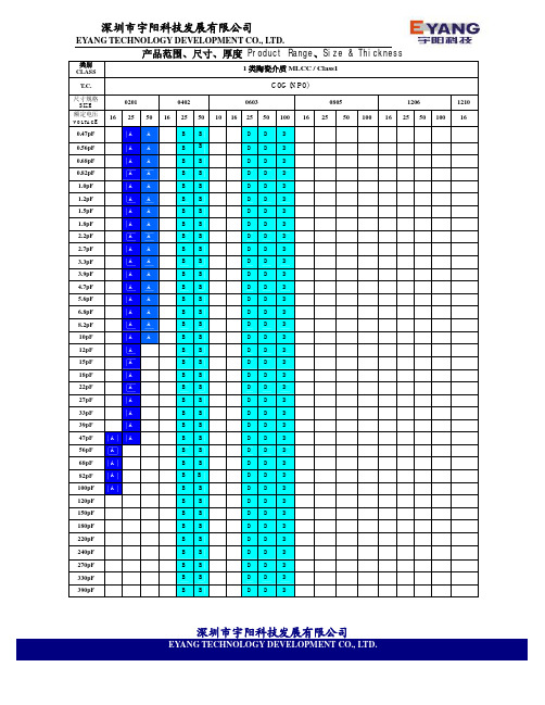
2 类陶瓷介质 MLCC / Class2
X7R
0201
25 50 16
0402
25 50 16 25
0603
50 100 16 25
0805
50 100 16
1206
25 50
深圳市宇阳科技发展有限公司
EYANG TECHNOLOGY DEVELOPMENT CO., LTD.
类别 CLASS T.C. 尺寸规格 SIZE 额定电压
VOLTAGE 6 . 3 0201 10 4 6.3
2 类陶瓷介质 MLCC / Class2
X5R
0402
10 16 25 6.3
0603
10 16 25 6.3 10
0805
16 25 50 6.3 10
1206
16 25 50 16
1210 25 50
0805
50 100 16
1206
25 50
E G G G G G G
G
F L L L L L L L L
L L L L L L L L L
L
标称电容量符合 E12 系列
厚度 代码 厚度 mm 厚度 代码 厚度 mm 厚度 代码 厚度 mm
深圳市宇阳科技发展有限公司
EYANG TECHNOLOGY DEVELOPMENT CO., LTD.
深圳市宇阳科技发展有限公司
EYANG TECHNOLOGY DEVELOPMENT CO., LTD.
39nF 47nF 56nF 68nF
B B B B B B D D D D D D D D D D D D
- 1、下载文档前请自行甄别文档内容的完整性,平台不提供额外的编辑、内容补充、找答案等附加服务。
- 2、"仅部分预览"的文档,不可在线预览部分如存在完整性等问题,可反馈申请退款(可完整预览的文档不适用该条件!)。
- 3、如文档侵犯您的权益,请联系客服反馈,我们会尽快为您处理(人工客服工作时间:9:00-18:30)。
CD11型产品规格书CD11 Series Product Specification一、适用范围 Adapt Range本产品规格书适用于chang 牌CD11型铝电解电容器产品。
±20% (120Hz, +20℃)漏电流Leakage currentFor capacitance value >1000μF, add 0.02 per another 1000μFU R (V) 6.3 10 16 25 35 50 63 100 Z-25℃/Z+20℃ 5 4 3 2 2 2 2 2 Z-40℃/Z+20℃1210854333U R (V)160200250400450Z-25℃/Z+20℃ 3 3 4 8 10Z-25℃/Z+20℃,容量大于1000μF 者,每增加1000μF 阻抗比增加0.5 For capacitance value > 1000μF,Add 0.5 per another 1000μF for Z-25°C/ Z+20℃ Z-40℃/Z+20℃,容量大于1000μF 者,每增加1000μF 阻抗比增加1.0For capacitance value >1000μF,Add 1.0 per another 1000μF for Z -40℃/ Z+20℃续上表六、标称电容量、额定电压、浪涌电压与外形尺寸对应表Nominal capacitance, rated voltage, surge voltage and case size table.六、标志 Marking七、铝电解电容器的使用注意事项 Guidelines For Using Aluminum Electrolytic Capacitor为使您获得电解电容器的最佳性能和延长电解电容器的使用寿命,在使用电解电容器器前,请务必阅读本注意事项。
Upon using Aluminum Electrolytic Capacitors ,please proper handing and observing to following important points will insure optimum capacitor performance and long life.1、直流电解电容器是有极性的 DC electrolytic capacitors are polarized.① ② ③确定极性,极性标志在电容器的基体上。
以免因极性反可能引起电路短路或电容器损坏,当极性不固定或不确定的,使用双极性电容器。
注意直流电解电容器不能使用于交流。
Make sure of the polarity .The polarity is marked on the body of the capacitor .Application of the reversed voltage cause a short circuit or damage to the capacitor .Use bipolar capacitors when the polarity is not determined or unknown . Note that DC electrolytic capacitors can not be used for AC application .2、使用电压不要大于额定电压Do not apply voltage greater than rated voltage .使用电压大于额定电压,漏电流会增大,可能损坏电容器。
建议工作电压为额定电压的百分之七十~八十,电容器在建议的工作电压下使用可延长电容器的寿命。
If a voltage exceeding the rated voltage is applied ,the leakage current will increase , which damage the capacitor . Recommended working voltage is 70 to 80 percent of tatted voltage . Using capacitors at recommended working voltage prolongs capacitor life .3、不要使过量的纹波电流通过电容器Do not allow excessive ripple current through the capacitor .流过电容器的纹波电流超过许可值,将会引起电容器发热,电容量减少,损害电容器。
通过电容器的纹波电流不要大于允许值。
The flow of ripple current over permissible ripple current will cause heat of the capacitor ,which may decrease the capacitance and damage the capacitor .ripple current on the capacitor must be at or bellow allowable level .4、快速的充放电电路中,使用专门设计的电容器Use specially designed capacitors for the circuits where charge and discharge are frequency repeated .在经受快速的周期性充放电电路中,电容器可能受损害,它的寿命因容量下降、温升等原因而缩短,在这种电路中,一定要使用专门设计的电容器。
In the circuit subjected to rapid charge cycles ,capacitors may be damaged ,its life may be shortened by capacitance decrease ,heat rise , ect . Be sure and use special capacitors in these applications .5、工作温度范围Operating temperature range .电容器的特性随工作温度而变化,在温度较高的情况下,容量、漏电流增大,损耗减少;在低温情况下,容量和漏电流下降,损耗增大。
电容器在较低的温度下使用会确保延长寿命。
The characteristics of capacitors change with the operating temperature .The capacitance and leakage current increase and tgδdecrease at higher temperatures . The capacitance and leakage current decrease and tgδat increase lower temperature .Usage at lower temperature will ensure longer life .6、核对工作频率Check operating frequency .电解电容器的容量通常是在100Hz或120Hz下测得的。
然而要记住容量随频率的升高而下降,tgδ随频率的升高而增大,并使周围温度升高。
The capacitance of electrolytic capacitors is usually measured at 100Hz or 120Hz . However ,remember that capacitance decrease and tgδincrease as the applied frequency becomes higher whereas the ambient temperature becomes higher .7、长时间存放的电容器,在使用前加额定直流电压处理Apply rated DC voltage treatment to the capacitors which have been stored for a long time .长时间的存放,实际对电容器的容量和tgδ没有多大的影响,然而往往会使漏电流增大,耐压降低。
长时间存放后的电容器处理,首先逐渐施加直流电压至额定电压,然后再使用。
Long periods of storage have virtually no ef fect no a capacitor’s capacitance and tgδ.Such periods tendhowever ,to increase leakage current and decrease withstand voltage .After removing capacitors fromlong-duration storage ,first apply a gradually increasing DC voltage to rated voltage and then use them.8、电容器外壳与阴极端是不绝缘的The capacitor case is not insulated from the cathodeterminal .电容器外壳与阴极端是通过电解液连接的,如果电容器的外壳必须与线路绝缘,则电容器的安装位置处,一定要采取绝缘出措施。
The capacitor’s case and cathode terminal connect through the electrolyte .If the case is to be completely insulated ,that insulation must be at the capacitor’s mounting point .9、电容器的端子或引线上不要施加过大的力Do not apply excessive force to the terminals and leads.过大的力施加到端子和引线上,可能引起引线的断裂或端子分裂,转而会引起内部连接的破坏。
The excessive strong force applied to the terminals and lead wires may cause leads to break or terminals to separate and ,in turn ,cause the internal contact to fail.CD11型产品规格书CD11 Series Product Specification 测试数据。