03_模块使用说明_CAN
CSM300(A)隔离SPI UART转CAN模块用户手册说明书

CSM300(A)隔离SPI / UART 转CAN 模块修订历史目录1. 功能简介 (1)1.1概述 (1)1.2产品特性 (1)1.3产品型号 (1)1.4应用场合 (1)2. 硬件说明 (2)2.1产品外观 (2)2.2引脚定义 (2)2.3IO说明 (3)2.4SPI转CAN硬件电路 (3)2.5UART转CAN硬件电路 (4)2.6外围保护电路 (5)2.7推荐组网方式 (7)3. 产品应用 (8)3.1名词解释 (8)3.2工作模式 (8)3.2.1SPI转CAN模式 (9)3.2.2UART转CAN模式 (13)3.2.3SPI配置模式 (13)3.2.4UART配置模式 (13)3.3数据转换方式 (13)3.3.1透明转换 (13)3.3.2透明带标识转换 (22)3.3.3自定义协议转换 (27)4. 产品配置 (33)4.1配置参数 (33)4.1.1转换参数 (33)4.1.2SPI参数 (33)4.1.3UART参数 (34)4.1.4CAN参数 (34)4.2出厂默认配置 (35)4.3配置通信协议 (36)4.3.1写配置参数 (36)4.3.2验证产品硬件标识 (39)4.3.3读配置参数 (40)4.4配置方式 (41)4.4.1MCU配置方式 (41)4.4.2上位机配置方式 (42)5. 辅助开发工具 (44)5.1CSM300CFG配置软件 (44)5.2CSM-Eval评估板 (45)5.3上位机配置实例 (46)6. 产品使用注意事项 (49)7. 免责声明 (50)CSM300(A)1.1 概述CSM300(A)系列隔离SPI / UART转CAN模块是集成微处理器、CAN收发器、DC-DC 隔离电源、信号隔离于一体的通信模块,当用户控制板上的CAN控制器资源不够时,可以通过SPI或UART接口扩展出更多的CAN总线接口。
该产品可以很方便地嵌入到具有SPI或UART接口的设备中,在不需改变原有硬件结构的前提下使设备获得CAN通讯接口,实现SPI设备或UART设备和CAN总线网络之间的数据通讯。
VDB03蓝牙信标使用手册说明书
VDB03蓝牙信标使用手册VDB03Bluetooth BeaconUser ManualVDB03蓝牙信标使用手册标题/TitleVDB03Bluetooth Beacon User Manual文档类型/Document type使用手册/User Manual文档编号/Document number WN-22030064版本日期/Revision and date V1.0213-Apr-2022秘密等级/Disclosure restriction公开/Public历史版本/Revision History修订/Revision描述/Description修改人/Modifier日期/Date V1.01初始版本/Initial release Charles20220325 V1.02更新电池使用寿命/Update battery life Charles20220413设备清单/Product List设备名称/Device Name型号/Device No.数量/Number备注/Remark蓝牙Beacon VDB031PCS带防拆按键/With an anti-disassembly button纽扣锂金属电池/ Button lithium metal battery CR20321PCS可拆卸、不可充电电池/Removable,non-rechargeable battery95Power保留本文档及本文档所包含的信息的所有权利。
95Power拥有本文档所述的产品、名称、标识和设计的全部知识产权。
严禁没有征得95Power的许可的情况下复制、使用、修改或向第三方披露本文档的全部或部分内容。
95Power对本文档所包含的信息的使用不承担任何责任。
没有明示或暗示的保证,包括但不限于关于信息的准确性、正确性、可靠性和适用性。
95PowerB可以随时修订这个文档。
可以访问获得最新的文件。
CAN总线报文记录与无线数传设备系列产品用户手册说明书
CANDTU-100URCAN 总线报文记录与无线数传设备系列产品修订历史目录1. 产品简介 (1)1.1产品概述 (1)1.2产品特性 (2)1.3典型应用 (2)2. 产品规格 (3)2.1电气参数 (3)2.2工作温度 (3)2.3防护等级 (3)2.4机械尺寸 (4)3. 产品硬件接口说明 (5)3.1接口布局 (5)3.2DB9接口、法兰端子接口 (5)3.2.1电源接口 (5)3.2.2CAN-Bus接口 (6)3.3USB接口 (8)3.4SD卡接口 (8)4. 配置工具安装与介绍 (9)4.1软件安装 (9)4.2功能说明 (11)4.2.1设备选择 (12)4.2.2CAN配置 (12)4.2.3DO配置 (13)4.2.4过滤 (14)4.2.5触发器(记录模式) (16)4.2.6数据转换器 (18)4.2.7菜单操作 (20)4.2.8设置、获取设备时钟 (21)4.2.9下载、获取设备配置 (22)4.2.10暂停、恢复记录 (22)4.2.11清空设备存储 (22)4.2.12设备信息 (23)5. USBCAN功能使用方法 (24)5.1CANTest测试软件的安装 (24)5.2USBCAN功能的快速使用演示 (25)6. 快速使用说明 (28)6.1操作指南 (28)6.1.1配置 (28)6.1.2记录 (28)6.1.3升级 (28)6.1.4换卡 (28)产品问题报告表 (29)产品返修程序 (30)免责声明 (31)1. 产品简介1.1 产品概述CAN总线故障排查中,最大的难点就是偶发性故障。
这让工程师甚至CAN专家都无法准确判断问题的源头。
比如,风力发电机变桨系统在72小时中发生1次CAN数据传输中断;新能源车辆在行驶1万公里过程中出现1次仪表盘“黑了”,但后来怎么都无法复现;高铁列车在行驶2000公里中出现1次由于CAN通讯异常而导致的紧急减速等。
这些偶发性的CAN通讯异常就像定时炸弹,让工程师胆战心惊。
CANopen
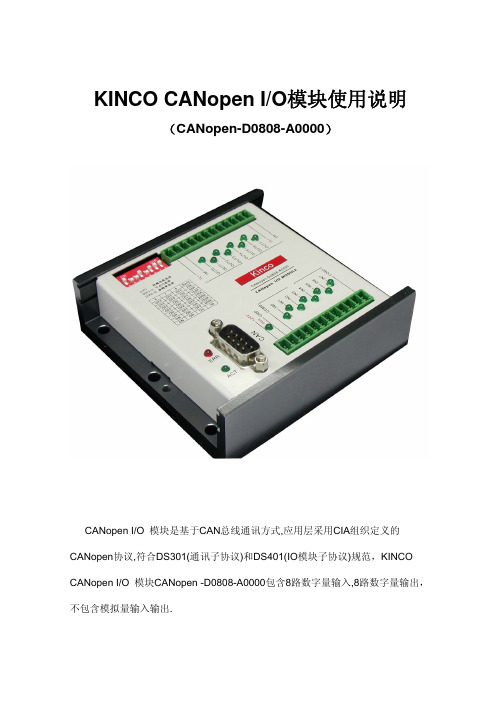
KINCO CANopen I/O模块使用说明(CANopen-D0808-A0000)CANopen I/O 模块是基于CAN总线通讯方式,应用层采用CIA组织定义的CANopen协议,符合DS301(通讯子协议)和DS401(IO模块子协议)规范,KINCO CANopen I/O 模块CANopen -D0808-A0000包含8路数字量输入,8路数字量输出,不包含模拟量输入输出.本模块的电气参数如下:1) 可通过SDO进行参数配置(见后面列表);2) 供电电源:12~24VDC3) 8路输入:光电(双向光耦)隔离;4路一组公用一个公共端,两个公共端彼此隔离;输入电平范围:12~24VDC,输入电流>4mA;输入响应时间:10ms;4) 8路输出:光电隔离;输出电平最低(L+接24VDC):23.5VDC, 输出L+需外接+24VDC;每组4路输出,共2组;每路额定输出电流500mA,峰值1A;输出频率最高:1KHz;5) 可硬件开关设置修改CAN通讯波特率;6) 可软硬件方式修改设备站号(ID号);7) 通过LED灯来指示IO口状态8) 采用DIN 导轨安装CANOPEN简介CANopen是在CAL基础上开发的,使用了CAL通讯和服务协议子集,提供了分布式控制系统的一种实现方案。
CANopen在保证网络节点互用性的同时允许节点的功能随意扩展:或简单或复杂。
CANopen的核心概念是设备对象字典(OD:Object Dictionary),下面先介绍对象字典(OD:Object Dictionary),然后再介绍CANopen通讯机制。
对象字典OD对象字典(OD:Object Dictionary)是一个有序的对象组;每个对象采用一个16位的索引值来寻址,为了允许访问数据结构中的单个元素,同时定义了一个8位的子索引,对象字典的结构参照表3-1。
不要被对象字典中索引值低于0x0FFF的‘data types’项所迷惑,它们仅仅是一些数据类型定义。
华为SDongleA-03智能通讯扩展模块用户手册说明书
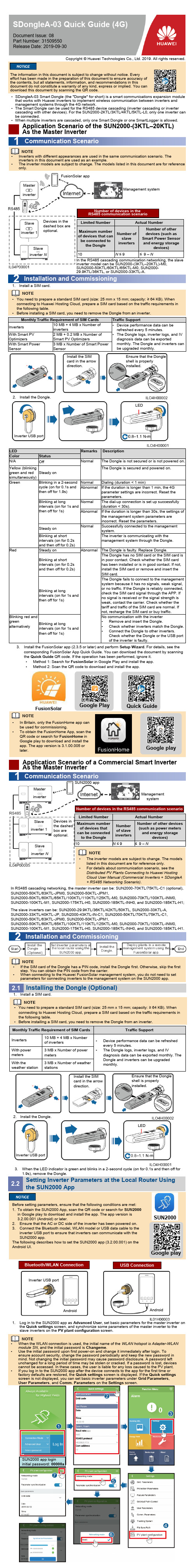
•SDongleA-03 Smart Dongle (the "Dongle" for short) is a smart communications expansion modulethat works with Huawei inverters to implement wireless communication between inverters and management systems through the 4G network.•The Smart Dongle can be used for the RS485 device cascading (inverter cascading or inverter cascading with other devices). For the SUN2000-2KTL/3KTL/4KTL/5KTL-L0, only one inverter can be connected.•When multiple inverters are cascaded, only one Smart Dongle or one SmartLogger is allowed.The information in this document is subject to change without notice. Every effort has been made in the preparation of this document to ensure accuracy of the contents, but all statements, information, and recommendations in thisdocument do not constitute a warranty of any kind, express or implied.You can download this document by scanning the QR code.SDongleA-03 Quick Guide (4G)Document Issue: 08Part Number: 31509550Release Date: 2019-09-301Communication ScenarioApplication Scenario of the SUN2000-(3KTL–20KTL) As the Master Inverter •You need to prepare a standard SIM card (size: 25 mm x 15 mm; capacity: ≥ 64 KB). When connecting to Huawei Hosting Cloud, prepare a SIM card based on the traffic requirements in the following table.•Before installing a SIM card, you need to remove the Dongle from an inverter.2.Install the Dongle.Install the SIMcard in the arrow direction.Ensure that the Dongle shell is properly installed.LED1Communication Scenario2Installation and CommissioningCopyright © Huawei Technologies Co., Ltd. 2019. All rights reserved.NOTE1.Install a SIM card.Monthly Traffic Requirement of SIM CardsTraffic Support Inverters10 MB + 4 MB x Number of inverters •Device performance data can berefreshed every 5 minutes.•The Dongle logs, inverter logs, and IV diagnosis data can be exported monthly. The Dongle and inverters can be upgraded monthly.With Smart PV Optimizers 2 MB + 0.2 MB x Number of Smart PV OptimizersWith Smart Power Sensor 3 MB x Number of Smart PowerSensorInverter USB portNOTE •In Britain, only the FusionHome app can be used for commissioning.•To obtain the FusionHome App, scan the QR code or search for FusionHome in Google play to download and install the app. The app version is 3.1.00.005 or later.Application Scenario of a Commercial Smart Inverter As the Master Inverter 2Installation and CommissioningLED RemarksDescriptionColor Status N/AOffNormalThe Dongle is not secured or is not powered on.Yellow (blinkinggreen and red simultaneously)Steady on The Dongle is secured and powered on.Green Blinking in a 2-second cycle (on for 0.1s and then off for 1.9s)NormalDialing (duration < 1 min)Abnormal If the duration is longer than 1 min, the 4G parameter settings are incorrect. Reset the parameters.Blinking at long intervals (on for 1s and then off for 1s)Normal The dial-up connection is set up successfully (duration < 30s).AbnormalIf the duration is longer than 30s, the settings of the management system parameters are incorrect. Reset the parameters.Steady onNormalSuccessfully connected to the management system.Blinking at short intervals (on for 0.2s and then off for 0.2s)The inverter is communicating with the management system through the Dongle.Red Steady onAbnormalThe Dongle is faulty. Replace Dongle.Blinking at short intervals (on for 0.2s and then off for 0.2s)The Dongle has no SIM card or the SIM card is in poor contact. Check whether the SIM card has been installed or is in good contact. If not, install the SIM card or remove and insert the SIM card.Blinking at longintervals (on for 1s and then off for 1s)The Dongle fails to connect to the management system because it has no signals, weak signal, or no traffic. If the Dongle is reliably connected, check the SIM card signal through the APP. If no signal is received or the signal strength is weak, contact the carrier. Check whether the tariff and traffic of the SIM card are normal. If not, recharge the SIM card or buy traffic.Blinking red and greenalternativelyBlinking at longintervals (on for 1s and then off for 1s)No communication with the inverter •Remove and insert the Dongle.•Check whether inverters match the Dongle.•Connect the Dongle to other inverters.Check whether the Dongle or the USB port of the inverter is faulty.3.Install the FusionSolar app (2.3.5 or later) and perform Setup Wizard . For details, see the corresponding FusionSolar App Quick Guide. You can download the document by scanning the Quick Guide QR code. If the operation has been performed, ignore it. •Method 1: Search for FusionSolar in Google Play and install the app.•Method 2: Scan the QR code to download and install the app.Google playNOTE•If the SIM card of the Dongle has a PIN code, install the Dongle first. Otherwise, skip the first step. You can obtain the PIN code from the carrier.•When connecting to the Huawei FusionSolar management system, you do not need to set parameters for connecting inverters to the management system on the SUN2000 app.Management systemFusionSolar appFusionSolarGoogle Play Master inverterSlave inverter 1Slave inverter NDevices in the dashed box are optional.Number of devices in the RS485 communication scenarioLimited NumberActual NumberMaximum numberof devices that canbe connected tothe DongleNumber ofslaveinvertersNumber of other devices (such as Smart Power Sensor and energy storagedevices)10N ≤9≤9 –NSUN2000 appDevices inthe dashed box are optional.Management systemNumber of devices in the RS485 communication scenarioLimited Number Actual NumberMaximum number of devices that can be connected to the Dongle Numberof slaveinvertersNumber of other devices(such as power metersand energy storagedevices)10N ≤9≤9 –NInstalling the Dongle (Optional)2.1•You need to prepare a standard SIM card (size: 25 mm x 15 mm; capacity: ≥ 64 KB). When connecting to Huawei Hosting Cloud, prepare a SIM card based on the traffic requirements in the following table.•Before installing a SIM card, you need to remove the Dongle from an inverter.1.Install a SIM card.2.Install the Dongle.Inverter USB portInstall the SIM card in the arrow direction.Ensure that the Dongle shell is properly installed.LEDNOTEMonthly Traffic Requirement of SIM Cards Traffic SupportInverters 10 MB + 4 MB x Number of inverters•Device performance data can be refreshed every 5 minutes.•The Dongle logs, inverter logs, and IVdiagnosis data can be exported monthly. The Dongle and inverters can be upgraded monthly.With power meters 3 MB x Number of power metersWith theweather station3 MB x Number of weather stations3.When the LED indicator is green and blinks in a 2-second cycle (on for 0.1s and then off for 1.9s), remove the Dongle.In the RS485 cascading communication networking, the slave inverter model can be SUN2000-(3KTL–20KTL)-M0, SUN2000-50KTL/60KTL/65KTL-M0, SUN2000-29.9KTL/36KTL, or SUN2000-33KTL-A.•Inverters with different appearances are used in the same communication scenario. The inverters in this document are used as an example.•The inverter models are subject to change. The models listed in this document are for reference only.NOTEMaster inverterSlave inverter 1Slave inverter NIn RS485 cascading networking, the master inverter can be: SUN2000-70KTL/75KTL-C1 (optional), SUN2000-50KTL/63KTL-JPM0, SUN2000-50KTL-JPM1,SUN2000-50KTL/60KTL/65KTL/100KTL/110KTL/125KTL-M0, SUN2000-70KTL/100KTL-INM0, SUN2000-100KTL-M1, SUN2000-175KTL-H0, SUN2000-185KTL-INH0, and SUN2000-185KTL-H1;The slave inverters can be: SUN2000-29.9KTL/36KTL/42KTL/50KTL, SUN2000-33KTL-A, SUN2000-33KTL/40KTL-JP, SUN2000-43KTL-IN-C1, SUN2000-50KTL/70KTL/75KTL-C1, SUN2000-50KTL/63KTL-JPM0, SUN2000-50KTL-JPM1,SUN2000-50KTL/60KTL/65KTL/100KTL/110KTL/125KTL-M0, SUN2000-70KTL/100KTL-INM0, SUN2000-100KTL-M1, SUN2000-175KTL-H0, SUN2000-185KTL-INH0, and SUN2000-185KTL-H1.•The inverter models are subject to change. The models listed in this document are for reference only.•For details about communication scenario, see the Distributed PV Plants Connecting to Huawei Hosting Cloud User Manual (Commercial Inverters + SDongleA + RS485 Networking Scenario).NOTE Bluetooth/WLAN Connection USB Connection•When the WLAN connection is used, the initial name of the WLAN hotspot is Adapter-WLAN module SN , and the initial password is Changeme .•Use the initial password upon first power-on and change it immediately after login. To ensure account security, change the password periodically and keep the new password in mind. Not changing the initial password may cause password disclosure. A password left unchanged for a long period of time may be stolen or cracked. If a password is lost, devices cannot be accessed. In these cases, the user is liable for any loss caused to the PV plant.•If you log in to the SUN2000 app after the device connects to the app for the first time or factory defaults are restored, the Quick settings screen is displayed. If the Quick settings screen is not displayed, you can set basic inverter parameters under Grid Parameters , User Parameters , and Comm. Parameters on the Settings screen.NOTESetting Inverter Parameters at the Local Router Using the SUN2000 App2.2Before setting parameters, ensure that the following conditions are met: 1.To obtain the SUN2000 App, scan the QR code or search for SUN2000in Google play to download and install the app. The app version is 3.2.00.001 (Android)or later.2.Ensure that the AC or DC side of the inverter has been powered on.3.Connect the Bluetooth model, WLAN model or USB data cable to theinverter USB port to ensure that inverters can communicate with the SUN2000 app.The following describes how to set the SUN2000 app (3.2.00.001) on the Android UI.SUN2000Google playInverter USB port1.Log in to the SUN2000 app as Advanced User , set basic parameters for the master inverter on the Quick settings screen, and synchronize some parameters of the master inverter to the slave inverters on the PV plant configuration screen.SUN2000 app login initial password: 00000aQuick GuideAndroidAndroid2.Set inverters' Management System and 4G/GPRS parameters.Installation Mode Plug-and-play (applicable to inverters only) IndicatorLEDDimensions (W x H x D)130 mm x 48 mm x 33 mm Net Weight90 g Ingress Protection Rating IP65Typical Power Consumption 3.5 WSIM Card TypeStandard SIM cards (25 mm x 15 mm) Operating Temperature –30ºC to +65ºC Relative Humidity 5% RH to 95% RH Storage Temperature–40ºC to +70ºCSDongleA-03-CNLTE FDD: B1, B3, B8LTE TDD: B39, B40, B41 (38)DC-HSPA+/HSPA+/HSPA/UMTS: B1, B5, B8, B9TD-SCDMA: B34, B39GSM/GPRS/EDGE: 900 MHz, 1800 MHzSDongleA-03-EULTE FDD: B1, B2, B3, B4, B5, B7, B8, B20WCDMA/HSDPA/HSUPA/HSPA+: B1, B2, B5, B8GSM/GPRS/EDGE: 850 MHz, 900 MHz, 1800 MHz, 1900 MHz SDongleA-03-AULTE FDD: B1, B2, B3, B4, B5, B7, B8, B28LTE TDD: B40WCDMA: B1, B2, B5, B8GSM: 850 MHz, 900 MHz, 1800 MHz, 1900 MHz SDongleA-03-JP LTE FDD: B1, B3, B8, B18, B19, B26LTE TDD: B41WCDMA: B1, B6, B8, B19SDongleA-03-KRLTE FDD: B1, B3, B5, B7WCDMA: B1SDongleA-03-CN SRRCSDongleA-03-EU CESDongleA-03-AU Taiwan, China: NCC Australia: RCM SDongleA-03-JP TELEC, JATE SDongleA-03-KRKCWhen connecting inverters to a third-party management system, you need to ensure that the third-party management system supports the standard Modbus TCP protocol and configure the access point table based on the definitions of Huawei inverter interfaces. You need to set NMS server and NMS server port for inverters as required by a third-party management system and replace the client certificate. A third-party management system must comply with the definitions of Huawei inverter interfaces. You need to obtain inverter interface definitions from Huaweitechnical support. This document describes how to connect inverters to a Huawei management system.Installing the Dongle2.3•Before installing the Dongle, you need to remove the Bluetooth module or USB data cable.•Each inverter has only one USB port. When maintaining an inverter locally, you need to remove the Dongle. In this case, the communication between the inverter and the network management system is interrupted. After the local maintenance is complete and the Dongle is installed, the communication is automatically restored.Deploying Plants in a Remote Management System Using the FusionSolar App2.4•Log in to Google Play and search for FusionSolar or scan the QR code to download and install the app. The app version is 2.3.5 or later.•The following describes how to set the FusionSolar app (2.3.5) on the Android UI. Basic ParametersStandard and Frequency BandCertificationPerformance Parameters1.Register a management system account. If a management system account exists, skip this step.•You need to prepare a standard SIM card (size: 25 mm x 15 mm; capacity: ≥ 64 KB). When connecting to Huawei Hosting Cloud, prepare a SIM card based on the traffic requirements in the following table.•Before installing a SIM card, you need to remove the Dongle from an inverter.1.Install a SIM card.2.Install the Dongle.Inverter USB portInstall the SIMcard in the arrow direction.Ensure that the Dongle shell is properly installed.LEDNOTE2.Enter the account and password to log in to the FusionSolar app, and create a plant.Verify the mailbox and activate the account.3.On the Plant tab page, select the corresponding plant to view the device status.NOTEThis section describes how tocreate a site on the FusionSolar. If the inverter is connected to a third-party management system, create a site on the corresponding management system.Monthly Traffic Requirement of SIM CardsTraffic SupportInverters 10 MB + 4 MB x Number ofinverters •Device performance data can be refreshed every 5 minutes.•The Dongle logs, inverter logs, and IV diagnosis data can be exported monthly. The Dongle and inverters can be upgraded monthly.With power meters 3 MB x Number of powermetersWith the weather station 3 MB x Number of weather stationsLED Remarks DescriptionColor Status N/AOffNormal The Dongle is not secured or is not powered on.Yellow (blinking green and red simultaneously)Steady on The Dongle is secured and powered on.Green Blinking in a 2-second cycle (on for 0.1s andthen off for 1.9s)Normal Dialing (duration < 1 min)Abnormal If the duration is longer than 1 min, the 4G/GPRS parameter settings are incorrect. Reset the parameters.Blinking at long intervals (on for 0.1s and then off for 0.1s)Normal The dial-up connection is set up successfully (duration < 30s).Abnormal If the duration is longer than 30s, the settings ofthe management system parameters are incorrect. Reset the parameters.Steady onNormal Successfully connected to the managementsystem.Blinking at short intervals (on for 0.2s and then off for 0.2s)The inverter is communicating with the management system through the Dongle.Red Steady onAbnormal Dongle is faulty. Replace Dongle.Blinking at shortintervals (on for 0.2s and then off for 0.2s)The Dongle has no SIM card or the SIM card is in poor contact. Check whether the SIM card has been installed or is in good contact. If not, install the SIM card or remove and insert the SIM card.Blinking at longintervals (on for 1s and then off for 1s)The Dongle fails to connect to the management system because it has no signals, weak signal, or no traffic. If the Dongle is reliably connected, check the SIM card signal through the APP. If no signal is received or the signal strength is weak, contact the carrier. Check whether the tariff and traffic of the SIM card are normal. If not, recharge the SIM card or buy traffic.Blinking red and greenalternativelyBlinking at longintervals (on for 1s and then off for 1s)No communication with the inverter •Remove and insert the Dongle.•Check whether inverters match the Dongle.•Connect the Dongle to other inverters.Check whether the Dongle or the USB port of the inverter is faulty.FusionSolarGoogle PlayItem Parameter DescriptionParameters for connecting to themanageme nt systemNMS server•Huawei management system: Retain the default value .•Specifies the IP address or website of a third-party management system.NMS server port •Huawei management system: Retain the default value 27250.•Specifies the port number of connecting inverters to a third-party management system.SSL encryption•Set this parameter to (default value) when the device isconnected to Huawei management system.•Set this parameter to or when the device isconnected to a third-party management system. If thisparameter is set to , the data exchange between inverters and the management system is not encrypted, which poses security risks.SIM card parameters (4G/GPRS)APN mode•Set the parameters related to the SIM card. The parameters are obtained from the SIM card carrier.•When APN mode is set to Automatic by default, APN , APNdialup number , APN user name , and APN user password arenot displayed. When APN mode is set to Manual ,APN relatedparameters are displayed. You can set the parameters.Identification typeAPNAPN dialup numberAPN user nameAPN user password PINFAQHow Do I Set Export Limitation Parameters?Set export limitation parameters for the master inverter.•SUN2000-(3KTL–20KTL) as the master inverter: Log in to the FusionSolar app as installer , andchoose Device maintenance > Energy control > Grid-tied point control > Active power to set related parameters.• A commercial smart inverter as the master inverter: Log in to the SUN2000 app as AdvancedUser , and choose Settings > Grid-tied Point Control > Active power control mode to set related parameters.What Should I Do If Slave Inverters Cannot Be Connected In the Cascading Scenario Where aCommercial Smart Inverter Functions as the Master Inverter?•Ensure that the RS485 communications cable is securely connected to the slave inverters.•Log in to the SUN2000 app as Advanced User , choose Settings > Comm. Parameters > RS485, and ensure that the RS485 parameter of the slave inverters is set correctly.•Log in to the SUN2000 app as Advanced User , choose Settings > Comm. Parameters >Management System , and ensure that Cascading channel of the slave inverters is set to .。
深圳汇川技术 IS 360 伺服驱动器 说明书
前言IS360系列伺服驱动器是专门为驱动永磁同步伺服电机(PMSM,Permanent Magnetic Servo Motor)而开发的一款高性能伺服驱动器。
能够实现现代注塑设备伺服油泵控制,亦能实现通用型伺服功能需求。
IS360系列伺服驱动器容量范围宽(额定电流25A~100A),是性能优异的中大功率伺服驱动器。
本手册为IS360系列伺服驱动器的操作指导手册,给使用者提供选型、安装、参数设置、现场调试及故障诊断的相关注意事项及指导。
为正确使用本系列伺服驱动器,请事先认真阅读本手册,并请妥善保存以备后用。
建议设备配套生产厂家将此手册随设备发给最终用户。
开箱验货:在开箱时,请认真确认:1)本机铭牌的型号及伺服驱动器额定值是否与您的订货一致。
箱内含您订购的机器、产品合格证、用户操作手册及保修单。
2)产品在运输过程中是否有破损现象;若发现有某种遗漏或损坏,请速与本公司或您的供货商联系解决。
初次使用:对于初次使用本产品的用户,应先认真阅读本手册。
若对一些功能及性能方面有所疑惑,请咨询我公司的技术支持人员,以获得帮助,对正确使用本产品有利。
由于致力于伺服驱动器的不断改善,因此本公司所提供的资料如有变更,恕不另行通知。
注意!:由于没有按要求操作造成的危险,可能导致中度伤害或轻伤,及设备损坏的情况;请用户在安装、调试和维修本系统时,仔细阅读本章,务必按照本章内容所要求的安全注意事项进行操作。
如出现因违规操作而造成的任何伤害和损失均与本公司无关。
IEC/EN 61800-5-1:2003可调速电气传动系统安规要求;IEC/EN 61800-3:2004可调速电气传动系统;第三部分:产品的电磁兼容性标准及其特定的试验方法。
目录前言 (1)第一章产品信息 (6)1.1 IS360伺服驱动器命名规则 (6)1.2 IS360伺服驱动器系列 (6)1.3 IS360伺服驱动器制动组件选型表 (7)1.4 IS360伺服驱动器外围电气元件选型表 (7)1.5 产品外型及安装尺寸图 (8)第二章接线 (10)2.1 IS360系列伺服驱动器端子分布图 (10)2.2 主回路端子及接线 (10)2.3 控制端子及接线 (11)2.4 IS360伺服驱动器跳线功能说明 (12)2.5 IS360伺服驱动器旋变信号接口端子功能说明(CN6) (12)2.6接线方式 (13)第三章键盘与显示 (16)3.1 本地键盘与显示介绍 (16)3.2 外引键盘与显示介绍 (17)3.3 功能码查看、修改方法说明 (18)第四章伺服油泵调试步骤(针对用户参数表) (20)4.1伺服油泵调试流程图 (20)4.2 电机试运行 (20)4.3 伺服油泵应用调试 (21)4.4自学习补充说明 (22)第五章故障诊断及对策 (24)5.1 故障报警及对策 (24)5.2 常见故障及其处理方法 (34)第六章 ISMG伺服电机使用说明 (36)6.1 ISMG伺服电机命名规则 (36)6.2 ISMG伺服电机规格参数 (36)6.3 ISMG伺服电机外形及安装尺寸图 (41)6.3 ISMG伺服电机基座式安装支撑底板说明 (44)6.4 ISMG伺服电机接线说明 (45)附录1用户参数表 (46)附录2 系统参数表 (50)附录3 伺服电机代码表 (70)1产品信息第一章产品信息1.1 IS360伺服驱动器命名规则伺服驱动器系列1.2 IS3601.3 IS360伺服驱动器制动组件选型表1.4 IS3601.5 产品外型及安装尺寸图IS360T020-C~IS360T100-C外形尺寸及安装尺寸示意图2接线接线 IS360系列伺服驱动器用户手册第二章接线2.1 IS360系列伺服驱动器端子分布图图2-1 伺服驱动器端子分布图2.2 主回路端子及接线IS360系列伺服驱动器用户手册接线控制端子及接线2.3接线 IS360系列伺服驱动器用户手册2.4 IS360伺服驱动器跳线功能说明注:拨码位置指正向接线端子所观察到的位置。
奥迪B8 测量值块功能说明2:-J393(舒适模块)

显示值01 左后中部锁止按钮功能LED(接通/关闭/未安装) 显示值02 右后锁止按钮功能LED(接通/关闭/未安装) 显示值03 左后锁止按钮/后部中央锁止按钮(硬件信号)(已操作/未操作/未安装/不可信) 显示值04 右后锁止按钮(硬件信号)(已操作/未操作/未安装/不可信)
测量值块006 显示值01 驾驶员侧车门旋转锁闩(CAN信号)(车门打开/车门关闭/未安装) 显示值02: 驾驶员侧车门中央门锁内部按钮(CAN信号)(已锁止/已解锁/未安装/不可信) 显示值03 驾驶员侧车门中央门锁状态(CAN信号)(锁止/已解锁/无通信) 显示值04 驾驶员侧车门中央门锁状态(CAN信号)(安全锁定/未安全锁定/无通信/未安装)
奥迪B8 测量值块功能说明:-J393(舒适模块)
地址46
测量值块001 显示值01 端子30 (公差范围8.5 V至15.5 V) 显示值02 端子30 - 2(公差范围8.5-15.5V) 显示值03 端子30 - 3(公差范围8.5-15.5V) 显示值04 CAN信号断路等级 断路等级0 = 用电器无限制 断路等级1 = 用电器部分受限 断路等级2 = 信息娱乐系统关闭,电话关闭 断路等级3 = 许多控制单元不再能够接通 => 许多用于客户的功能不能接通 断路等级4 = 运输模式激活 断路等级7 = 匹配已起动(快速静态电流测量)
测量值块021 显示值01 前一个报警源 0 = 驾驶员侧车门触点 1 = 副驾驶员侧车门触点 2 = 左后车门触点 3 = 右后车门触点 4 = 后舱盖触点 5 = 发动机罩触点 6 = 收音机触点 7 = 挂车 8 = 后窗玻璃破裂 9 = 端子15
10 = 车内监控 11 = 倾斜度传感器 12= 智能报警器 13 = 无授权钥匙 14 = 驾驶员侧车门控制单元 15 = 副驾驶员侧车门控制单元 16 = 左后车门控制单元 17 = 右后车门控制单元 255 = 无已知报警源 显示值02 日期 显示值03 时间 显示值04 未占用
潍柴欧Ⅲ电控发动机CAN总线通讯技术应用规范V1.31
3. 规范适用说明 ................................................................................................... 5
4. 术语解释 ....................................................................................................... 6
版本号 V1.0 V1.1 V1.2 V1.3 V1.31
备注 Dataset:P_532_V46 Dataset:P_532_V46 Dataset:P_532_V46 Dataset:P_532_V46 Dataset:P_532_V46
第 3 页 共 57 页
2. 参考文献
【1】 CAN2.0B 【2】 ISO11898 【3】 SAEJ1939/21-CAN Data Link Layer ,Issue 1994-07,Revised 2006-12 【4】 SAEJ1939/71-CAN Vehicle Application Layer ,Issue 1994-08,Revised 2006-11 【5】 SAEJ1939/3-CAN Application Layer Diagnostics ,Issue 1996-02,Revised 2006-09
5. 节点源地址列表 ................................................................................................. 7
6. 物理层技术条件 ................................................................................................. 8
- 1、下载文档前请自行甄别文档内容的完整性,平台不提供额外的编辑、内容补充、找答案等附加服务。
- 2、"仅部分预览"的文档,不可在线预览部分如存在完整性等问题,可反馈申请退款(可完整预览的文档不适用该条件!)。
- 3、如文档侵犯您的权益,请联系客服反馈,我们会尽快为您处理(人工客服工作时间:9:00-18:30)。
2.2.1.2 Can.h..........................................................................................................................2
2.2.2 配置文件 ...........................................................................................................................2
2.3.2.3 Can_DisableControllerInterrupts ...............................................................................4
2.3.2.4 Can_EnableControllerInterrupts ................................................................................5
2.3.2.7 Can_GetVersionInfo ..................................................................................................6
2.3.3 影响某个 HOH 的函数.....................................................................................................7
1.5
术语和缩写 ...............................................................................................................................1
2 CAN Driver 模块 ......................................................................................................................................2
2.4.1.1 CAN_USED_CONTROLLER_NUM .....................................................................10
2.3.5.1 CAN_PHYx_MB_ISR....................................................................9
2.3.5.2 CAN_PHYx_Busoff_ISR ........................................................................................10
2.3.4.2 Can_MainFunction_Read ..........................................................................................8
2.3.4.3 Can_MainFunction_BusOff.......................................................................................8
2.3.4 需要周期调用的函数 .......................................................................................................8
2.3.4.1 Can_MainFunction_Write .........................................................................................8
1.3
读者对象 ...................................................................................................................................1
1.4
参考文档 ...................................................................................................................................1
2.3.2.5 Can_DisableGlobalInterrupt ......................................................................................5
2.3.2.6 Can_EnableGlobalInterrupt .......................................................................................6
2.3.1.1 Can_Init .....................................................................................................................3
2.3.2 影响某个 CAN Controller 的函数....................................................................................3
2.3
接口函数使用说明 ...................................................................................................................3
2.3.1 影响整个 CAN hardware unit 的函数 ..............................................................................3
1.1
目的 ...........................................................................................................................................1
1.2
适用范围 ...................................................................................................................................1
2.2.1 内核文件 ...........................................................................................................................2
2.2.1.1 Can.c ..........................................................................................................................2
CAN Driver 模块
软件使用说明文档
恒润科技
所有权声明
该文档及其所含信息是恒润科技有限公司的财产。该文档及其所含信息的复制、使用及披 露必须得到恒润科技有限公司的书面授权。
第I页
目录
1 文档介绍 ...................................................................................................................................................1
2.4
配置参数使用说明 .................................................................................................................10
2.4.1 配置 CAN 通道...............................................................................................................10
2.3.4.4 Can_MainFunction_Mode .........................................................................................9
2.3.5 中断服务函数 ...................................................................................................................9
2.3.3.1 Can_Write ..................................................................................................................7