LPCVD 多晶硅的形貌和结构的研究
lpcvd多晶硅生产工艺流程
lpcvd多晶硅生产工艺流程英文回答:Low-Pressure Chemical Vapor Deposition (LPCVD) Polysilicon Fabrication Process.LPCVD is a thin-film deposition technique used tocreate polycrystalline silicon (polysilicon) layers on semiconductor substrates. The process involves the chemical reaction of silane gas (SiH4) with oxygen in a vacuum chamber at low pressure. The following is an overview ofthe LPCVD polysilicon production process:1. Substrate Preparation: The substrate, typically a silicon wafer, is cleaned to remove any contaminants. Athin layer of silicon dioxide (SiO2) may be deposited onthe substrate to improve adhesion and prevent contamination.2. LPCVD Reactor: The substrate is placed in an LPCVD reactor, which is a vacuum chamber equipped with gas inlets,a heater, and a gas exhaust.3. Gas Introduction: Silane gas (SiH4) and oxygen (O2) are introduced into the reactor. The flow rates of these gases are carefully controlled to achieve the desired stoichiometry of the polysilicon film.4. Chemical Reaction: Inside the reactor, the silane and oxygen gases react to form silicon atoms and hydrogen gas according to the following chemical equation: SiH4 + O2 → Si + 2H2.5. Film Deposition: The silicon atoms condense on the substrate surface, forming a polycrystalline silicon film. The thickness and properties of the polysilicon film are controlled by the deposition time, temperature, and gas flow rates.6. Post-Deposition Treatment: After deposition, the polysilicon film may undergo additional processing steps, such as annealing or doping, to improve its electrical and physical properties.中文回答:LPCVD多晶硅生产工艺流程。
6.LPCVD
清洗流量计(N2)
工艺开始执行至结束
调压(N2, NH3, O2)
抽流量计
抽本体真空
清洗流量计(N2)
抽流量计
回填(N2)
2、Exercises-设备操作流程
9、打开炉门, 小心取出硅片, 关上炉门 10、抽真空 11、停止加热 12、关工艺气体(TEOS源)
(足够高真空以后) 13、关罗兹泵 14、关机械泵 15、关主机 16、关加热电源 17、关主电源 18、关冷却水、压缩空气
1、Fundamentals-薄膜质量评价
晶粒(大小、晶向等)
与淀积温度、掺杂类型、热处理工艺有很大关系 温度对多晶硅晶粒的影响: <590℃,无定形态 >610℃,晶体态 590~610℃,中间态
晶粒大小对表面粗糙度的影响:
1、Fundamentals-薄膜质量评价
应力与应力梯度
应力:拉应力、压应力 来源、影响、测量、控制
热偶报警
表示控制系统的零点跳动大
超温报警(系统自动转到保温状态) TEOS源液位报警 表示炉膛温度超过极限超温报警值(系统将自动关掉炉子的加 热电源)
TEOS源温度报警 压力差报警(当实际压力值与设定值之差超过某一固定值时)
F3: * 表示故障;- 表示正常
1、Fundamentals-薄膜淀积之LPCVD
氧化硅薄膜(Silicon dioxide)
1、Fundamentals-薄膜淀积之LPCVD
氮化硅薄膜(Silicon Nitride)
用途:电气/热绝缘层、钝化层、掩膜层、刻蚀阻止层 反应方程式:
3SiH4 + 4NH3 -> Si3N4 + 12H2 x SiCl2H2 + y NH3 -> SixNy + 2xHCl + 3y/2H2
LPCVD制备微晶硅薄膜及热处理工艺研究
LPCVD制备微晶硅薄膜及热处理工艺袁媛(哈尔滨工业大学材料科学与工程学院,哈尔滨150001)摘要:试验采用低压化学气相沉积(LPCVD)方法在单抛n型(100)4寸硅片上沉积微晶硅薄膜,沉积薄膜前用湿氧氧化法在硅片表面氧化SiO2层作为扩散阻挡层。
用普通氧化铝管式炉加热处理制成的微晶硅薄膜制备多晶硅薄膜。
选取了650℃、800℃、950℃及1100℃不同退火温度,炉内通入高纯Ar气,退火时间2小时。
用Raman光谱和XRD测试薄膜的二次晶化状态,用SEM分析薄膜的表面形貌。
关键词:低压化学气相沉积;多晶硅薄膜;退货温度1 引言多晶硅薄膜是综合了晶体硅材料和非晶硅合金薄膜的优点,在能源科学、信息科学的微电子技术中有着广泛应用的一种新型功能薄膜材料[1]。
LPCVD方法生长多晶硅薄膜内含高密度的微孪晶,生成的晶粒尺寸小,载流子迁移速率较低,因此在器件应用方面受到了限制。
为了使制备的多晶硅薄膜具有较大的晶粒尺寸以及较高的载流子迁移率,我们采用普通氧化铝管式炉加热处理制成的微晶硅薄膜,使其二次晶化,研究退火温度对多晶硅薄膜的影响。
2 分析2.1 薄膜晶化率与晶粒尺寸分析图2-1为在597℃条件下沉积的薄膜样品,分别在650℃、800℃、950℃、1100℃温度下退火2小时后的Raman光谱图。
在Raman谱图中,480cm-1处代表非晶硅散射峰,520cm-1处代表多晶硅散射峰。
一般而言,Raman特征峰越强,半高宽越小,峰形越对称,材料的结晶性越好;散射峰越靠近单晶硅峰位521.5cm-1,薄膜的晶粒尺寸越大。
从图2-1可以看出,随着退火温度升高,曲线在520cm-1处散射峰强度逐渐升高且越来越尖锐,480cm-1处散射峰基本消失。
这表明,从未退火的样品a),到退火后的样品b)~e),薄膜样品中非晶成分随着退火温度的增加而减少,多晶成分逐渐增多,多晶硅薄膜晶化率提高。
且退火温度由650℃升高至1100℃的过程中,Raman 散射峰位由519.067cm -1向右移至520.597cm -1处,逐渐靠近单晶硅散射峰,说明退火后硅薄膜中的晶粒尺寸随退火温度的升高而长大。
6第六章 化学气相淀积
教师: 潘国峰 E-mail: pgf@
河北工业大学微电子研究所
化学气相淀积:是指一种或数种物质的气体,以某种方式 激活后,在衬底发生化学反应,并淀积出所需固体薄膜的 生长技术。其英文原名为 “Chemical Vapour Deposition”,简称为 “CVD”。 ULSI中常用“CVD” 制备各种薄膜。
2.低压化学气相淀积
低压化学汽相淀积(LPCVD)反应器的结构示意图
应用情况
多晶硅:SiH4/Ar(He) Si3N4: SiH2Cl2 +NH3 PSG: SiH4 +PH3 +O2 BSG: B2H6 +O2 SiO2: SiH2Cl2 +NO2 620℃ 750-800℃ 450℃ 450℃ 910℃
Si(OC2H5)4
650~750
SiO2 +副产品
3. SiO2薄膜性质
6.3.2 多晶硅薄膜
1.多晶硅淀积动力学 A.反应方程式 SiH4 Si+2H2 由N2或Ar携带SiH4 20%+ N2 80% B.淀积参量:压力、温度、硅烷浓度、杂质浓度
温度:600℃~650℃ ,一般用625℃
化学反应主要是吸附和分解:
SiH4(g)SiH2(g)+H2(g) SiH2(g)+Si(s)2(Si(s)-H*) (式二)吸附 (式三)分解
2(Si-H*)2Si(s)+H2(g)
(式四)淀积
(式三)表示吸附,(式四)表示分解。其中g,s分别表示 气态和固态。在充分吸附的情况下,(式二)和(式三)处于平 衡状态下,而(式四)即(Si-H*)的热分解过程将决定淀积率。 当衬底温度一定时,即分解率一定时,淀积率将直接与吸附 反应剂分子的多少有关。
PECVD法制备多晶硅薄膜
• •
• •
2.2多晶硅薄膜太阳能电池 多晶硅薄膜太阳电池因同时具有单晶硅的高迁移率,长寿命及非晶硅材料成 本低、可大面积制备,材料制备工艺相对简单的优点,且无光致衰减效应。多 晶硅薄膜电池技术可望使太阳电池组件的成本得到更大程度的降低,从而使得 光伏发电的成本能够与常规能源相竞争
•
目前认为,影响多晶硅薄膜太阳能电池性能的主要因素是晶粒尺寸,晶界宽 度和有害杂质的含量及分布方式。此外影响电池光电转换效率的因素还有: 禁带宽度,温度,载流子的复合寿命,光强,参杂浓度及剖面分布,表面复 合速率以及衬底因素等 纳米多晶硅薄膜太阳能电池基于纳米尺寸的多晶硅薄膜,当晶粒尺寸为几个 纳米时,会产生量子特性,其导电不再是由热电子引起,而是由量子隧穿效 应代替。纳米多晶硅薄膜太阳能电池可以在廉价衬底上制备,且无效率衰减 问题,转化效率比非晶硅薄膜太阳能电池高,成本低,所以具有市场发展潜 力。 2.3GaAs太阳能电池 GaAs具有直接能带隙,宽度1.42eV。实验室最高效率已达到24%以上。砷化 镓太阳电池目前大多用液相外延方法或金属有机化学气相沉积技术制备,因 此成本高,产量受到限制。砷化嫁太阳电池目前主要用在航天器上。
•
多晶硅薄膜的制备方法
• 生长多晶硅薄膜的方法很多,这些方法从两个方面来分类,一种分类是按照 制备温度的高低,可以分为高温制备技术(>600℃)和低温制备技术(<600℃)。 另一种分类是按照制备过程,可分为直接制备方法和间接制备方法,主要有 以下六种 : 一 化学气相沉积法(CVD)、二 液相外延技术(LPE)、三 固相晶化法 (SPC)、四 金属诱导晶化(MIC)、五 区域熔化再结晶法(ZMR)、六 激光晶化法(LIC)。
直接法就是通过不同的反应条件以控制最初晶粒的形成并直接长大在基片衬 底上制备多晶硅的方法。 一 化学气相沉积法(CVD)
lpcvd原位掺杂多晶硅探究
lpcvd原位掺杂多晶硅探究英文回答:LPCVD (Low Pressure Chemical Vapor Deposition) is a widely used technique for depositing thin films of materials, including polysilicon. In LPCVD, a precursor gas is introduced into a chamber at low pressure and high temperature, where it decomposes and deposits the desired material onto a substrate.One interesting aspect of LPCVD is the ability to perform in-situ doping of the deposited material. This means that during the deposition process, impurities can be intentionally introduced into the growing film to alter its electrical properties. In the case of polysilicon, this can be achieved by adding dopant gases such as phosphine or diborane to the precursor gas.The doping process in LPCVD is controlled by adjusting the flow rate and concentration of the dopant gases. Theimpurities are incorporated into the growing film by diffusion, resulting in a modified material with altered conductivity. This is particularly useful in thefabrication of microelectronic devices, where different regions of the device may require different electrical characteristics.For example, let's say we want to create a polysilicon resistor with a specific resistance value. By adjusting the flow rate of the dopant gas, we can control the concentration of dopants in the film and thus theresistivity of the material. This allows us to tailor the electrical properties of the resistor to meet our design requirements.中文回答:LPCVD(低压化学气相沉积)是一种广泛应用于薄膜沉积的技术,包括多晶硅。
(太阳能光伏)多晶硅薄膜的制备方法
多晶硅薄膜的制备方法多晶硅薄膜材料同时具有单晶硅材料的高迁移率及非晶硅材料的可大面积、低成本制备的优点。
因此,对于多晶硅薄膜材料的研究越来越引起人们的关注,多晶硅薄膜的制备工艺可分为两大类:一类是高温工艺,制备过程中温度高于600℃,衬底使用昂贵的石英,但制备工艺较简单。
另一类是低温工艺,整个加工工艺温度低于600℃,可用廉价玻璃作衬底,因此可以大面积制作,但是制备工艺较复杂。
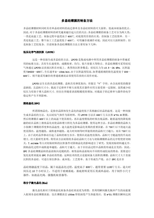
目前制备多晶硅薄膜的方法主要有如下几种:低压化学气相沉积(LPCVD)这是一种直接生成多晶硅的方法。
LPCVD是集成电路中所用多晶硅薄膜的制备中普遍采用的标准方法,具有生长速度快,成膜致密、均匀、装片容量大等特点。
多晶硅薄膜可采用硅烷气体通过LPCVD法直接沉积在衬底上,典型的沉积参数是:硅烷压力为13.3~26.6Pa,沉积温度Td=580~630℃,生长速率5~10nm/min。
由于沉积温度较高,如普通玻璃的软化温度处于500~600℃,则不能采用廉价的普通玻璃而必须使用昂贵的石英作衬底。
LPCVD法生长的多晶硅薄膜,晶粒具有择优取向,形貌呈“V”字形,内含高密度的微挛晶缺陷,且晶粒尺寸小,载流子迁移率不够大而使其在器件应用方面受到一定限制。
虽然减少硅烷压力有助于增大晶粒尺寸,但往往伴随着表面粗糙度的增加,对载流子的迁移率与器件的电学稳定性产生不利影响。
固相晶化(SPC)所谓固相晶化,是指非晶固体发生晶化的温度低于其熔融后结晶的温度。
这是一种间接生成多晶硅的方法,先以硅烷气体作为原材料,用LPCVD方法在550℃左右沉积a-Si:H薄膜,然后将薄膜在600℃以上的高温下使其熔化,再在温度稍低的时候出现晶核,随着温度的降低熔融的硅在晶核上继续晶化而使晶粒增大转化为多晶硅薄膜。
使用这种方法,多晶硅薄膜的晶粒大小依赖于薄膜的厚度和结晶温度。
退火温度是影响晶化效果的重要因素,在700℃以下的退火温度范围内,温度越低,成核速率越低,退火时间相等时所能得到的晶粒尺寸越大;而在700℃以上,由于此时晶界移动引起了晶粒的相互吞并,使得在此温度范围内,晶粒尺寸随温度的升高而增大。
pecvd法低温沉积多晶硅薄膜的研究
pecvd法低温沉积多晶硅薄膜的研究多晶硅(PolycrystallineSilicon,简称多晶Si)是由多个晶格交错排列而成的硅材料,具有高电导率、热导率、弹性模量和抗冲击强度的特点,在电子元器件中具有广泛的应用前景。
传统的多晶Si 薄膜沉积过程是在温度高于1000℃的环境中,由DC/RF源进行等离子体化学气相沉积(Plasma-Enhanced Chemical Vapor Deposition, PECVD)而产生。
沉积温度较高,会引起材料表面的组分失衡,以及因温度过高导致发生拉伸应力等等,这些因素会严重影响薄膜的性能,降低工作效率。
因此,低温沉积多晶硅薄膜成为当前研究的热点话题,PECVD法低温沉积多晶硅薄膜的研究也引起了研究者的广泛关注。
关于PECVD法低温沉积多晶硅薄膜PECVD法低温沉积多晶硅薄膜的研究的核心点在于在低温下(较常规高温沉积温度低几百度)成功沉积出低拉伸应力、组分均衡、较高饱和电导率以及较好的传输特性的多晶硅薄膜。
研究者们采用半导体工艺(如PECVD、CVD和DLCVD)、化学法(如LPCVD)以及外来离子辅助沉积(ILCVD)等多种方法对低温多晶硅薄膜进行沉积,并研究其相关的性能,取得了积极的成果。
关于PECVD法低温沉积多晶硅薄膜的研究进展由于低温沉积多晶硅薄膜有较高的抗压强度和热稳定性,因此越来越多的应用被发现,如MEMS(微机电系统)、电晶体管和半导体光刻机等。
根据研究人员的不断发展,PECVD法低温沉积多晶硅薄膜也取得了较好的进展,如实现了低温多晶硅薄膜的气体态沉积;发展出更多的多晶硅气相沉积化学体系,如用于高性能MEMS的气相铝型化学体系;成功制备出多晶硅薄膜,可保证在低拉伸应力情况下,满足电子元器件的表征要求;以及发现新的半导体工艺,提高沉积速率,能够保持良好的构筑效率等。
关于PECVD法低温沉积多晶硅薄膜的应用PECVD法低温沉积多晶硅薄膜的应用主要体现在电子元器件的表征要求满足以及获得的优异的性能表现上。
- 1、下载文档前请自行甄别文档内容的完整性,平台不提供额外的编辑、内容补充、找答案等附加服务。
- 2、"仅部分预览"的文档,不可在线预览部分如存在完整性等问题,可反馈申请退款(可完整预览的文档不适用该条件!)。
- 3、如文档侵犯您的权益,请联系客服反馈,我们会尽快为您处理(人工客服工作时间:9:00-18:30)。
(1)
6279
where lhk t and 11 1 1 are intensities o f ( h k l ) and (1 1 1) planes, respectively. Film morphology and microstructure were investigated using plane and crosssectional scanning electron microscopy (SEM) and transmission electron microscopy (TEM). 10 2
1. Introduction
Polycrystalline silicon (polysilicon) films formed by low-pressure chemical vapour deposition (LPCVD) of silane (Sill4) are widely used in integrated circuits for various applications as MOS gates, interconnects, resistors, and emitter contacts. Other applications include photovoltaic conversion, thermal and mechanical sensors, and thin film transistors (TFT) for large-area liquid-crystal displays (LCDs). The electrical performance of the polysilicon is strongly determined by its microstructure, which depends on deposition parameters [1-4]. Electrical properties for as-deposited polycrystalline or as-deposited amorphous silicon have been investigated by a number of authors [5,7]. It was suggested that deposition temperature should be as low as possible to obtain high conductivity and carrier mobility. It is well known that the surface roughness of polysilicon degrades the electrical characteristics of dielectric film on the polysilicon [6, 8, 9]. However, in order to obtain the sufficient storage capacitance required for 64M bit dynamic random access memory (DRAM) and beyond, some fabrication technologies having an uneven surface of hemispherically grained (HSG) polysilicon film have been suggested for increasing effective surface area [10, 11]. In the present work, we investigated the deposition condition dependence of surface morphology and microstructure of LPCVD polysilicon. The grain growth mechanism during the deposition and subsequent in situ annealing at the amorphous to crystal0022-2461 9 1993 Chapman & Hall
Fig. 1 shows the Arrhenius plots of growth rates in the temperature range 540-640~ under 0.25 torr. The silane growth is controlled by surface reaction and has an apparent activation energy of 34 kcal mol - 1, which agrees well with 32-39.9kcalmo1-1 reported by Harbeke et al. I-4]. The surface morphology of the films at various deposition temperatures is shown in Fig. 2. It was observed that the film deposited at 560 ~ has a smooth surface and the film deposited at 570~ has some nuclei, which start to grow in the amorphous phase. The film deposited at 580~ has hemispherical grains (HSG), while at 590-600 ~ it has an extra-rough, rugged surface with a greater surface profile variation, and at 620 ~ has a rough surface. The surface morphologies of the specimens annealed at 1000 ~ for 4 h were similar to those of asdeposited specimens. These facts imply that the surface morphology of the film is strongly dependent on the deposition temperature, but is almost independent of annealing conditions. Crystal structures of the films were analysed using XRD. Three X-ray diffraction peaks showing (1 1 1), (1 1 0),, and (3 1 1) reflections were detected for the samples deposited at and above 570 ~ Fig. 3 shows the ratios of(1 1 0) and (3 1 1) intensity to (1 1 1) intensity as a function of deposition temperature. For a
line transition temperature without breaking the vacuum has been also discussed.
2. Experimental procedure
The experiments were carried out in an inductionheated hot-wall horizontal reactor. Undiluted monosilane (Sill4) gas as a silicon source was supplied from both sides of the tube and was evacuated using a rotary pump. The deposition parameter, temperature and pressure, were varied within the constraints of equipment available and film quality. The starting wafers were CZ(1 0 0) p-type silicon, with 100 nm thick silicon dioxide (SiO2). The film thickness was measured using an e!lipsometer, and was approximately 100 nm unless otherwise specified. All films were undoped and were visually inspected with an oblique light and a qualitative assessment of film quality based on the hazy spot. The preferred orientation (texture) of the films was investigated using an X-ray diffractometer (XRD) with a glancing incident angle to reduce the penetration depth of X-rays and hence the diffraction from the suhstrate silicon. The texture of the films was measured by comparing the intensity of diffraction peaks with those obtained on randomly oriented polycrystalline film. In order to quantify the texture of the films, the relative unit (r.uh k Z) for each diffraction plane (h k l) is normalized to the (! 1 1) plane as follows.