Trimble MMS车载扫描系统介绍
常用三维移动扫描车型号及参数(精)

常用三维移动扫描车型号及参数三维移动扫描车型号1:拓普康IP-S2移动测量系统仪器介绍:拓普康IP-S2移动测量系统成功解决了多维空间信息采集的瓶颈,采用卫星定位、惯导测量等融合定位方式,利用集成的360°相机和多重激光扫描设备,可以快速地提供精确的多元数据流,并且可在线进行数据更新,节省了大量的人力物力。
目前,在全球已有近千套IP-S2移动测量系统成功服务于城市景观漫游(如三维数字街景数据采集)、道路及管线设施普查、公众安全等领域。
产品特点:● 精确记录具有空间参照信息和时标信息的RGB点云及视频影像● 高精度GPS+GLONASS信号跟踪● 惯性测量单元辅助导航定位● 获取道路及周边地物的3D特征● 获取道路沿线360°全景影像● 快速、简易的安装和拆卸特性说明:可同时获取具有空间和时标信息的RGB点云及360°影像双频GPS+GLONASS 定位IP-S2主控单元使用多传感器实时获取精确的车辆位置和姿态。
由于双频GNSS接收机能同时跟踪GPS和GLONASS信号,从而使IP-S2应用范围更广,尤其在有遮挡的城市区域。
内置IMU连续不间断的监控车辆的运动和姿态,即使行驶在有障碍物、隧道等没有GNSS信号的情况下,IP-S2系统也能跟踪定位车辆的位置。
车轮编码器车轮编码器提高了定位精度和可靠性。
安装在后轮的车轴上,编码器可以检测每个轮子的转动。
车辆姿态是通过比较两轮之间的转动速度而精确计算得到。
激光扫描仪(可选)三个2D激光扫描仪能够获取道路路面及两侧的高分辨率3D点云,并且不受光线条件的影响。
IP-S2系统利用高精度的点云数据和GPS时间能够定期进行道路形状、位置和属性等的检测。
360°全景相机(可选)360°全景相机连续捕获球面影像。
影像与点云的完美结合大大提高了三维分析功能。
高度集成的安装支架,易于快速安装和拆卸IP-S2的安装支架将所有的传感器集成到一块,易于快速、简易安装和拆卸。
常用三维移动扫描车型号及参数3(精)
常用三维移动扫描车型号及参数2
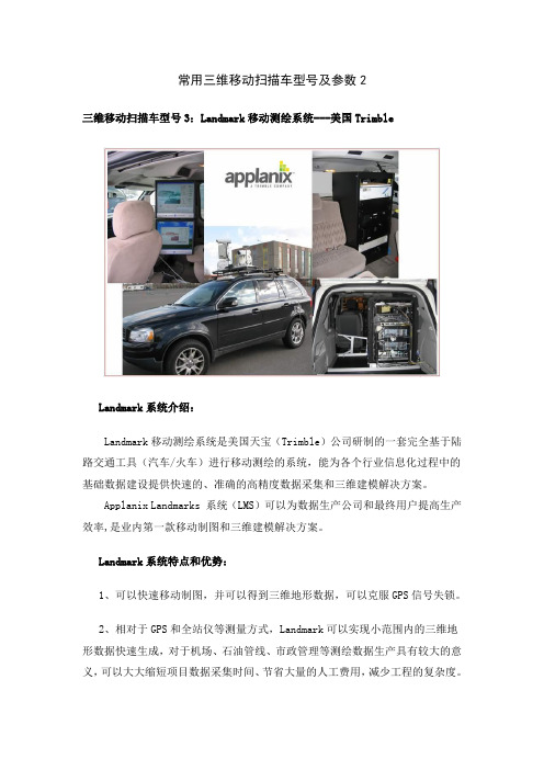
三维移动扫描车型号3:Landmark移动测绘系统---美国Trimble
Landmark系统介绍:
Landmark移动测绘系统是美国天宝(Trimble)公司研制的一套完全基于陆路交通工具(汽车/火车)进行移动测绘的系统,能为各个行业信息化过程中的基础数据建设提供快速的、准确的高精度数据采集和三维建模解决方案。
Applanix Landmarks 系统(LMS)可以为数据生产公司和最终用户提高生产效率,是业内第一款移动制图和三维建模解决方案。
Landmark系统特点和优势:
1、可以快速移动制图,并可以得到三维地形数据,可以克服GPS信号失锁。
2、相对于GPS和全站仪等测量方式,Landmark可以实现小范围内的三维地形数据快速生成,对于机场、石油管线、市政管理等测绘数据生产具有较大的意义,可以大大缩短项目数据采集时间、节省大量的人工费用,减少工程的复杂度。
3、相对于航空摄影测量方式,机动灵活,成本低,更新数据快,周期短。
4、系统平台可以搭载多种遥感数据获取系统。
5、获取数据快速精准,并且信息量非常大。
Landmark系统技术参数:
1. 定位定姿系统(POS LV)
2. 数码相机
3.激光扫描仪-SICK。
Trimble Scene三维激光扫描仪操作流程

目录1 概述 (2)2 外业数据采集 (2)2.1 外业踏勘 (2)2.2 控制点数据 (2)2.3 点云数据 (10)3 内业软件简介 (10)3.1 TRIMBLE Scene的组成 (11)3.2 快速视图 (12)3.3 平面视图 (13)3.4 3D立体显示 (14)3.5 快捷图标说明 (14)3.6 点云数据导出 (16)3.7 测量距离 (17)4 内业数据处理流程 (17)4.1 数据整理 (17)4.2 加载数据 (18)4.3 选择参考点、面 (18)4.4 靶球、面配对拼接 (19)4.5 应用彩色点云 (21)4.6 导出点云建立模型 (21)1 概述随着测绘技术的日益发展,高效,简便的各项技术相继问世。
TRIMBLE三维激光扫描仪为当前世界最小、最轻的激光扫描仪。
与传统的二维平面图相比,任何人都会发现三维图像的优点。
因为激光扫描仪可以在每秒得到约百万测量点,并产生其周围环境的精确三维图像。
TRIMBLE三维扫描仪尺寸为24x20x10 C㎡重量:5kg采用集成彩色相机,7000w像素的无视差彩色相机高性能电池可持续工作5小时数据管理采用便携带的SD卡测量速度为976000点/秒误差±2mm视野305°(垂直)x 360°(水平)数据处理流程分为:外业激光数据采集、内业激光数据拼接、后期三维建模、数据集成系统。
2 外业数据采集2.1 外业踏勘每个项目开始之前,必须对需要采集数据的地点进行踏勘,对其周围的地理环境、天气因素、人为影响作一个系统的了解,做好计划,并防止采集数据发生的意外。
2.2 控制点数据为了对扫描图像进行绝对定向,需在整个房屋附近设置多个靶球或靶点,并利用仪器,测量出每一个点的位置。
靶球放置必须保证前后站都能看到。
放置好靶球后,架起仪器开机。
开机后界面如下:仪器为触摸屏操作,点击管理选项,进入管理对话框,在项目里建好此次扫描的项目文件,并命名。
车载激光扫描仪完成京津塘路面测量任务

车载激光扫描仪完成京津塘路面测量任务
8月18日,测绘分院首次利用美国Trimble公司的MX8 车载移动激光扫描测量系统完成了京津塘高速项目23公里5m间距的精细化路面测量。
图1.Trimble MX8车载激光扫描扫描测量系统
图2.Trimble MX8车载激光扫描扫描测量系统
由于是现有道路改建项目,进行常规的测量作业要上高速公路,一是需向公
路路政高速处和高速交警大队分别申请上路作业许可,二是京津塘高速车流量大,人工测量安全风险突出。
而车载移动激光扫描技术集成了高精度的激光扫描仪(Riegl)、全球定位系统(GPS)、惯性测量系统(IMU)及车轮编码系统(DMI),仅用两天时间就完成了全部外业数据的自动化采集工作(传统测量模式至少需半个月)。
相关成果如下:
图3.激光点云数据
图4. 激光点云数据
图5. 激光点云数据
图6. 实时获取与点云数据匹配的影像
三维激光扫描技术是继GPS之后,测绘行业在技术上的又一次飞跃。
历经十几年的发展,三维激光扫描技术无论是在硬件设施上,还是在应用领域上,都在快速不断的向前发展。
如今,三维激光扫描技术已经成为空间数据获取的重要技术手段,使我们从传统的人工单点数据获取变为连续自动数据获取,不仅提高了观测的精度和速度,而且使数据的获取和处理朝智能化和自动化方向发展。
由于测量任务内容和经费限制,我们仅利用以上数据生成了设计所需的23
公里5m间距的断面数据,如下图:
图7. 激光点云数据生成的5m间距断面数据
经检核确认,此次利用激光扫描技术生成的断面成果很好地满足了项目需求。
测绘分院
2013年8月23日。
trimble 中文简易使用手册版本5p

单击确定即可,可以看到在卫星图标的旁边出现图标,此图标会不断的闪动——等待改正信号的获得
2.4 数据采集(可选参考)
新建文件
在数据区域中点击子区中的新建文件
文件名:在此输入数据文件名称。 词典名:通过下拉键选择
已经事先编辑好的数据词典。数据字典可以很好的方便用户完成外业采集的工作。如:在采集不同地点不同树种的工作中,到达地点之后可以直接从列表中选择事先设置好的树木的种类,而不需您一遍又一遍的输入,提高工作效率。 其他默认 点击创建,提示输入天线高
1.3重新设置
当设备出现死机、屏幕没有响应、屏幕不灵敏不能和电脑同步等问题时可以通过重新设置来解决。如果恢复了出厂设置问题还是得不到解决请与北京维修部联系。
软启动:按重设键(数据和已装软件不会丢失)
提示:当取出电池几分钟后,设备将自动执行软启动,此时开机需要按住电源键1-4秒。
硬启动:同时按重设键+电源键(没保存的数据会丢失)
Pathfinder office软件是Trimble导航公司MGIS产品数据采集后处理软件,可以处理实时差分和后差分数据。本软件不带软件狗,用户可自由使用。
3.1软件的安装
Pathfinder office软件最新版本
第一:运行安装文件的中的setup.exe文件,根据其提示进行软件的安装。
第二:输入软件的安装码(请查看SN文件)
2、连接汽车点烟器,通过汽车充电
用交流变压器和国际通用转接器给掌上接收充电,一般4个小时左右即可完成充电。
注意:用USB电缆将掌上接收机连接到计算机,将不会给掌上接收机电池充电。
电源LED灯状态:
·电压过低时,LED指示灯变成红色并闪烁。
·正在充电时,LED指示灯变成绿色并闪烁。
美国天宝三维激光扫描仪简介-Trimble CX_DS_CN

2M3(扫描仪在仪器箱内) 湿度 : 20% ~ 85%, 非冷凝大气 标准配件 . . . . . . . . . . . . . . . . . . . . . . . . . . . . . . . . . . . . . . . . . . . . 滚动仪器箱;
集成供电单元 ; Trimble基座 ; 50贴片 ; USB闪存;
修; • 通过填写表格和容积测量来校准储油罐体积。
全面解决方案 Trimble CX 数据可单独使用,也可与Trimble 其他测量数据联合使用,例如 Trimble FX™ 、 GX™ 3D扫描仪和 Trimble VX™ 空间测站仪。
Trimble Cx 扫描仪
性能指标
脉冲波 ™ . . . . . . . . . . . . . . . . . . . . . . . . . . . . . . . . . . . . . . . 脉冲与相位相结合 测程(标准条件下)1,2 . . . . . . . . . . . . . . . . . . . . . . . . . . . . . . 80m(90%反射表面)3
数据传输线 , WLAN天线 可选配件 . . . . . . . . . . . . . . . . . . . . . . . . . . . . . . . . . . . . . . . . . .Trimble Tablet
Trimble TX8扫描仪介绍
trimble tx8 Laser scanner
Key Features
Increase field productivity with less scans and number of stations
The Trimble® TX8 laser scanner sets new standards for performance and ease of use in high-speed collection of 3D data. Using a state-of-the-art blend of speed, long range and precision, the Trimble TX8 delivers high quality results in industrial measurement, engineering, construction, forensics and other applications that require high levels of accuracy and flexibility.
DATASHEET
trimble tx8 laser scanner
Performance
Overview
physical
Dimensions. . . . . . . . . . . . . . . . . . . . . . . . . . . 335 mm W x 386 mm H x 242 mm D (13.2 in W x 15.2 in H x 9.5 in D) Weight. . . . . . . . . . . . . . . . . . . . . . . . 10.6 kg (23.3 lb) with tribrach and no battery; 11.0 kg (24.3 lb) with tribrach and battery Power supply . . . . . . . . . . . . . . . . . . . . . . . . . . . 76 mm W x 43 mm H x 130 mm D (3.0 in W x 1.7 in H x 5.1 in D); Weight: 0.66 kg (1.46 lb) Power consumption. . . . . . . . . . . . . . . . . . . . . . . . . . . . . . . . . . . . . . . . . . . . . 72 W Instrument case . . . . . . . . . . . . . . . . . . . . . . . 500 mm W x 366 mm H x 625 mm D (19.7 in W x 14.4 in H x 24.6 in D)
汽车故障扫描仪使用手册说明书
SAFETY PRECAUTIONSSAFETY FIRST! (1)ABOUT THE CODE READERCONTROLS AND INDICATORS (3)DISPLAY FUNCTIONS (4)USING THE CODE READERCODE RETRIEVAL PROCEDURE (7)VIEWING ABS DTCs (9)ERASING DIAGNOSTIC TROUBLE CODES (DTCs) (10)ABOUT REPAIRSOLUTIONS 2® (11)CONNECTING TO BLUETOOTH / WIFI (12)WARRANTY AND SERVICINGLIMITED ONE YEAR WARRANTY (13)SERVICE PROCEDURES (13)i1SAFETY FIRST!To protect your eyes from propelled objects as well as hot or caustic liquids, always wear approved safety eye protection.When an engine is running, many parts (such as thecoolant fan, pulleys, fan belt etc.) turn at high speed. To avoid serious injury, always be aware of moving parts. K eep a safe distance from these parts as well as other potentially moving objects.Engine parts become very hot when the engine is running. To prevent severe burns, avoid contact with hot engine parts.Before starting an engine for testing or troubleshooting, make sure the parking brake is engaged. Put the transmission inpark (for automatic transmission) or neutral (for manual transmission). Block the drive wheels with suitable blocks.Connecting or disconnecting test equipment when theignition is ON can damage test equipment and the vehicle's electronic components. Turn the ignition OFF before connecting the Code Reader to or disconnecting the Code Reader from the vehicle’s Data Link Connector (DLC).2To prevent damage to the on-board computer when taking vehicle electrical measurements, always use a digital multimeter with at least 10 megOhms of impedance.Fuel and battery vapors are highly flammable. To prevent an explosion, keep all sparks, heated items and open flames away from the battery and fuel / fuel vapors. DO NOT SMOKE NEAR THE VEHICLE DURING TESTING.Don't wear loose clothing or jewelry when working on an engine. Loose clothing can become caught in the fan, pulleys, belts, etc. Jewelry is highly conductive, and can cause a severe burn if it makes contact between a powersource and ground.CONTROLS AND INDICATORSFigure 1. Controls and IndicatorsSee Figure 1 for the locations of items 1 through 9, below.1.ERASE button - Erases Diagnostic Trouble Codes (DTCs) and"Freeze Frame" data from your vehicle's computer, and resetsMonitor status.2.DTC button - Displays the Diagnostic Trouble Codes View screenand/or scrolls the LCD display to view Diagnostic Trouble Codes.33.LINK button - When the Code Reader is connected to a vehicle,links the Code Reader to the vehicle’s PCM to retrieve PowertrainDTCs from the computer’s memory.4.ABS button - Links the Code Reader to the vehicle’s ABS controlmodule to retrieve ABS DTCs from the computer’s memory.5.GREEN LED - Indicates that all engine systems are runningnormally (all Monitors on the vehicle are active and performing theirdiagnostic testing, and no DTCs are present).6.YELLOW LED - Indicates there is a possible problem. A “Pending”DTC is present and/or some of the vehicle's emission monitors havenot run their diagnostic testing.7.RED LED - Indicates there is a problem in one or more of thevehicle's systems. The red LED is also used to show that DTC(s)are present. DTCs are shown on the Code Reader’s LCD display. Inthis case, the Malfunction Indicator (“Check Engine”) lamp on thevehicle's instrument panel will light steady on.8.LCD Display - Displays test results, Code Reader functions and Moni-tor status information. See DISPLAY FUNCTIONS, below, for details.9.CABLE - Connects the Code Reader to the vehicle's Data LinkConnector (DLC).DISPLAY FUNCTIONSSee Figure 2 for the locations of items 1 through 16 below.1.I/M MONITOR STATUS field - Identifies the I/M Monitor status area.2.M onitor icons - Indicate which Monitors are supported by thevehicle under test, and whether or not the associated Monitor hasrun its diagnostic testing (Monitor status). When a Monitor icon issolid, it indicates that the associated Monitor has completed itsdiagnostic testing. When a Monitor icon is flashing, it indicates thatthe vehicle supports the associated Monitor, but the Monitor has notyet run its diagnostic testing.455.M IL icon - Indicates the status of the Malfunction Indicator Lamp (MIL). The MIL icon is visible only when a DTC has commanded the MIL on the vehicle's dashboard to light.6.ABS icon - Indicates the currently displayed DTC is an Anti-Lock Braking System code.7.HISTORY icon – Indicates the currently displayed DTC is a “History” code.8.FREEZE FRAME icon - Indicates that “Freeze Frame” data has been stored in the vehicle’s computer for the currently displayed DTC.9.PENDING icon - Indicates the currently displayed DTC is a "Pending" code.10.PERM ANENT icon - Indicates the currently displayed DTC is a “Permanent” code.11.DTC Display Area - Displays the Diagnostic Trouble Code (DTC)number. Each fault is assigned a code number that is specific to that fault.12.Code Number Sequence - The Code Reader assigns a sequence number to each DTC that is present in the computer's memory,starting with "01.” This helps keep track of the number of DTCs present in the computer's memory. Code number "01" is always the highest priority code, and the one for which "Freeze Frame" data has been stored.13.Code Enumerator - Indicates the total number of codes retrieved from the vehicle’s computer.14.Severity - Indicates the level of severity for the priority code (code number “1”), as follows:Service should be scheduled and repairs made when convenient. This DTC typically has no immediate threat to essential system components in the short term.Repair immediately if drivability issues are present. Threatto essential system components if not repaired as soon aspossible.Stop and repair vehicle immediately to prevent interrelatedfailures. Harmful and damaging to essential systemcomponents.15.Bluetooth icon – Indicates communication status with a compatibleInnova mobile application (please visit /apps for moreinformation). When ON, indicates an active Bluetooth connection hasbeen established. When OFF, indicates Bluetooth is not connected.16.WiFi icon – Indicates WiFi communication status. When ON,indicates the scan tool is linked to a WiFi network. When OFF,indicates there is no WiFi connection.6CODE RETRIEVAL PROCEDURENever replace a part based only on the DTC definition. Each DTC has a set of testing procedures, instructions and flow charts that must be followed to confirm the location of the problem. This information is found in the vehicle's service manual. Always refer to the vehicle's serviceCheck your vehicle thoroughly before performing any test.ALWAYS observe safety precautions whenever working on ashould display to confirm a goodpower connection.4.Turn the ignition on. DO NOTengine.5.out fuses.vehicle's repair manual to locate the proper computer (PCM)fuse/circuit. Perform any necessary repairs before continuing.After 4-5 seconds, the Code Reader will retrieve and display any Diagnostic Trouble Codes that are in the vehicle's computermemory.78If Error is shown on the Code Reader’s LCD display, it indicates there is a communication problem.This means that the Code Reader is unable to communicate with the vehicle's computer. Do the following:- Turn the ignition key off, wait 5seconds and turn the key back on to reset the computer.- Make sure your vehicle is OBD2 compliant.6.Read and interpret the Diagnostic Trouble Codes using the LCDThe green, yellow and red LEDs are used (with the LCD display) as visual aids to make it easier for the user to determine engine system conditions. - Indicates that allK " and0 DTC will show on the- Indicates one of the- If the confirmation. A pending code is confirmed by the presence of a numeric code and the word PENDING on the Code Reader’s LCD display. If no pending code is shown, the yellow LED indicates Monitor Status (see the following).M ONITOR STATUS - If the CodeReader’s LCD display shows the message 0 DTC (indicating there are no DTCs present in the vehicle's computer), but the yellow LED is lit, it indicates a "Monitor Has Not Run"status. This means that some of the Monitors on the vehicle have not yet finished their diagnostic self-testing.This condition is confirmed by one or more blinking Monitor icons on the LCD display. A blinking Monitor icon means the Monitor has not yet run and finished its diagnostic self-testing. All Monitor icons that are solidhave completed their diagnostic self-testing.5.When the last retrieved DTC has been displayed and the ABSbutton is pressed, the Code Reader returns to the “Priority” code.To exit the ABS mode, press the DTC button to return to the OBD2 mode.Visit the manufacturer's website for Fault Code Definitions. Match the retrieved DTC(s) with those listed. Read the associated definition(s), and see the vehicle's service manual for further evaluation.When the Code Reader’s ERASE function is used to erasethe DTCs from the vehicle's on-boa rd computer, "FreezeFrame" data and manufacturer-specific enhanced data arealso erased.DO NOTDO NOTTo erase ABS DTCs:ABSthen proceed to step 3.3.ERASEindicate "ERASE?DTCretrieval function.1011If you wish to continue, press theERASE button again. Themessage ERASE displays while theerase is in progress. When allretrievable information, includingDTCs, has been cleared from thecomputer’s memory, the CodeReader will re-link to the vehicle’scomputer, and the LCD display willshow the message dONE .- If the erase is not successful, the message SENT shows onthe Coder Reader’s display.Verified Fixes – Find the most likely fixes reported and verified by ASE Technicians for the retrieved DTCs.Repair Instructions – View available repair instructions to properly perform the fix.Video Tutorials – Watch repair video tutorials for valuable repair tips.Technical Service Bulletins – Research known problems reported by vehicle manufacturers. Safety Recalls – Research known safety concerns applicable to a vehicle.And much more. Please visit for additional information. Hardware Requirements:Innova Code Reader with Bluetooth/WiFi Android or iOS Smart DeviceAccessing RepairSolutions 2®1.Download and install the RepairSolutions 2® app from the AppStore (for iOS devices) or Google Play (for Android devices).unch the RepairSolutions 2 app and log in to your account.If you have not yet established an account, you must register fora FREE RepairSolutions 2 account before proceeding.3.Connect the Code Reader to a vehicle and establish a Bluetooth orWiFi connection with your Smart Device (refer to CONNECTING TOBLUETOOTH / WIFI, below). Be sure your Smart Device isconnected to an available WiFi network.The RepairSolutions 2 app will store three WiFi configurations only.4.Retrieve diagnostic data (refer to CODE RETRIEVAL PROCEDUREon 7 for details).5.The RepairSolutions 2 app automatically displays a report based onthe retrieved diagnostic data.If the Code Reader is not connected to WiFi or Bluetooth, vehicle data will not be saved.CONNECTING TO BLUETOOTH / WIFILaunch the RepairSolutions 2 app an d follow the prompts toestablish Bluetooth and (optionally) WiFi connections, as follows:unch the RepairSolutions 2 app. Select Wifi Tools Settings fromthe menu. Power on your Code Reader, then select from the list ofavailable devices.2.When Bluetooth pairing is complete, a confirmation screen displays.Click Continue.If a Bluetooth connection cannot be established, an advisory message displays. Tap Try Again to repeat the pairing process.3.Follow the on-screen prompts to connect to an available WiFinetwork.You can automatically connect to the network your Smart Device is currently connected to, or you can manually connect toanother available network.Note that only 2.4GHz networks are supported.If you do not wish to connect to a WiFi network at this time, tap SKIP.4.When WiFi pairing is complete, a confirmation screen displays. ClickContinue to view the “Setup Complete” message, then clickContinue to enter RepairSolutions 2.If a WiFi connection cannot be established, an advisory message displays. Tap Try Again to repeat the pairing process.12LIMITED ONE YEAR WARRANTYThe Manufacturer warrants to the original purchaser that this unit is free of defects in materials and workmanship under normal use and maintenance for a period of one (1) year from the date of original purchase.If the unit fails within the one (1) year period, it will be repaired or replaced, at the Manufacturer’s option, at no charge, when returned prepaid to the Service Center with Proof of Purchase. The sales receipt may be used for this purpose. Installation labor is not covered under this warranty. All replacement parts, whether new or remanufactured, assume as their warranty period only the remaining time of this warranty.This warranty does not apply to damage caused by improper use, accident, abuse, improper voltage, service, fire, flood, lightning, or other acts of God, or if the product was altered or repaired by anyone other than the Manufacturer’s Service Center.The Manufacturer, under no circumstances shall be liable for any consequential damages for breach of any written warranty of this unit.This warranty gives you specific legal rights, and you may also have rights, which vary from state to state. This manual is copyrighted with all rights reserved. No portion of this document may be copied or reproduced by any means without the express written permission of the Manufacturer. THIS WARRANTY IS NOT TRANSFERABLE. For service, send via U.P.S. (if possible) prepaid to Manufacturer. Allow 3-4 weeks for service/repair.SERVICE PROCEDURESIf you have any questions, require technical support or information on UPDATES and OPTIONAL ACCESSORIES, please contact your local store, distributor or the Service Center.USA & Canada:(800) 544-4124 (6:00 AM-6:00 PM PST, Monday through Saturday)All others: (714) 241-6802 (6:00 AM-6:00 PM PST, Monday through Saturday)FAX: (714) 241-3979 (24 hr.)Web: 13。
Trimble动态培训教程
手薄动态培训教材1.0美国天宝导航公司目录1.硬件说明 (3)2.如何安装语言包 (5)3.安装5800接收机流动站 (10)4.软件说明 (11)5.要素法定义道路 (20)6.点校正 (22)7.动态数据处理 (24)8.手簿与计算机双向通讯 (31)9.专业术语 (39)第一章:硬件说明1.前言和是新推出的控制手薄,采用操作系统。
该控制手薄配有标准232和接口,方便快捷你的数据传输。
和有64兆的闪存,最大容量的满足你的存储空间;其中,控制器内置蓝牙模块,可以选配外置蓝牙模块。
2.电源管理手薄含内置可充电锂电池一块,在完全充电的情况下能提供30小时电能;给充电时,连接适配器到交流电源,用多针适配器插入到26针端口,或通过手薄电缆连接到接收机1端口同时充电。
在通常操作中,从它所以附的仪器中获得能量。
内部有可充电的内置锂电池,若在操作期间掉电,会自动切换到内置电池;在完全充电的情况下能提供1小时的电能(一般情况下不使用内部电池供电);当把控制器接到连接了外部电源的座上时,的内部电池就会被自动充电;给内部电池充电,通过的4脚端口连接交流适配器到交流电源,来给电池充电。
警告:附座上时,或者,当更换附带着的座里边的电池时,关闭,否则和座的开关状态不同步。
3.部件维护产品的设计考虑了承受野外出现的典型恶劣情况,但是设备本身却是高精度的电子仪器,使用时需要注意保护。
建议在每天的使用中按以下方法维护你的设备,以防物理损坏或数据丢失。
:工作温度:-20℃~+60℃储藏温度:-30℃~+70℃:工作温度:-20℃~+50℃,储藏温度:-30℃~+70℃,请勿把设备长时间的放置在阳光直射的环境下;确保显示屏不被撞击、挤压和磨损;设备可抵挡大风雨和沙尘;手簿可承受浸入水下一米,迟续一个小时之久。
4.触摸屏维护用略沾干净水或玻璃清洁剂的柔软湿布擦拭控制器,不要把清洁剂直接用在屏幕上,把清洁剂倒在软布上然后轻轻擦拭屏幕。
天宝(Trimble)静态培训教程
地坐标)通过某种数学变换映射到平面上,这种变换又称为投影变换。投影 变换的方法有很多,如 UTM 投影、Lambuda 投影等,在我国采用的是高斯-克 吕格投影,也称为高斯投影。 (2) GPS 测量中常用的坐标系统 ①WGS-84 坐标系
② 卫星星历误差:卫星星历是 GPS 卫星定位中的重要数据。卫星星历是由地面 监控站跟踪监测 GPS 卫星测定的。由于地面监控站测试的误差以及卫星在空 中运行受到多种摄动力影响,地面监测站难以充分可靠地测定这些作用力的 影响,使得测定的卫星轨道会有误差。
5
③ 卫星钟差:卫星钟差是 GPS 卫星上所安装的原子钟的钟面时与 GPS 标准时间 之间会有偏差和漂移,并且随着时间的推移而发生变化。而 GPS 定位所需要 的观测量都是以精密测时为依据,卫星钟差会对伪码测距和载波相位测量产 生误差。当卫星钟差总量达到 1ms 时,产生的等效距离误差可达 300KM
卫星的轨道参数、卫星钟改正数和其它一些系统参数。用户一般 需要利用此导航信息来计算某一时刻 GPS 卫星在地球轨道上的位 置,导航信息也被称为广播星历。
4、GPS 误差
利用 GPS 定位时,GPS 卫星播发的信号受各种因素影响,使得测量结果 产生误差,精度下降。影响 GPS 定位精度的因素可分为下列几个方面:
(3) 精确的时间 ①GPS 工作卫星都安设有 4 台原子钟,一般是两台铷原子钟和两台铯原子钟。 ②GPS 接收机则装一个普通的石英钟,用接收 4 个卫星来消除时钟误差。 ③卫星和接收机的时钟都正确(无误差),那么 4 个卫星的测量结果应穿过同
9
一个点。 ④若卫星和接收机时钟存在误差时,测量结果无法相交于一个点时,接收机的处
- 1、下载文档前请自行甄别文档内容的完整性,平台不提供额外的编辑、内容补充、找答案等附加服务。
- 2、"仅部分预览"的文档,不可在线预览部分如存在完整性等问题,可反馈申请退款(可完整预览的文档不适用该条件!)。
- 3、如文档侵犯您的权益,请联系客服反馈,我们会尽快为您处理(人工客服工作时间:9:00-18:30)。
Trimble车载移动测绘系统是一套先进的高精度车载三维激光雷达相机系统,该系统采用当今最前沿的测绘技术,集成了全球导航卫星系统、惯性导航系统、激光雷达扫描仪、高分辨率数码相机与距离量测装置等多种传感器,可实现快速全面的空间地理信息数据采集。
基于直接惯导辅助定位功能,能克服全球导航卫星系统信号失锁问题。
车载移动测绘系统组件采用模块化设计,具有良好的灵活性、扩充性与兼容性,可依据数据采集精度要求或项目需求,配置不同型号的定位定姿系统、激光扫描仪与数字相机,能为智能交通、公路与铁路资产清查、城市管理、电子地图、数字城市等国家基础数据建设提供快速精确的空间地理数据采集与完整的应用解决方案。
Trimble MX1—移动影像日志系统
Trimble MX1移动测绘系统广泛应用于地面摄影测量,
为传统的基础设施特征地理要素采集提供强有力的
补充。
●为走廊带特征地物提取提供高分辨率数字影像
●为测绘和GIS应用提供全面的空间地理信息
●专业的相机镜头校准,消除镜头畸变误差
●用户自定义时间或距离间隔进行数字影像采集
●良好的系统扩展性、兼容性与可升级性
●功能完备的基于图像与点云数据的量测和三维空
间信息提取的后处理软件——Trident Imaging
Hub
●
Trimble MX2—水陆两用三维激光移动测量系统
Trimble MX2移动测绘系统集成了中测程激光扫描仪,高精度定位定姿系统,用于获取具有地理参考信息的高精度三维点云数据。
MX2系统既可以与360度全景数字成像系统集成,也可以与用于水下地形测量的多波束测深系统集成,适用于在各种类型的陆上或水上交通工具上快速安装与拆卸、是一套集成度高、一机多能的移动测绘系统。
●多功能应用系统,可采用各种陆地或水上交通工
具作为搭载平台
●便携,安装拆卸方便,易操作,专业技术要求低●高性能激光扫描仪采集完整的同步点云数据
●高分辨率全景数字影像与地表影像,易于空间地
理信息提取
●功能完备的基于图像与点云数据的量测和三维空
间信息提取的后处理软件——Trident Imaging Hub
Trimble MX8—业界最高精度三维激光&影像移动测量系统
Trimble MX8移动测绘系统集成了高精度激光雷达扫描与可定制化的数字成像系统,能够快速高效低采集高精度、高质量、完整的三维空间数据。
系统专为测量工程、地理空间制图和数字城市等项目而定制,用于道路、铁路、桥梁、市政公用设施以及其它基础设施的资产清查与管理、智能交通基础GIS数据建库、竣工建模、监测与滑坡分析等。
●集成2个高精度、长测程、高扫描速率的360度
激光雷达扫描仪
●稳固的传感器集成封装,最大程度保证系统组件
工作的稳定性与可靠性,使系统测量精度最高●高分辨率全景数字影像与地表影像,易于空间地
理信息提取
●优化合理的传感器安装角度使获取图像与点云数
据效率和质量最优
●多种系统平台,便于不同类型车辆的安装
●功能强大的基于图像与点云数据的量测与GIS数
据建库的后处理软件——Trident Factory
不同型号的Trimble 车载移动测绘系统集成的系统组件也不同,用户可根据实际的应用需求,在Trimble 提供的标准配置基础上进行系统定制。
激光扫描仪 ✧ 中测程激光扫描仪 (MX2集成)
● 测 程:250m (白卡) ● 脉冲重复频率:36KHz (单激光头) ● 精 度:±1cm @50m (白卡) ● 扫 描 频 率:20Hz ● 视 场 角:360度
✧ 长测程激光扫描仪(MX8集成) 成像子系统 ✧ 1500万像素前/后视全景相机(500万像素×3) ✧ 1200万像素360度全景相机G360 ● 单个镜头分辨率:2448(H)x2048(V) ● 像元大小:3.45μm x 3.45μm ● 最大帧频率:15帧/秒 ● 单个镜头分辨率:1600(H)x1200(V) ● 像元大小:3.45μm x 3.45μm ● 数据输出:15帧/秒(JPEG 压缩) 6.5帧/秒(非压缩)
● 测 程:50 kHz: 180 m σ≥ 10% 150kHz: 300m σ≥ 10% 500 m σ≥ 80% 800m σ≥ 80% 300 kHz: 75 m σ≥ 10% 550KHz: 140m σ≥ 10% 200 m σ≥ 80% 220 m σ≥ 80% ● 脉冲重复频率:50kHz--300 kHz 150kHz —550kHz ● 绝对精度:10mm 8mm ● 相对精度:5mm 5mm ● 扫描频率:100Hz 200Hz ● 视场角:360度 360度
定位定姿子系统 有GPS 信号 (MX1集成POS LV220,MX8集成POS LV520) GPS 信号失锁(1分钟或1公里) (MX1集成POS LV220,MX8集成POS LV520) 有GPS 信号 (MX2集成AP20) GPS 信号失锁(1分钟或1公里) (MX2集成AP20) PP: 后处理;IARTK :惯导辅助实时差分;DGPS :差分GPS ;VBS :虚拟基站校正;SPS :标准定位服务 1. 双接收机天线,2m 基线,构成方位测量子系统
Trimble 车载移动测绘系统可集成不同的型号的定位定姿系统
公路/铁路资产清查与管理
智能交通空间地理数据建库通过点云数据与图像数据进行交通标志、路灯、信号灯等道路附属设施的识别清查,建立道路附属设施GIS数据库,便于道路设施的更新维护与管理
依据采集的点云数据与图
像数据自动提取道路边线、车道线、道路中心线,建立道路基础地理信息库
道路空间几何量测
垂直/水平净高测量与分析
通过LandXML输出道路表面
模型(DTM、道路渠化线线)
自动限距测量自动视距测量
道路路面探伤(裂纹、坑洞)统计数字城市管理
城市部件(广告牌、下
水井盖、路灯、通讯杆
等市政设施)清查、维
护与管理
三维数字城市建模
基于点云数据和
图像数据建立三
维数字模型
测绘
创建线划图或线划图局部更新
工程应用
方格网测量并准确计算土石方挖填量
创建风电场三维场景与风机设施管理创建变电站三维模型
桥梁、隧道测绘
桥梁、隧道测绘。