wrvs4400n
SV4000系列双向热水和蒸汽双向阀说明书

JSV4000 Series 2-way hot water and steam solenoid valves are internally piloted. They feature brass and 316 stainless steel construction, and PTFE seal material. The temperature range of 0 to 182°C (32 to 360°F) and the PTFE O-ring make these valves ideal for media such as hot water and steam.A strain-relief connector is supplied with each unit. A ¹⁄₂" conduit plug is also available.SPECIFICATIONSMounting Position: Any (preferably with solenoid system upright)Maximum Process Temperature: 60 to 182°C (140 to 360°F) PTFE O-ring Maximum Ambient Temperature: Coil dependent (see ratings on coils)Voltage Tolerance: ±10% AC, ±5% DC Opening Time (ms):Approximately 100 to 200 Closing Time (ms): Approximately 200 to 1200Cycling Rate: Approximately 60 cpm Duty Cycle: Continuous (100%)Coil Molding Material:Black Polyphenylensulphide (Class H):SV8COIL-115/60 HZ SV8COIL-220/60 HZBlack Epoxy Resin (Class H): All 14 W coils, NEMA 4U N ormally Closed or Normally Open U I deal for Hot Water and SteamU 8 W, AC Coils Standard U 14 W, DC Coils Also AvailableOMEGA-FLO ®2-WAy HOt WAtEr And StEAM SOLEnOid VALVESSV4002A shownsmaller than actual size.SV4003A-NO shown smaller than actual size.SV4000A SeriesSV4003A-SS shown smaller than actual size.OMEGA-FLO ® 2-Way Hot Water and Steam Solenoid ValvesF EDBC AF EDAC BSV4002 (NO and NC)SV4002-SSACBF EDFE BCDADimensions for SV4003 and SV4004 (NO and NC)Dimensions for SV4003-SS and SV4004-SSJOrdering Examples: SV4002A , 1⁄2 NPT normally closed valve for 7⁄16" orifice. SV4004A-NO , 1 NPT normally open valve for 1"s orifice.Maximum operating pressure differential.shown smaller than actual size.。
LINKSYS WRVS4400N 说明书
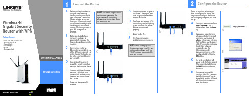
BUSINESS SERIESWireless-NPackage Contents•User Guide and QuickVPN ClientSoftware on CD-ROM•Network Cable•Power Adapter•Stands•R egistration Card1NOTE: Before setting up theRouter, make sure your PCs areconfigured to obtain an IP (orTCP/IP) address automaticallyfrom the Router.A Before you begin, make surethat you have the setupinformation for your specifictype of Internet connection.The installation technicianfrom your ISP should have leftthis information with you afterinstalling your broadbandconnection. If not, you can callyour ISP to request thesettings.B Make sure that all of yournetwork’s hardware ispowered off, including theRouter, PCs, and cable or DSLmodem.C Connect one end of anEthernet network cable to oneof the LAN ports (labeled 1-4)on the back of the Router, andthe other end to an Ethernetport on a PC.D Repeat step C to connectmore PCs, a switch, or othernetwork devices to the Router.E Connect a different Ethernetnetwork cable from yourcable or DSL modem to theInternet port on the Router’sback panel.F Power on the cable or DSLmodem.G Connect the power adapter tothe Router’s Power port, andthen plug the other end intoan electrical outlet.H The Power and Internet LEDson the front panel will light upgreen as soon as the poweradapter is connectedproperly.I Power on the PCs.J The Router’s hardwareinstallation is now complete.Connect the RouterGigabit SecurityRouter with VPNCEGWirelessNOTE: For details on placementoptions such as using thestands or wall-mounting,please refer to the User Guideon the CD-ROM.These instructions will show youhow to configure the Router. Youonly need to configure the Routeronce using any computer you haveset up.A Open your web browser. Enterhttp://192.168.1.1 in itsAddress field. Press the Enterkey.B A password request screenwill appear. Enter the defaultuser name and password,admin, in lowercase letters inthe User Name and Passwordfields. (For added security, youshould later set a newpassword, using theAdministration tab’sManagement screen of theweb-based utility). Click theOK button.C The web-based utility willappear with the Setup tab andIP Versions selected. Click onthe WAN option under theSetup tab.D If requested by your ISP(usually cable ISPs), completethe Host Name and DomainName fields, and the MTU andMTU Size fields. Otherwise,leave the defaults.2Configure the RouterACBG To configure the Router for your wireless network, select the Wireless Tab’s Basic Wireless Settings screen.HNetwork Name (SSID). The SSID is the network name shared by all devices in a wireless network. It iscase-sensitive and must not have more than 32 characters (use any keyboard character). For added security, change the default SSID (linksys) to a unique name.ISelect the Wireless Network Mode .Mixed: If your network has Wireless-N, -G, and -B devices, then keep the default, Mixed.Disable: To disable wireless networking, select Disable.JWireless Channel . Select the appropriate channel to be used between your Wireless Router and your clientdevices. The default is channel 6. You can also select Auto so that your Wireless Router will select the channel with the lowest amount of wireless interference while the system is booting up.Automatic - DHCPStatic IPPPPoEEFor the Connection Type setting, six connection types are offered through thedrop-down menu. Each Setup screen and available features will vary depending on which connection type you select.If using PPTP , Heartbeat Signal, or L2TP , refer to the User Guide on the CD.Internet Connection Type Automatic Configuration -DHCP : If you are connecting through DHCP or a dynamic IP address from your ISP , keep this default setting.Static IP : If your ISP assigns you a static IP address, select Static IP from the drop-down menu. Complete the Internet IP Address, Subnet Mask, Default Gateway, and DNS fields. You need to enter at least one DNS address.PPPoE : If you are connecting through PPPoE, select PPPoE from the drop-down menu. Complete the User Name and Password fields.FWhen you are finished entering your Internetconnection settings, click the Save Settings button to save your changes.KWireless SSID Broadcast . When wireless clients survey the local area for wireless networks to associate with, they will detect the SSID broadcast by the Router. To broadcast the Router's SSID, keep the default, Enabled. If you do not want to broadcast the Router's SSID, then select Disabled.LWhen you are finishedentering your Basic Wireless Settings, click the SaveSettings button to save your changes.M Power your broadbandmodem off and back on again.N Restart or power on your PCs so they can obtain the Router’s new settings.OTo test the Router’s settings, open your web browser from any computer. In thebrowser’s Address field, enter /registration and press the Enter key.NOTE: For more advancedsettings and security options, refer to the User Guide on the WRVS4400N CD.A Open the Router’s Web Utility as shown in Step 2, and select the Wireless Tab’s Wireless Security screen.BSelect a security method: For WEP , WPA Enterprise, WPA2-Enterprise, andWPA2-Enterprise Mixed, refer to the User Guide on the CD.For WPA-Personal , WPA2-Personal , and W PA2-Personal Mixed ,follow the instructions below:Select the option you want, WPA-Personal , WPA2-Personal , or WPA2-Personal Mixed . Configure the following:Encryption - If WPA-Personal is selected, select the method you want to use, TKIP or AES .Pre-shared Key - Enter a key of 8-63 characters.Key Renewal - In most cases, you can keep the default, 3600 seconds.CClick the Save Settings button.Congratulations! The installationof the Router is complete.Linksys is a registered trademark or trademark of Cisco Systems, Inc. and/or its affiliates in the U.S. and certain other countries. Copyright © 2006 Cisco Systems, Inc. All rights reserved.WRVS4400N-QI-60623NC RRFor additional information or troubleshooting help, refer to the User Guide on the Setup CD-ROM. You can also call or e-mail for further support.24-hour Technical Support 800-326-7114(toll-free from US or Canada)E-mail Support*******************Website or RMA (Return Merchandise Authorization)/support FTP Siteftp:// Sales Information800-546-5797 (800-LINKSYS)3Configure Wireless SecurityWPA-PersonalWPA2-PersonalG。
Checkpoint4400参数表

4400
企业级安全设备(223 SPU/5Gbps)— 快速联
网以及光纤和铜缆连接
选项
Check Point 4400 设备
目前,企业网关不仅是防火墙。它是为应对日益增多的复杂威胁而提供的一款安 全设备。作为企业安全网关,它必须使用多种技术来控制网络访问,检测复杂攻 击,并提供其它安全能力,如数据丢失防护和防御基于 Web 的威胁等。而智能手 机和平板电脑等移动设备的扩散以及新型流媒体、社交网络和 P2P 应用软件则需 要更大的连接容量和新的应用控制技术。最终,企业向私有云和公共云服务的转 型从各个方面改变了公司的边界,这需要更强的性能和额外的安全解决方案。
主要特点
223 SecurityPower 5 Gbps 防火墙吞吐量 3.5Gbps IPS 吞吐量 多达 12 个 10/100/1000Base-T 端口 多达 4 个 1GbE 光纤端口 1 个机架单元设备
主要优点
入门级企业安全设备
通过一台设备提供保证你的网络安全 所需的一切 通过一个集成管理控制台简化管理
1 2012 年第 1 季度可用 2 SecurityPower:一种根据真实世界流量模型和所选择部署的软件刀片来测量 设备性能衡量标准。为你的性能和安全需求找到正确的设备。
高可用性 主动/主动 - L3 模式 主动/被动 – 透明& L3 模式 防火墙和 VPN 会话同步 会话失效转移,路由变化
设备故障检测
每种 Check Point 设备都支持 Check Point 的 3D 安全远景规划,后者将策略、人和 执行结合在一起,提供无与伦比的安全防护,并针对下列软件刀片的任意组合进 行优化:(1)防火墙,(2)VPN,(3)IPS,(4)应用控制,(5)移动访问, (6)DLP,(7)URL 过滤,(8)反病毒,(9)反垃圾邮件,(10)身份识别, (11)高级联网和集群。
WRVS4400N_v2.0_Firmware_v2.0.2.1_Release_Notes
Release Notes Release Notes for WRVS4400N Version2.0 Firmware2.0.2.1June 2011These Release Notes describe updates and known issues in WRVS4400Nfirmware version 2.0.2.1.!CAUTION Firmware images that support the WRVS4400N v2.0 hardware are not backward-compatible with the WRVS4400N v1.0 and v1.1 hardware. Do not try to upgradeyour v1.0 or v1.1 hardware with firmware that is intended for use with the v2.0. Thesame applies to the v1.0 and v1.1 hardware firmware versions. Older firmwareversions cannot be loaded onto WRVS4400N v2.0 hardware.ContentsThis document includes the following topics:•Changes Since WRVS4400N Firmware Version 2.0.1.3•Changes Since WRVS4400N Firmware Version 2.0.0.8•Changes Since WRVS4400N Firmware Version 2.0.0.7•Changes Since WRVS4400N Firmware Version 1.00.09•Related InformationRelease NotesChanges Since WRVS4400N Firmware Version 2.0.1.3UpdatesThe following updates were made in firmware version 2.0.2.1:•Updated the text of the Note field on the Wireless > WDS window.•Added a logout link to the Home page.•Updated the Firewall > Internet Access Policy window so that when a useradds an allow-rule policy, the user can only add allow rules to the policy, butnot deny rules.•Updated the Internet access policy so that it supports overnight scheduling.Fixed ProblemsThe following problems were fixed in firmware version 2.0.2.1:•The DHCPv6 section of the Setup > LAN section does not reflect thecorrect DHCPv6 starting and ending IP pool addresses.•If the PPPoE username or password include special characters, the PPPoEconnection fails.•The Firewall > Internet Access Policy window displays the wrong messagewhen you change Deny to Allow.•Internet filtering does not work if GET and HOST are split.•Messages prompting the user for acknowledgement display a YES buttoninstead of an OK button.•No example of a forbidden domain construct in the GUI.•The Approved URLs list displays an incorrect example of the syntax of aURL.•Typo in the error message that is displayed when entering an IP addressesthat is already in the Approved Clients list.•No validation for the IP address ranges in the Approved Clients list.•There is an issue in the process of generating random certificates.Release Notes•In the L2 Switch > VLAN window, highlighting all VLANs (2–4) and deleting VLAN ranges is misleading because some of the selected items remain in the list.•Rebooting the router causes clients on non-default VLANs to lose their IP addresses and acquire IP addresses from the default VLAN (1).•The broadcast IP address should not be allowed as the Gateway address when adding route.•Incorrect error message displayed when adding a duplicate static route.•Daylight savings time is incorrect for Time Zone GMT -6 (Central Time US and Canada).•User cannot use the WAN IP address to locally access the GUI using HTTPS.•SMTP update is needed so that the user can enter the port number.•HTML tags are displayed when the Disconnect button is clicked on the Summary window.•Fixed several web interface vulnerabilities that could be exploited by a remote, unauthenticated user. For more information, see the following Cisco Security Advisory:/en/US/products/products_security_advisory09186a0080b7f190.shtmlRelease NotesChanges Since WRVS4400N Firmware Version 2.0.0.8Fixed ProblemsThe following problems were fixed in firmware version 2.0.1.3:•Fixed an issue that caused the RIP packet size to grow larger over time.•Fixed an issue that caused a duplicate “default route” entry to show up inthe routing table.•Fixed a session logout issue by enabling a Log Out button.•Fixed an issue that caused the router to become unresponsive andunrecoverable after the reset button during a firmware upgrade.•Fixed an issue in the SIP-ALG code that caused a blind call transfer fromone IP Phone to another IP Phone to fail.•Fixed both of the QuickVPN user name and password fields to support acharacter length of up to 32 characters maximum.•Fixed an issue that caused some printers to be unable to print over an IPSecVPN tunnel between two physical locations.•Fixed an issue that caused the TrendMicro ProtectLink Gateway feature tofail to filter URLs if a customer accessed the URL through search resultswhen the approved URL list had any URL entered.•Fixed an issue that caused IPv6 packets between different VLAN’s to not beblocked if inter-VLAN routing is disabled.•Fixed an issue that caused a QuickVPN tunnel to not be re-establishedwhen more than “any” remote gateway is configured for the tunnel settings.•Fixed an issue that caused port forwarding rules to stop if IPS was disabled.•Fixed an issue that caused the DDNS status to always show “Please Wait” inthe web-based management interface of the router.•Fixed an issue that caused WDS to not allow more than one access point toconnect to the WRVS4400N for wireless repeater support.•Converted the style of the ProtectLink Gateway administration page to thestyle of the current ProtectLink Web administration page.•Fixed an issue found in the Time Zone setting that caused the system timeto be incorrect when the Time Zone is set to “(GMT-03:30) Newfoundland.”Release Notes•Fixed an issue in the SIP-ALG code that caused certain SIP packets to betagged with the incorrect VLAN ID.•Fixed an issue with WDS that caused the router wireless driver to beunresponsive when trying to get a WAP4410N access point to associate toWRVS4400N.•Fixed an issue in the VPN code that caused the QuickVPN client to drop theconnection when the QuickVPN client connects to the QuickVPN serverbehind a NAT router.Known IssuesThe following is a list of known issues:•After the you log into the router’s web-based configuration utility, you couldopen a new browser window or tab and access the configuration utilitywithout having to re-authenticate.•If your computer is on the same LAN as the WRVS4400N router, you cannotlog into the router’s web-based configuration utility using the router’s WANIP address. You must use the LAN IP address instead.•The RIP network mask shows incorrectly when the VLAN LAN IP is set as10.0.2.1.•eMule(0.48a) can’t be blocked by IPS.Changes Since WRVS4400N Firmware Version 2.0.0.7Updated the wireless driver to improve WLAN adapter interoperability betweendifferent WLAN adapter vendors.Release NotesChanges Since WRVS4400N Firmware Version 1.00.09Problems were fixed.Fixed ProblemsThe following problems were fixed in firmware version 2.0.2.1:•Fixed an issue that caused voice packets to become incorrectly routedduring call transfers between 3 or more IP phones.•Fixed an issue that caused the QuickVPN client to not allow the completetransfer of more than 100 MB of a large file over a VPN tunnel.•Fixed an issue in the SIP ALG where the session originator sends a packetwith source port 1028, but the via port in the SIP message is 5060.•Fixed an issue caused when the router does not map a 4-digit number tothe correct IP address of a phone registered to at the SIP server.•Corrected the pop-up message on the DMZ page to be “DMZ IP Addresscontains an invalid number.”•Corrected the pop-up message on the DMZ page to be “DMZ IP Address isinvalid. Valid range is 1 to 254.”•Fixed an issue that caused the checking mechanism used on the ApprovedClients IP page to function incorrectly.•Corrected the text “Sec.” to be “sec” for the Key Lifetime filed on the IPSecVPN T unnel setup page.•Corrected the text for IP Conntrack window title to be “IP Conntrack” andnot “IP Conntracks”.•Corrected a spacing issue on the QoS Bandwidth Management page of theweb-based GUI.•Fixed an issue caused when using Firefox 3.5 to view the web-based GUIthat caused the text on the navigation toolbar to become blurry.•Fixed an issue with WLAN client performance in mixed mode environmentsthat allows for increased interoperability with more WLAN clients.•Corrected the text on the Firewall Port Range Forwarding page.Release Notes•Fixed an issue caused when the LAN IP address of the local router is used in the IPSec VPN Tunnel configuration for the remote group setting.•Fixed an issue caused when the Timezone setting is changed, which caused ProtectLink URL filtering to become unstable.•Fixed the Trend Micro Protectlink URL used during account registration. This URL is used by Trend Micro to identify which product is being used.•Fixed an issue in the Firewall page that caused the page to be displayed incorrectly when clicking the Save button twice when accessing the router remotely via HTTPS.•Fixed an issue that did not allow a fully-qualified domain name to be used in the Syslog server field.•Changed the “O” field value of certificates from “Cisco” to “Cisco System, Inc.”•Fixed an issue that slowed Internet access after a user enabled the Trend Micro ProtectLink feature.•Fixed and issue that caused outbound logging to become unstable.•Fixed an issue that caused the router WAN setup page to display incorrectly when using Internet Explorer 7.•Fixed an issue on the VPN setup page that caused the page to become unresponsive when adding a new IPSec policy.•Fixed an issue that allowed the router to save invalid LAN IP.•Fixed an issue on the Administration Management page that allowed duplicate usernames to be saved.•Fixed an issue that caused the router VLAN IP to not save correctly.•Fixed an issue on the IP Based ACL page that caused the check boxes to not become greyed out after clicking the “Disable All Rules” button.•Fixed an issue on the VPN Summary page that shows the number of available IPSec VPN tunnels incorrectly.•Fixed an issue that caused the router web-based GUI to not allow the removal of router usernames.•Corrected a typo in the pop-up message that appeared when adding the same username to the Router Access page.Release Notes•Fixed an issue in the Traceroute feature to check for valid input beforeexecuting.•Fixed an issue that allowed a user to configure and save an invalid characterstring in the Syslog Server field.•Rebranded the web-based GUI from the Linksys to the Cisco design.•Fixed an issue in the IPv6 DHCP server that caused the DHCP server tobecome unresponsive.•Fixed the QVPN client so that it does not reconnect to the router afterdisconnecting.•Fixed the QVPN connection to WRVS4400Nv1.1 so that the connection doesnot stay active.•Improved DMZ WAN-to-LAN performance.•Fixed Forbidden Domain failure. If *any* IP based ACL rules are present thenthe any Forbidden Domains or Keywords present in the Internet AccessPolicy are not be applied.•Fixed an issue with DNS source port changing incorrectly.•Fixed an issue that caused the PPTP passthrough to fail to connect to aPPTP server.•Replaced the wireless default SSID with ciscosb.•Fixed an issue that caused WDS not to be supported when the securitymode is WPA/WPA2.•Corrected the SNMP OID to 1.3.6.1.4.1.9.6.1.22.250.2.•Updated the IPS code to not check for the old Linksys MAC address usedbefore rebranding.Known Issues•RIP network mask shows incorrectly when setting a VLAN LAN IP as10.0.2.1.•eMule(0.48a) can’t be blocked by IPS.Release Notes Related InformationCisco, Cisco Systems, the Cisco logo, and the Cisco Systems logo are registered trademarks or trademarks of Cisco Systems, Inc. and/or its affiliates in the United States and certain other countries. All other trademarks mentioned in this document or Website are the property of their respective owners. The use of the word partner does not imply a partnership relationship between Cisco and any other company. (0705R)© 2010 Cisco Systems, Inc. All rights reserved.OL-20703-01 SupportCisco Small Business SupportCommunity /go/smallbizsupportOnline T echnical Support and Documentation (Login Required)/supportPhone Support Contacts/en/US/support/tsd_cisco_small_business _support_center_contacts.html Software Downloads(Login Required)Go to /support/downloads , and enter the model number in the Software Search box.Product DocumentationCisco Wireless-N GigabitSecurity Router with VPNWRVS4400N /en/US/products/ps9923/tsd_products_support_series_home.htmlCisco Small BusinessCisco Partner Central for SmallBusiness (Partner LoginRequired)/web/partners/sell/smb Cisco Small Business Home/smb Marketplace /go/marketplace。
Nano Spider - ORG4400 评估套件数据表单说明书

NANO SPIDER (ORG4400) EVALUATION KITDatasheetO r i g i n G P S . c o mINDEX1. SCOPE (4)2. DISCLAIMER (4)3. SAFETY INFORMATION (4)4. ESD SENSITIVITY (4)5. CONTACT INFORMATION (4)6. RELATED DOCUMENTATION (4)7. REVISION HISTORY (5)8. ABOUT SPIDER FAMILY (5)9. ABOUT MULTI SPIDER MODULE (5)10. ABOUT ORIGINGPS (6)11. DESCRIPTION (6)12. SCHEMATICS (7)12.1. MAIN BOARD SCHEMATICS (7)12.2. INTERFACE ADAPTOR SCHEMATICS (8)13. BILL OF MATERIALS (9)13.1. MAIN BOARD BILL OF MATERIALS (9)13.2. INTERFACE ADAPTOR BILL OF MATERIALS (9)14. ASSEMBLY AND LAYOUT (10)14.1. MAIN BOARD PCB (10)14.2. INTERFACE ADAPTOR PCB (12)15. TTL-232R-3V3 USB-Serial CONVERTER CABLE (15)16. ORG9802 MINIATURE PASSIVE ANTENNA ASSEMBLY (16)16.1. GENERAL (16)16.2. MECHANICAL SPECIFICATIONS (16)16.3. ELECTRICAL SPECIFICATIONS (17)17. ORG9805 EXTERNAL ACTIVE ANTENNA (18)17.1. DESCRIPTION (18)17.2. FEATURES (18)17.3. BENEFITS (18)17.4. BLOCK DIAGRAM (18)17.5. ELECTRICAL SPECIFICATIONS (19)17.6. MECHANICAL SPECIFICATIONS (20)18. I-PEX MHFIII TO SMA-TYPE COAXIAL CABLE ADAPTOR (21)TABLE INDEXTABLE 1 – RELATED DOCUMENTATION (4)TABLE 2 – REVISION HISTORY (5)TABLE 3 – MAIN BOARD BILL OF MATERIALS (9)TABLE 4 – INTERFACE ADAPTOR BILL OF MATERIALS (9)TABLE 5 –USB-SERIAL CONVERTER CABLE HEADER PIN-OUT (15)TABLE 6 –USB-SERIAL CONVERTER CABLE OPERATING PARAMETERS (15)TABLE 7 –ORG9802 MECHANICAL SPECIFICATIONS (16)TABLE 8 –ORG9802 ELECTRICAL SPECIFICATIONS (17)TABLE 9 – ORG9805 ELECTRICAL SPECIFICATIONS (19)TABLE 10 – ORG9805 MECHANICAL SPECIFICATIONS (20)FIGURE INDEXFIGURE 1 – MAIN BOARD SCHEMATICS (7)FIGURE 2 – INTERFACE ADAPTOR SCHEMATICS (8)FIGURE 3 – MAIN BOARD COMPONENTS PLACEMENT (10)FIGURE 4 – MAIN BOARD SOLDER MASK (10)FIGURE 5 – MAIN BOARD TOP LAYER ROUTING (11)FIGURE 6 – MAIN BOARD BOTTOM LAYER ROUTING (11)FIGURE 7 –INTERFACE ADAPTOR BOARD COMPONENTS PLACEMENT (12)FIGURE 8 – INTERFACE ADAPTOR BOARD SOLDER MASK (12)FIGURE 9 – INTERFACE ADAPTOR BOARD TOP LAYER ROUTING (13)FIGURE 10 – INTERFACE ADAPTOR INNER LAYER 1 ROUTING (13)FIGURE 11 –INTERFACE ADAPTOR INNER LAYER 2 ROUTING (14)FIGURE 12 – INTERFACE ADAPTOR BOTTOM LAYER ROUTING (14)FIGURE 13 – PIN HEADER SOCKET BOTTOM VIEW (15)FIGURE 14 – ORG9802 MECHANICAL OUTLINE (16)FIGURE 15 –ORG9802 S11 LOG MAGNITUDE (17)FIGURE 16 –ORG9802 S11 SMITH CHART (17)FIGURE 17 – ORG9805 BLOCK DIAGRAM (18)FIGURE 18 – ORG9805 MECHANICAL OUTLINE (20)FIGURE 19 – I-PEX MHFIII TO SMA-TYPE ADAPTOR MECHANICAL OUTLINE (21)1. SCOPEThis document describes the features and specifications of Nano Spider ORG4400 evaluation kit.2. DISCLAIMERAll trademarks are properties of their respective owners.Performance characteristics listed in this document do not constitute a warranty or guarantee of product performance. OriginGPS assumes no liability or responsibility for any claims or damages arising out of the use of this document, or from the use of integrated circuits based on this document.OriginGPS assumes no liability or responsibility for unintentional inaccuracies or omissions in this document. OriginGPS reserves the right to make changes in its products, specifications and other information at any time without notice.OriginGPS reserves the right to conduct, from time to time, and at its sole discretion, firmware upgrades.As long as those FW improvements have no material change on end customers, PCN may not be issued. OriginGPS navigation products are not recommended to use in life saving or life sustaining applications.3. SAFETY INFORMATIONImproper handling and use can cause permanent damage to the product.4. ESD SENSITIVITYThis product is ESD sensitive device and must be handled with care.5. CONTACT INFORMATIONSupport -or Online Form Marketing and sales -***********************Web –6. RELATED DOCUMENTATIONTABLE 1 – RELATED DOCUMENTATION7. REVISION HISTORYTABLE 2 – REVISION HISTORY8. ABOUT SPIDER FAMILYOriginGPS GNSS receiver modules have been designed to address markets where size, weight, stand-alone operation, highest level of integration, power consumption and design flexibility - all are very important.OriginGP S’ S pider family breaks size barrier, offering the industry’s smallest fully-integrated, highly-sensitiveGPS / GNSS modules.Spider family features OriginGPS' proprietary NF Z™ technology for high sensitivity and noise immunity evenunder marginal signal condition, commonly found in urban canyons, under dense foliage or when the receiv er’s position in space rapidly changes.Spider family enables the shortest TTM (Time-To-Market) with minimal design risks.Just connect an antenna and power supply on a 2-layer PCB.9. ABOUT NANO SPIDER MODULENano Spider is a complete SiP featuring LGA SMT footprint designed to commit unique integration features for high volume cost sensitive applications.Designed to support ultra-compact applications such as smart watches, wearable devices, trackers and digital cameras, Nano Spider ORG4400 module is a miniature multi-channel GPS with SBAS, QZSS and other regional overlay systems receiver that continuously tracks all satellites in view, providing real-time positioning data in industry’s standard NMEA format.Nano Spider ORG4400 module offers superior sensitivity and outstanding performance, achieving rapidTTFF in less than one second, accuracy of approximately two meters, and tracking sensitivity of -163dBm. Sizedonly 4.1mm x 4.1mm Nano Spider ORG4400 module is industry’s small sized, record breaking solution. ORG4400 module integrates LNA, SAW filter, TCXO, RTC crystal shield with market-leading SiRFsta rIV™ GPS SoC.Nano Spider ORG4400 module is introducing industry’s lowest energy per fix ratio, unparalleled accuracy and extremely fast fixes even under challenging signal conditions, such as in built-up urban areas, dense foliage or even indoor. Integrated GPS SoC incorporating high-performance microprocessor and sophisticated firmware keeps positioning payload off the host, allowing integration in embedded solutions with low computing resources.Innovative architecture can detect changes in context, temperature, and satellite signals to achieve a state of near continuous availability by maintaining and opportunistically updating its internal fine time, frequency, and satellite ephemeris data while consuming mere microwatts of battery power.10. ABOUT ORIGINGPSOriginGPS is a world leading designer, manufacturer and supplier of miniature positioning modules, antenna modules and antenna solutions.OriginGPS modules introduce unparalleled sensitivity and noise immunity by incorporating Noise Free Zone system (NFZ™) proprietary technology for faster position fix and navigation stability even under challenging satellite signal conditions.Founded in 2006, OriginGPS is specializing in development of unique technologies that miniaturize RF modules, thereby addressing the market need for smaller wireless solutions.11. DESCRIPTIONEvaluation Kit of the ORG4400 GPS Module comprises the Demo Board, USB to UART Serial Converter Cable, ORG9802 Miniature Passive Antenna Assembly, I-PEX MHFIII to SMA-type Coaxial Cable Adaptor, ORG9805External Active Antenna, support CD with GPS simulator software for PC and documentation.The Demo Board assembly is built of Main Board, incorporating 3.3V LDO voltage regulator, UARTconnector, push-button tactile switch for Push-To-Fix™interrupt and various test points.The ORG4400 GPS Module is soldered onto the Main Board through the Interface Adaptor.The Interface Adaptor includes a single-bit buffer for voltage level translation of TX line, 1.8V LDO voltage regulator, Load Switch for active antenna T-bias and a voltage supervisor for autonomous power-on pulse generation.ARev Authored By:Sheet of A0011 I. Divinsky1Rev SheetAuthored By:ofA0011I. Divinsky GND 8RESET ON_OFF RTS WAKEUP GND 913. BILL OF MATERIALS13.1 MAIN BOARD BILL OF MATERIALSTABLE 3 - MAIN BOARD BILL OF MATERIALS13.2 INTERFACE ADAPTOR BILL OF MATERIALSTABLE 4 - INTERFACE ADAPTOR BILL OF MATERIALS14. ASSEMBLY AND LAYOUT14.1 MAIN BOARD PCBMain Board for the ORG4400 GPS Module is 2-layer 1.6mm thickness FR4 PCB.FIGURE 3 - MAIN BOARD COMPONENTS PLACEMENTFIGURE 4 - MAIN BOARD SOLDER MASKFIGURE 5 – MAIN BOARD TOP LAYER ROUTINGFIGURE 6 – MAIN BOARD BOTTOM LAYER ROUTING14.2 INTERFACE ADAPTOR PCBInterface Adaptor Board for the ORG4400 GPS Module is 17mm x 17mm 22 pads 4 layers 0.6mm thickness FR4 PCB.FIGURE 7 - INTERFACE ADAPTOR BOARD COMPONENTS PLACEMENTFIGURE 8 - INTERFACE ADAPTOR BOARD SOLDER MASKFIGURE 9 - INTERFACE ADAPTOR BOARD TOP LAYER ROUTINGFIGURE 10 - INTERFACE ADAPTOR INNER LAYER 1 ROUTINGFIGURE 11 - INTERFACE ADAPTOR INNER LAYER 2 ROUTINGFIGURE 12 - INTERFACE ADAPTOR BOTTOM LAYER ROUTING15. TTL-232R-3V3 USB-Serial CONVERTER CABLE*The TTL-232R-3V3 is a USB to Serial converter cable that provides a simple way to connect devices with UART interface to PC.The TTL-232R-3V3 uses an FTDI FT232RQ IC which is housed inside the USB Type 'A' connector and is terminated at the end of a 1.8 meter cable (6 ft.) with a 2.54mm (“0.1) pitch header socket which provides an access to UART standard Transmit Data (TxD) and Receive Data (RxD). These lines are operating at 3.3V LVTTL levels. Also brought out on the header are +5V and GND.FIGURE 13 - PIN HEADER SOCKET BOTTOM VIEWTABLE 5 - USB-SERIAL CONVERTER CABLE HEADER PIN-OUTTABLE 6 - USB-SERIAL CONVERTER CABLE OPERATING PARAMETERS*Note: For more information refer to FTDI Ltd. TTL-232R TTL To USB Serial Converter Range Of Cables Datasheet, Document Reference No.: FT_00005416. ORG9802 MINIATURE PASSIVE ANTENNA ASSEMBLY*16.1 GENERALORG9802 is a miniature antenna assembly, comprising four components: 1. Ceramic patch antenna element 2. Adaptor PCB 3. Coaxial cable 4. Connector16.2 MECHANICAL SPECIFICATIONSFIGURE 14 - ORG9802 MECHANICAL OUTLINETABLE 7 - ORG9802 MECHANICAL SPECIFICATIONS*Note: For more information refer to OriginGPS ORG9802 Patch Antenna Assembly Datasheet, Document number 30031116.3 ELECTRICAL SPECIFICATIONSTABLE 8 - ORG9802 ELECTRICAL SPECIFICATIONSTYPICAL S11FIGURE 15 - ORG9802 S11 LOG MAGNITUDE FIGURE 16 - ORG9802 S11 SMITH CHART17. ORG9805 External Active Antenna*17.1 DESCRIPTIONThe ORG9805 External Active Antenna incorporates high-efficiency ceramic patch antenna element, high out- of-band rejection band-pass Surface Acoustic Wave (SAW) filter, low Noise Figure and high gain Low Noise Amplifier (LNA), enclosed in plastic case, with coaxial cable terminated by standard SMA-type plug. The ORG9805 Active Antenna with highest GPS-band performance and notch filtering for out-ofband signals provides exceptional sensitivity, high selectivity and noise immunity. The ORG9805 Active Antenna is built of highest quality materials and components.The ORG9805 Active Antenna is the perfect match to the OriginGPS GPS receiver modules.17.2 FEATURES∙ Antenna element with high efficiency for excellent coverage of GPS satellites ∙ SAW filter for rejection of out-of-band signals∙ LNA with low Noise Figure and high gain for high sensitivity ∙ Plastic case with magnetic base∙ RG-174 flexible coaxial cable of 5m length ∙ SMA-type gold plated plug17.3 BENEFITS▪ High performance ▪ Compact size ▪ Easy integration17.4 BLOCK DIAGRAMFIGURE 17 - ORG9805 BLOCK DIAGRAMRF out DC in*Note: For more information refer to OriginGPS ORG9805 External Active Antenna Datasheet, Document number 160112TABLE 9 - ORG9805 ELECTRICAL SPECIFICATIONSTABLE 10 - ORG9805 MECHANICAL SPECIFICATIONSFIGURE 18 - ORG9805 MECHANICAL OUTLINEPage 21 of 21March 10, 2015 Nano Spider - ORG4400 Evaluation Kit Datasheet Revision 1.018. I-PEX MHFIII TO SMA-TYPE COAXIAL CABLE ADAPTORFIGURE 19 - I-PEX MHFIII TO SMA-TYPE ADAPTOR MECHANICAL OUTLINE。
4400系列电源包安装和操作说明书

PERLICK CORPORATION 8300 W. Good Hope Road, Milwaukee, WI 53223 • 800.558.5592 • MODELS 4400 Series 44044414-23044104410W 44144414W 44204420WCUSINSTALLATION AND OPERATION INSTRUCTIONS4400 SERIES POWER PAKSIMPORTANT INFORMATIONTo register your product, visit our web site at . Click on Commercial , then Service . You will see the link to Warranty Registration Form . You must complete and submit this form or the installation date will revert back to the ship date.Permanently mount the enclosed Warning/Safety Instruction label in a visible location near the CO2 regulator.This manual has been prepared to assist you in the installation of your Century Remote Beer System and to acquaint you with its operation and maintenance. We dedicate considerable time to ensure that our products provide the highest level of customer satisfaction. If service is required, your dealer can provide you with a list of qualified service agents. For your own protection, never return merchandise for credit without our approval.We thank you for selecting a Perlick product and assure you of our continuing interest in your satisfaction.Table of ContentsSizes & Specifications ............................................2-3 Air-Cooled Models .................................................2 Water-Cooled Models ............................................3 General Information ..........................................4 Installation ........................................................5 Connecting Power Pak to Trunk Housing ..............6 Connecting to Trunk Housing ................................7Power Pak Start-Up ...................................................8LEDS .........................................................................9Preventative Maintenance .........................................9Replacement Parts ..................................................10Wiring Diagrams (11)Form No. Z2020Rev. 11.30.2022(Ground, Neutral, Hot-Power, Hot-Power)AC: 115 - 208/240v, 60 HZ, Split Single PhaseC US(Ground, Neutral, Hot-Power, Hot-Power)AC: 115 - 208/240v, 60 HZ, Split Single PhaseCUSPRODUCT DESCRIPTIONPower Paks have always been an integral part of a Perlick Century Beer System. The 4400 Series Power Pak product line has been expanded to satify longer beer runs. A Power Pak circulates coolant solution (food grade propylene glycol with distilled water) fromwalk-in cooler to the dispensing station(s) and back,maintaining the desired dispensing temperature at the faucet. The 4400 series Power Pak incorporate a 1/3 hp ball bearing, maintenance free motor with a 100 gallon per hour 150 psig positive displacement pump for optimum performance. The 4400 series Power Pak product line employs a direct expansion form of refrigeration increasing the units’ efficency aswell as making the units more compact. These unitsalso employ an electronic temperature control with digital readout. This state of the art control controlsthe performance of the unit as well as giving theuser a visual indication of the how the unit is workingas well as giving the user a visual indication of the how the unit is working as well as early indication if something may be going wrong through the use of internal alarms.AccessoriesPower Cord KitC2296A-20--12/3 Cord, 20A, Nema Plug 5-20P, Dedicated Circuit Models - See above electrical specificationsPower Pak Racks61790, 61790+1, 61790+2 - All ModelsPower Pak Wall Mounting BracketsFor Models 4404 & 4410 onlyCoolant Solution-63299-1One gallon Perlick Coolant solution, 30% DowFrost HD/70% Distilled Water Coolant Connector Kit 63335 - All Models Leg Set - All Models57782 . . . Set of four, 5 3/4”-71/2” adjustable legsPump Kits4430 - Pump kit, 115V, 6.1 A, 100 gph, 130 psigModels 4410, 4410W4431 - Pump kit, 115V, 5.6 A, 100 gph, 130 psig Models 4414, 4414W4432 - Pump kit, 230V, 2.8 A, 100 gph, 130 psig Models 4414-230, 4420WARNING: California Prop 65 NoticeThese products may expose you to chemicals i ncluding Chromium, which are known to t he state of California to cause cancer and b irth defects or other reproductive harm. For more information on whether a product in this list contains these chemicals, please refer to the specific product page at . Or to find out more about Prop 65, go to .4400 SERIES POWER PAKS - INSTALLATIONOperation/Installation ManualINSTALLATIONIMPORTANT SAFETY WARNINGS!• Follow all National and Regional Codes.• Read Installation and Operating Instructions carefully before attempting to install, operate or maintain the product.• Protect yourself and others by observing all safety information.• Electrical hazards exist and can cause injuries if not serviced by properly trained personnel.• Failure to comply with instructions could result in personal injury and/or property damage!• Retain instructions for future reference.• Never operate the circulating pump without coolant in the reservoir.NOTE: Air-cooled Power Paks must be installedin areas with adequate ventilation to maintain ambient temperatures of less than 105°F to achieve optimum performance and satisfy warranty requirements.INSTALLING THE POWER PAKPrior to installing a 4400 Series Power Pak, it isimperative that the method of connecting it to theelectrical service has been determined. Ensure thatthe electrical service to power the Power Pak willhandle the load requirements. Perlick has a PowerCord specifically designed for a Power Pak, which has a RLA of 16 amps or less, and a MCA of 20 amps orless. All units with RLA greater than 16 amps and aMCA of greater than 20 amps should have the Power Pak hard-wired to electrical service.ALL MODELS• Determine the ideal placement of the Power Pak.Locate the connection point to the truck housingand place the Power Pak as close to this point aspossible. NOTE: If the Power Pak is to be located on top of the walk-in cooler, it is imperativethat proper ventilation is provided to preventsystem failure due to overheating. Inadequateventilation will void warranty.• Place the Power Pak and Ensure that it is level to provide proper overflow protection. REMINDER: Allow a minimun of six inches of clearace on the louvered ends of the cabinet for proper airflow. Allow accessibility room on the top of the cabinet for serviceability.• Remove the top panels (2).• Ensure Power Switches for Condensing Unit and Pump(s) are in the OFF position. Make the electrical connections per ther illustrations. NOTE: Electrical circuit shold be a dedicated circuit for use only with the Power Pak. The circuit should be sized in accordance with the electrical requirements of each unit as well as in compliance with all National and Local Codes.• Plumb overflow port to a suitable reservior/drain.WATER-COOLED MODELS• In addition to the above installation instruction:• Care should be exercised in locating the PowerPak so that the unit will never be exposed to temperatures below freezing.• If the Power Pak is installing more than 5 feet higher than the remote outlet drain point (i.e., location of the floor drain) of the condenser, a vacuum breaker or open vent line should be provided to prevent the discharge line from creating a partial vacuum condition in the condenser water system.• If a water-circulating pump is used it should beplaced on the water supply side of the condenser, so water is being pushed through the condenser.• A potable water supply is required aswell as a drain or reclamation system. Make water supply connection to fitting labeled as the water inlet. Make outlet connection to fitting labeled as the water outlet connection. Both the inlet and outlet fittings supplied with the Power Pak are 1/2” Quick Connect fittings.• This equipment when equipped with a water-cooledcondenser, connected to a portable water supply system is to be installed with adequate backflow protection to comply with applicable federal, state and local codes.(Backflow protection not included.)CONNECTING POWER PAK TO TRUNK HOUSING 400 Series Power Paks require rigid fittings with a minimum pressure rating of 150 psig. Use Coolant Connector Kit #63335 to connect Power Pak to Trunk Housing.• Inspect pump outlet port for debris. Insert barbed fitting #63307 into pummp outlet port.• Inspect Glycol Return Manifold inlet for debris.Insert barbed fitting #63307 into return manifold inlet port.• Cut supplied coolant tubing, #54588, to required length to reach from Power Pak to Trunk Housing connection point.• Cut tubular insulation sleeve, #C12700, in half and install over previously cut coolant tubing.• Take Oetiker clamps, #54871-210, and install over coolant tubing ends.• Push coolant lines, one each over pump outlet barbed fitting #63307 and return manifold barbed fitting #63307.• Position Oetikers over barbed fitting and clamp securely.• Slide tubular insulation sleeves tightly against connection points. Use insulation tape as necessary to ensure an air tight seal to prevent excessive heat gain or condensation problems.• Drill a 3-1/2” diameter hole in walk-in cooler to accommodate coolant lines.• Install insulation donuts over hole (both inside and outside of cooler walls.• Slide large insulation sleeve, #57478, over remaining coolant tubing exposed to warm air conditions including inside walk-in cooler from Power Pak to Trunk Housing connection point. Seal and tape all seams to prevent excessive heat gain or condensation problems.• Slide coolant lines through 3-1/2” donut hole previosly cut in walk-in cooler wall.• Position Trunk Housing coolant lines and Coolant Connector kit lines in horizontal position, to alleviate condensation runoff into Trunk Housing.• Cut Trunk Housing coolant lines with tubing cutter to ensure clean burr free ends.• Take Oetikers clamps #54871-210, and install over coolant connector kit tubing ends.• Slide coolant connector kit tubing over the trunk housing coolant lines and secure using the Oetikers.• Complete the insulation process by ensuring that all coolant lines are well insulated including all seams to prevent excessive condensation and heat gain.• Seal donut hole to ensure an air tight seal to prevent walk-in cooler problems as well as condensation. CONNECTING TRUNK HOUSING COOLANT LINES TO DISPENSING HEAD• Position the trunk housing so that beverage lines can be connected with a minimum cutting.• Split trunk housing approximately 12 inches from the end to allow working room for the connections.• Cut and deburr copper coolant lines coming from trunk housing and dispensing head. Stagger the lengths.• Connect trunk housing coolant lines to dispensing head coolant lines using clamps, hose and 3/8”x 1/2” union, included in Head connecting kit, #63486. Ensure that coolant lines are fully clample to guarantee a leak free connection.SYSTEM START-UPUse only Perlick Approved Coolant Solution, #63299-1, all other solutions and mixtures will void the Perlick warranty. The Coolant Solution has been pre-mixed for optimum performance and wear protection. The Power Pak resevoir holds approximately 1.75 gallons of solu-tion. It takes approximately 1 gallon of Coolant Solution to fill every 60 feet of Perlick Trunk Housing.• Never operate the circulating pumps without coolant in the resevoir.• Fill Power Pak resevoir with Perlick Coolant Solution.• Turn condensing unit switch and pump switch to the ON position. Coolant solution level will begin to drop in resevoir.• Continue adding Perlick Coolant Solution until no air bubbles are apparent from the Coolant return line. NOTE: Never allow for the Coolant level in the resevoir to drop below the heat exchanger tube inlet. Allowing the level to drop below the inlet will allow air into the lines.• Fill Power Pak reservoir until both the return line fitting port and the overflow tube port are submersed under Coolant Solution. Watch return line fitting port for additional Coolant Solution may need to be added.• Thoroughly check all field connection points for leaks.• Monitor Power Pak Temperature read-out to ensure Power Pak is working properly. Dependent on length of trunk housing run(s) and surrounding ambient conditions, these factors will determine how long it takes for the Power Pak to cut-out on the temperature control. DIGITAL TEMPERATURE CONTROLLERThe 4400 Series Power Pak comes equipped with a Factory Programmed Electronic Thermostat with display. The Thermostat has numerous factory settings, which should never be adjusted or tampered with to ensure proper operation of the Power Pak. The Thermostat has been factory programmed to cut-out at 30°F with a hysteresis/differential of 4°F.Front Panel Commands–Normal OperationSET:To display target set point.DEFROST:To start a manual defrost. (This feature is avail-able, however, the parameters for actuation are pro-grammed, such that, no defrost is available).Front Panel Commands–Programming Mode SET:Selects a parameter or confirms an operation.UP ARROW:Browses the parameter codes or increases the dis-played value.DOWN ARROW:Browses the parameter codes or decreases the dis-played value.Meaning of LEDSLED MODE FUNCTION SNOWFLAKE ON CompressorEnabled SNOWFLAKE FLASHING Programing Phase (flashingwith DEFROST) Anti-short cycledelay enabled DEFROST FLASHING Programming Phase (flashingwith SNOWFLAKE) Drip time inprogress DISPLAY MESSAGE MEANINGSMESSAGE MEANINGPOF Keyboard is locked out. Noparameters can be adjustedwithout unlocking the keyboard. ALARM MEANING ACTIONEE Data or Consult Factorymemory failureP1 Room probe Numerous - seefailure note 1NOTE 1: Faulty probe, loose connection, broket wire. (Power Pak will continue to operate with a faulty probe. The controller has been factory programmed to continue operation with the compressor cycling on and off in 5 minute intervals.How to see the SETPOINT• Press and immediately release the SET key: the display will show the Set point value.• Press and immediately release the SET key or wait for 5 seconds to display the probe value again. How to change the SETPOINT• Press and hold the SET key for more than 2 seconds to change the Set point value.• The value of the set point will be displayed and the SNOWFLAKE LED starts blinking.• To change the Set value, press the UP or DOWN ARROWS, dependent on the new set point value.• To memorize the new set point value, press the SET key again or wait 15 seconds.WARNING:IF MESSAGE OR INFORMATION SHOWN ON READOUT IS UNFAMILIAR, ALLOW CONTROL TO SIT FOR A MINIMUN OF 15 SECONDS AND CONTROLLER SHOULD RETURN TO DISPLAY PROBE TEMPERATURE.Perlick is committed to continuous improvement. Therefore, we reserve the right to change specifications without prior notice11Form No. Z2020Rev. 11.30.2022Wiring Diagram For 414-230, 4420, AC115 - 208/240, 60 HZ Power Paks (4 Wire AC Power Source Required)Wiring Diagram For 4404, 4410, 4414 115V Power PaksForm No. Z2020Rev. 11.30.2022 PERLICK CORPORATION 8300 W. Good Hope Road, Milwaukee, WI 53223 • 800.558.5592 • 。
阿尔卡特4400交换机操作
2007年12月ALCATELA4400用户操作及培训资料ALCATELA4400用户操作及培训资料目录目录1. 4400交换机机架简介2. 4400交换机功能板简介3. 4400交换机系统命令4. 开关机方法及注意事项5. 4400交换机系统数据管理6. mgr 管理工具7. 分机管理8. 组管理9. 中继管理10. 号码编译11. 类别管理12. 用户数据备份4400交换机机架简介左图为4400机架ACT 是用于插交换机功能板的分架.ACT编号从0开始(如:ACT0,ACT1).4400有两种ACT,ACT14和ACT28.ACT14有14个槽口,可插14块功能板(如左图的ACT1);ACT28有28个槽口,可插28块功能板(左图中的ACT2).系统有固定的设备号(即物理地址),设备号由ACT号,槽口号和功能板上的电路号组成(如:ACT0上的第5槽口的UA32板上的第一个端口的设备号为0-5-0,ACT1上的第11槽口的UA32板上的最后一个设备号为1-11-31)4400交换机功能板简介CUP-3,CUP-5 ( 主控板 (板上有CPU,硬盘,内存条等主控设备)Z12,Z24 ( 模拟用户板 (板上有12个或24个模拟用户端口,通过交换机后板电缆经配线架接普通电话机)UA16,UA32 ( 数字用户板 (板上有16个或32个数字用户端口, 通过交换机后板电缆接ALCATEL的数字设备,如:4004话机,4010话机,4020话机,4035话机,4048话务台及其他数字设备)NDDI ( 模拟中继板 (板上有8个模拟中继端口, 通过交换机后板电缆接电信中继)PRA2 ( T2数字中继板式 (板上有30个T2数字中继通道, 通过交换机后板电缆或同轴电缆接电信中继)VG ( 语音板 (板上可插闪存卡,提供系统的语音提示及保留音乐)SUVG ( SU语音板 (板上可插闪存卡,提供系统的语音提示及保留音乐,并提供双音频接收功能)MMSFD ( 软驱板 (板上有1.44M软驱,通过软驱可对系统进行数据备份)INTOF ( ACT分架接口板 (各ACT分架通过此板与主ACT-CPU分架进行联接)GPA ( 功能辅助板 (提供29方会议功能,并可插闪存卡,提供系统的语音提示及保留音乐或双音频接收)VPS35 ( 语音信箱板 (提供系统内置语音信箱服务功能)DECT4 ( 内部移动电话板 (提供内部移动电话功能)BRA2 ( T0/S0接口板 (板上有8个T0/S0端口,通过后板电缆接2B+D中继和用户)PCM2 ( PCM数字中继板 (板上有30个PCM数字中继通道, 通过同轴电缆接电信的中国一号中继)EMTL ( Tie-Line中继板 (提供Tie-Line组网功能)LIOE ( IP接口板 (提供系统IP电话接口及其它IP接口)LIOB ( DDN接口板 (提供 64K/128K DDN中继接口)IO2 ( 输入输出板 (提供系统额外的辅助接口)RT2 ( 远端ACT分架接口板 (远端ACT分架通过此板与主ACT分架进行联接)4400交换机系统命令登录系统命令和密码login: mtclPassword: mtcl退出系统命令a4400a> exit系统复位命令a4400a> shutdown –ih慎用,系统将停机后重新启动.在此期间所有电话服务将终止.系统数据管理菜单命令a4400a> mgr系统安装管理菜单命令a4400a> swinst慎用,操作不当可能引发不可预测的故障.仅对专业人员开放.观察系统功能板状态命令a4400a> config观察话机状态命令a4400a> termstat d 分机号码如:termstat d 3000观察中继线状态命令a4400a> trkstat –r 中继组号如:trkstat –r 0观察系统CUP板工作状态命令a4400a> role –b切换系统CUP板工作状态命令a4400a> bascul在两块CPU之间进行切换系统功能板复位命令a4400a> rstcpl ACT号板位如:rstcpl 0 2注:系统所有的命令必须都是小写的英文字母开关机方法及注意事项关机步骤在a4400a>下输入shutdown –ih,回车后等屏幕显示完毕后把CPU上电源开关关闭(开关把手指向OFF处).注意事项系统必须按照上述步骤关机, 若在系统 SHUTDOWN之前强行关闭电源, 可能会导致系统出错.开机步骤把CPU上电源开关打开(开关把手指向ON处).注意事项整个开机过程约需10分钟左右,在系统完全启动之前,切勿插拔任何电路板.否则可能造成电路板的损坏.4400交换机系统数据管理4400交换机(以下简称"系统")提供以太网联接和串口联接两种方式.以太网联接可用Telnet命令(如:Telnet 191.254.1.3 '191.254.1.3 '为系统IP地址. 串口联接可用Terminal-终端仿真方式(串口速率9600,数据位8位,无校验,停止位1位,终端仿真VT100).登录系统login: mtcl ( 输入登录帐号小写的"mtcl"Password: mtcl ( 输入密码小写的"mtcl"# The role of the CPU is MAINApplication software identityR4.1-d1.305-4-g-cn-c5s2Business identification: R4.1Release:DELIVERY d1.305Patch identification: 4Dynamic patch identification: gCountry: cnCpu: c5s2ACD VERSIONrelease : 4bug_fixing : 4protocol_id : 62version_dy_hr_stat : 10v2.3灰色阴影部分为系统显示信息,可以忽略.mgr 管理工具a4400a> mgr (在系统管理菜中可用 "Enter"键表示选中某项用"Ctrl+V"键或"F1"键表示输入参数的确认后存盘用"Ctrl+C"或"F2"键表示不存盘退出.Mgr菜单注:以上有标识的为常用选项,其中灰色的部分(分机管理和组管理)为可由用户在现场培训后即可进行管理的项目.其余项目则建议用户管理员在ALCATEL工程师的指导下操作.分机管理在创建分机:上述参数中原有的值为系统默认值,一般情况回车忽略即可.其中斜体字注释的参数根据系统配置情况设置分机类型ANALOG是模拟话机4004,4010,4020和4035是常用的ALCATEL数字话机选中相应项目回车即可.组管理系统有2种组,连选组和代接组.连选组创建连选组注:Cyclical ( 循环振铃Sequential ( 依次振铃振铃方式Parallel ( 同时振铃中继管理中继部分的参数应由ALCATEL工程师完成,不建议由用户自行修改.在上页菜单中选择"Consult/Modify"项目可进入修改中继组修改中继组NDDI (BCA) ( 模拟中继类型中继T2 ( T2-ISDN(30B+D)中继类型类型进一步修改中继组参数注:上述参数建议使用原有的系统默认值.其中斜体字注释的参数( DISA / 自动话务员 )需根据系统配置情况设置注:上述参数中原有的值为系统默认值,可根据现场具体情况设置,其中斜体字注释的参数根据系统配置情况设置号码编译这部分用于定义系统中使用的功能代码和其他号码,在初次安装完成后不建议用户自行改动功能前缀/后缀修改前缀修改后缀外部编号计划–用于定义分机用户拨出外线后所能访问的号码区域类别管理–用于定义分机用户的权限该类别管理在初次安装后不建议非熟练用户自行改动.外线类别–用于定义分机用户的外线权修改连接类别话机性能类别–建议使用从24页到29页的系统默认值注:上述参数中原有的值为系统默认值,可根据现场具体情况设置,其中斜体字注释的参数根据系统配置情况设置用户数据备份定期的数据备份是良好的操作习惯,可以在紧急情况下进行系统恢复.a4400a> swinst ( 在提示符下输入小写的"swinst"进入安装管理菜单Password: ( 密码是"SoftInstal"或没有,如果没有密码可直接回车进入菜单. ALCATEL BUSINESS SYSTEMSFACILITIES Main menu Installation FACILITIES 12.211 Easy menu2 Expert menuQ ExitYour choice [1..2, Q] 2 (ALCATEL BUSINESS SYSTEMSFACILITIES Expert menu Installation FACILITIES 12.211 Packages installation2 Deliveries installation3 Cloning & duplicate operations4 Save & restore operations5 OPS configuration6 System management7 Database tools8 Software identity display9 Package builder10 Remote downloadQ Go back to previous menuYour choice [1..10, Q] 4 (ALCATEL BUSINESS SYSTEMSBackup and restore menu Installation FACILITIES 12.211 Format floppy disks. HD, ED unix formatter2 Immediate Save operations3 Periodic Save operations4 Restore operations5 List content of a save floppy disk6 List content of a save floppy disk from TWIN cpu floppy7 Floppy disks copyQ Go back to previous menuYour choice [1..7, Q] 1 (ALCATEL BUSINESS SYSTEMSFloppy Disk Formatting Menu Installation FACILITIES 12.21You have to choice for a type of floppy disk.1 High Density2 Extra High DensityQ Go back to previous menuYour choice [1..2, Q] 1 (ALCATEL BUSINESS SYSTEMSBackup and restore menu Installation FACILITIES 12.211 Format floppy disks. HD, ED unix formatter2 Immediate Save operations3 Periodic Save operations4 Restore operations5 List content of a save floppy disk6 List content of a save floppy disk from TWIN cpu floppy7 Floppy disks copyQ Go back to previous menuYour choice [1..7, Q] 2 (ALCATEL BUSINESS SYSTEMSImmediate Save operations menu Installation FACILITIES 12.211 Immediate save on floppy2 Immediate save on cpu disk3 Immediate save on network4 Immediate save on TWIN cpu floppy5 About last savingQ Go back to previous menuYour choice [1..5, Q] 1 (ALCATEL BUSINESS SYSTEMSImmediate save on floppy Installation FACILITIES 12.211 Save mao, dynamic voice guides and account data2 Save mao and account data3 Save mao and dynamic voice guides4 Save mao data5 Save account data6 Save dynamic voice guides7 Save mao data for rebuild8 Save obstraf data9 Save Acd config & statistic files10 Save 4635 data11 Save chorus ( unix ) site specifics data12 Manual patch builder13 Automatic patch builderQ Go back to previous menuYour choice [1..13, Q] 4 (ALCATEL BUSINESS SYSTEMSImmediate Save operations menu Installation FACILITIES 12.211 Immediate save on floppy2 Immediate save on cpu disk3 Immediate save on network4 Immediate save on TWIN cpu floppy5 About last savingQ Go back to previous menuYour choice [1..5, Q] 1 (Do you want to save mao tool (Y/N) y (Please insert a floppy disk.Press to continue or n (for no) to abort存完数据后把盘片取出Installation ALCATEL-SBABS第页Shelf AtmDect system Events Routing DiscriminatorSystem Security and Access ControlTranslator IPCategoriesAttendantUsers ( 分机管理Profiled UsersSet ProfilesGroupsAbbreviated NumberingPhone BookEntitiesTrunk GroupsExternal ServicesInter-Nodes LinksX25DATAApplicationsSpecific Telephone ServicesGo down hierarchyConsult/Modify 查阅或修改Consult/Modify Overview of ObjectCreate ( 创建Create Overview of ObjectModifyModify Overview of ObjectDelete 删除FORCED DELETEMemory re-initializationFacilities每一个话机初始密码为"0000",如要更改请输入新密码并确认Node Number (reserved) : 1Instance (reserved) : 1Directory Number : -------- (Directory Name : ---------------- ( 连选组组名Identifier of Domain : 0Type of Hunting Group + Local Hunting Group Search Type + Cyclical ( 选择振铃方式Release After Timer + FalseOverflow Directory Number : -------- Authorized Camp on Calls % : 50Connection Category Id : 0Public Network Category : 0 ( 外线类别代码Withdrawal Authorized + TrueDir.No Allocated to the group ( 增加组内分机[ Add ] [ Remove ] [ Next ] [Previous]Dir.No Allocated to the group : -------- Node Number (reserved) : 1Trunk Group Id : 0Instance (reserved) : 1Trunk Group Type + NDDI (BCA)Public Network Ref. : outVG for non-existent No. + YESEntity Number : 0Supervised by Routing + NOVPN Cost Limit for Incom.Calls : 0Immediat Trk Listening For VPNCall + YESVPN TS % : 50Csta Monitored + NOMax.% of trunks out CCD : 0Ratio analog.to ISDN tax : ------TS Distribution on Accesses + YESQuality profile for voice on IP + Profile #1 IP compression type + DefaultUse of volume in system + YESDialling end to end + NOMax.% of trunks out CCD : 0Ratio analog.to ISDN tax : ------TS Distribution on Accesses + YESQuality profile for voice on IP + Profile #1 IP compression type + DefaultUse of volume in system + YESDialling end to end + NODTMF end to end signal. + NOPaying Incoming Calls + NOTS Permanently assigned + YESMin. Nb.of digits on seize : 0Trunk group used in DISA + NO ( DISA功能DISA Secret Code : ---- ( DISA密码Routing To Executive + NODissuasion For ACD + NODTO joining + YESAutomated Attendant + NO ( 自动话务员功能Calling party Rights category : 0Access Cluster Id : -1Collect Calls Allowed + YESConsult/Modify ( 查阅或修改Consult/Modify Overview of ObjectCreate ( 创建Create Overview of ObjectModifyModify Overview of ObjectDelete ( 删除Modify Reference NodeFacilitiesPickup Group ( 代接组Hunting Group ( 连选组Hunting Group Data/Fax S0接上页Node Number (reserved) : 1Directory Number : -------- ( 分机号Directory name : ------------------- ( 分机Directory First Name : ------------------- ( 姓名Shelf Address : 255 (Board Address : 255 ( 分机设备号 - 物理地址见前述Equipment Address : 255 (Set Type + ANALOG ( 选择话机类型Entity Number : 1Set Function + DefaultProfile Name : ---------------Key Profile + NoneIdentifier of Domain : 0Language Id. : 1 ( 语言代码(语言代码请咨询现场工程师)Secret Code : **** (Confirm : **** (Associated Set No. : -------- ( 相关分机号–若无语音信箱可忽略Cost Center Id : 255Cost Center Name : ----------Charging Category + JustifiedPublic Network Category : 2 (External Forwarding Category : 255Tel.Facility Category Id : 0 ( 性能类别代码(一般缺省即可) Connection Category Id : 0Hunting Group Dir No. : -------- ( 连选组组号Pick up Group Name : ------------- ( 代接组组号Reserved Time Slot + FalseVoice Mail Dir.No. : -------- ( 语音信箱号Paging Trunk Group : 255Paging Beeper : ----Tele-Marketing Agent + FalseShelf AtmDect system Events Routing DiscriminatorSystem Security and Access ControlTranslator ( 号码编译管理 IPCategories 类别管理AttendantUsers ( 分机管理Profiled UsersSet ProfilesGroups 组管理Abbreviated NumberingPhone BookEntitiesTrunk Groups 中继管理External ServicesInter-Nodes LinksX25DATAApplicationsSpecific Telephone ServicesGo down hierarchy ( 下一页Consult/Modify ( 查阅或修改Consult/Modify Overview of ObjectModifyModify Overview of ObjectX25 synchronisationFacilitiesTrunk Group ( 中继组Trunk group NPD selectorNode Number (reserved) : 1Trunk Group Id : 0 ( 中继组组号Trunk Group Type + NDDI (BCA) ( 中继组类型Trunk Group Name : NDDI ( 中继组名称Number Compatible With : 0 ( 输入"0"Remote Network : 15Shared Trunk Group + FalseSpecial Services + NothingNode number : 1Transcom Trunk Group + FalseAuto.reserv.by Attendant + FalseOverflow trunk group No. : -1Tone on seizure + TruePrivate Trunk Group + FalsePaging Trunk Group + FalsePaging Table Id : -1Paging Signalization + NDDISecurity Patrol + FalsePrefix Sending + Falseauto.DTMF dialing on outgoing call + YES ( 出局呼叫自动双音频拨号DDI transcoding + FalseRegister Signalling + Decadic/MF Q23Go down hierarchy ( 下一页Consult/Modify ( 查阅或修改中继组Consult/Modify Overview of ObjectCreate ( 创建中继组Create Overview of ObjectModifyModify Overview of ObjectDelete ( 删除中继组FacilitiesShelf AtmDect system Events Routing DiscriminatorSystem Security and Access ControlTranslator IPCategoriesAttendantUsersProfiled UsersSet ProfilesGroupsAbbreviated NumberingPhone BookEntitiesTrunk Groups ( 中继管理External ServicesInter-Nodes LinksX25DATAApplicationsSpecific Telephone ServicesNode Number (reserved) : 1Instance (reserved) : 1Number : 2 ( 后缀号码Suffix Meaning + Enquiry Call ( 后缀功能Node Number (reserved) : 1Instance (reserved) : 1Number : *60 ( 前缀号码Prefix Meaning + Set features ( 前缀含义Set Facilities + Immediate forward ( 前缀功能ANALOG 4035T4620 (VPS + CLIP) 4004 & TSC DECT4302 4010 & TSC DECT4304 4021 (4020 & TSC DECT)4321 4036 (4035 & TSC DECT)4001 ANALOG with 49804011 4004 & TSC IP4012 4010 & TSC IP4023 4022 (4020 & TSC IP)4034 4037 (4035 & TSC IP)4040 GAP +S0 Set MULTIMEDIA PC 14610 (VPS No CLIP) MULTIMEDIA PC 240754074GAP Handset4003400440104020Consult/Modify ( 查阅或修改Consult/Modify Overview of ObjectCreate ( 创建Create Overview of ObjectModifyModify Overview of ObjectDelete ( 删除FacilitiesPrefix Plan ( 功能前缀管理Suffix Plan ( 功能后缀管理Numbering PlanPIN (Personal Ident.No.)Private Call ProfileExternal Numbering Scheme ( 外部编号计划Network Routing TableAutomatic Route SelectionCalled Filtered NumberATM Address ListNode Number (reserved) : 1Trunk Group Id : -1 ( 中继组组号Instance (reserved) : 1Physical Address : -------- ( 中继线设备号Trunk Category Id : 1 ( 中继线类别Directory Name : -------- ( 中继线名称Trunk Routing Number : -------- ( 中继线路由Channel Specialization + MixedData Transparency + YEST2/T1/T0 AccessTrunk ( 中继线Go down hierarchy ( 下一页Consult/ModifyConsult/Modify Overview of ObjectModifyModify Overview of ObjectFacilitiesAccess Category ( 外线类别Connection Category ( 连接类别Transfer CategoryPrivate Calls Connect.Categ.Phone Facilities Categories ( 话机性能类别Node Number (reserved) : 1Instance (reserved) : 1Instance (reserved) : 1Discriminator Nr. : 0Call Number : ------ ( 外线号码Numbering Area : 1 ( Area代码ARS Route List Number : 0Schedule Number : -1Number of Digits : 255 ( 外线号码位长Consult/Modify ( 查阅或修改Consult/Modify Overview of Object Create ( 创建Create Overview of ObjectModifyModify Overview of ObjectDelete ( 删除FacilitiesGo down hierarchy ( 下一页Consult/ModifyConsult/Modify Overview of Object CreateCreate Overview of ObjectModifyModify Overview of ObjectDeleteFacilitiesNumbering Discriminator ( 号码辨别Numbering Plan DescriptionDDI number translatorDefault DDI num. translatorNode Access PrefixNetwork Access PrefixExt.Callback TranslationVoice Mail Message Deposit : 1 Camp On Control : 1Voice Mail Consultation : 1By pass on Do Not Distrub : 1 Abbreviated Dialling AreaArea 0 : 1Area 1 : 1Area 2 : 1Area 3 : 1Area 4 : 1Area 5 : 1Area 6 : 1Area 7 : 1Area 8 : 1Area 9 : 1Area 10 : 1Area 11 : 1Area 12 : 1Area 13 : 1Area 14 : 1Area 15 : 1Area 16 : 1Area 17 : 1Area 18 : 1Area 19 : 1Area 20 : 1Area 21 : 1Area 22 : 1Area 23 : 1Area 24 : 1Area 25 : 1Area 26 : 1Area 27 : 1Area 28 : 1Area 29 : 1Area 30 : 1Area 31 : 1Voice Mail Forwarding + Ring Final Set Mail Default Overflow Type + No forwardDefault Overflow Adressee + NothingQuality profile for voice on IP + Profile #2 Consult/Modify ( 查阅或修改Consult/Modify Overview of ObjectModifyModify Overview of ObjectFacilitiesNode Number (reserved) : 1Instance (reserved) : 1Public Network Category : 2Area Identifier : 1Public Access RightsNight : 1 系统共有四种状态,Night,Day,Mode 1 Day : 1 和Mode 2,可根据不同情况在四种状态中Mode 1 : 1 设置"0"或"1".Mode 2 : 1 "0"表示不允许占用,"1"表示允许占用[ All instances ][ Set filters ][ Select attributes ]Node Number (reserved) : 1Instance (reserved) : 1Public Network Category : 2 ( 外线类别代码Area Identifier : 1 ( Area代码Consult/Modify ( 查阅或修改Consult/Modify Overview of ObjectModifyModify Overview of ObjectFacilitiesPublic Access Category ( 公共网络外线类别Private Access CategoryBusiness Access CategoryNetwork Access CategoryTrunk Group Access CategoryShelf AtmDect system Events Routing DiscriminatorSystem Security and Access ControlTranslator IPCategories ( 类别管理AttendantUsersProfiled UsersSet ProfilesGroupsAbbreviated NumberingPhone BookEntitiesTrunk GroupsExternal ServicesInter-Nodes LinksX25DATAApplicationsSpecific Telephone ServicesConsult/Modify ( 查阅或修改Consult/Modify Overview of ObjectModifyModify Overview of ObjectFacilities外部编号是指分机用户出中继后能够拨打的号码.定义方法见第21页Select.Principal Line : 1Select.Line secondary : 1Z dialing Behind UA : 1Mask remote identity : 1 Recordable Voice Guides : 1 Suite Wake Up : 1Suite Wake Up Cancel : 1 Physical_Room_Call : 1Under A4980 Control : 1Manual Add On Conference : 1 Automatic Add On Conference : 1 Announcement : 1Automatic Answering : 1External ServicesDirect trunk seizure : 1Project number prefix : 1Redial last number : 1Night service answering : 1 DTMF frequencies test : 1Park Call/Retrieve : 1Waiting call Consultation : 1 Decimal End to End Signal. : 1 DTMF End to End Signal. : 1 Malicious call : 1Common Hold : 1Priority of Call : 1Secret/ Identity : 1Alphapage : 1Manual Hold : 1SuffixesBroker Call : 1Three-Party conference : 1 Intrude : 1Ringback on free or busy set : 1 Waiting Camp-on : 1 Loudspeaker paging : 1Call announcement : 1Enquiry Call : 1Paging request : 1Project number : 1Decimal End To End Dialling : 1 DTMF End to End Dialling : 1Malicious Call : 1Alarm Consultation : 1Camp On Control : 1Overfl.busy to assoc.set : 1 Overf.busy/no repl.assoc.set : 1 Voice Guide Listening : 1Suite Don't Disturb : 1No Ringing : 1Tandem : Absent Secretary : 1 Tandem : Filtering activation : 1 Force Set Type Identification : 1 Privilege substitution : 1 Ubiquity Mobile Programming : 1 Ubiquity Assistant : 1General ServicesGroup call pick-up : 1Direct call pick-up : 1 Processing group call pick up : 1Local ServicesSpeed call to associated set : 1 Consult Call back list : 1Last Caller Call back : 1Paging call answer : 1Voice Mail Consultation : 1Wake-up/appointment remind : 1 Tone test : 1Collect telex : 1Collect text : 1Collect fax : 1Message deposit : 1Text deposit : 1Image deposit : 1ACD prefixes : 1Meet me Conference : 1Cancel Wake-up : 1Switch off Message LED : 1Room status management : 1Mini bar : 1Voice Mail Manager Access : 1 Conversation Recording : 1Pabx address in DPNSS : 1Direct Paging Call : 1Infocenter : 1Voice Mail Deposit : 1Ringing tone In Handset : 1Not received Mini Mail : 0No Callback On Free Set : 0No Callback On Busy Set : 0Op TG Reservation Override : 0No Substitustion : 0Reserved : 0Lock Key : 0Prot.against Guest Private Call : 0 Prot.against VIP Private Call : 0 Prot.against Private Call res1 : 0 Prot.against Private Call res2 : 0 Prot.against Automatic answer : 0 Authorized DISA unlocking : 0 Temporized Call Release : 0Routing Mode At Off Hook + NO RoutingSet featuresImmediate forward : 1Immediate forward on busy : 1 Forward on no reply : 1Forward on busy or no reply : 1 Forward cancellation : 1Forward cancel.by destinat. : 1 Overfl.no reply on associate : 1 Cancel Overfl.on associate : 1Set group exit : 1Set group entry : 1Protection against beeps : 1PadLock : 1Auto-Allocation : 1Substitution : 1Password modification : 1Charging meter readout : 1Do not disturb : 1Set Out/In of Service : 1Associated Direct. No modif. : 1 Remote forward : 1Cancel Remote forward : 1Unused : 1Canc.auto.call back on busy : 1 Personal directory Progr. : 1 Personal Directory Use : 1 Language : 1Contrast programmation : 1Node Number (reserved) : 1Instance (reserved) : 1Tel.Facility Category Id : 0RightsProt.against dir.call pickup : 0 Protected against all intrudes : 0 Protected against set intrude : 1 Outgoing calls only : 0Forward to external No. : 1Prot.against multi-l ringing : 0 Protected against forwarding : 0 Protected against beeps : 0Prot.against call announc. : 0 Remote wake-up/appointement : 0 Auto.call back satell.trk grp : 1 Transfer on no answer : 1ISDN remote charge service : 0 Bypass on forwarding : 0Prot.against bypass onforward : 0 Interphony : 1Secret Code, Key Repertory : 0 Night Serv.Answ.Pick up : 0Night Serv.Direct call pick-up : 0 Attendant Call Privil.on PAI : 0 Busy priv.to public overfl. : 0 Server-Minitel PC : 0Prot.against Priv.Call : 0Prot.against.Rem.Forward. : 0Beep On Ext.Call : 0O/S private to_public overflow : 0 Transfer outgoing - incoming : 1 Transfer Outgoing-Outgoing : 1 Follow External forwarding : 1 Mask Only for ext.calls : 1 [ All instances ][ Set filters ][ Select attributes ]Node Number (reserved) : 1Instance (reserved) : 1Connection Category Id : 5 ( 连接类别Shelf AtmDect system Events Routing Discriminator System Security and Access Control Translator ( 号码编译 IPCategoriesAttendantUsersProfiled UsersSet ProfilesGroupsAbbreviated NumberingPhone BookEntitiesTrunk GroupsExternal ServicesInter-Nodes LinksX25DATAApplicationsSpecific Telephone ServicesNode Number (reserved) : 101Instance (reserved) : 1Connection Category Id :5 ( 此处连接类别为主叫话机的连接类别Connection RightsCategory 0 : 1Category 1 : 1Category 2 : 1Category 3 : 1Category 4 : 1Category 5 : 1Category 6 : 1 此处连接类别为被Category 7 : 1 叫话机的连接类别Category 8 : 1Category 9 : 1Category 10 : 1Category 11 : 1Category 12 : 1Category 13 : 1散热风扇选择此项可进一步修改中继组参数,见第17页上接13页选择此项用于增加或修改中继线参数.见第18页A C T 00 1 2 3 4 5 6 7 8 9 10 11 12 1314 15 16 17 18 19 20 21 22 23 24 25 26 27Shelf AtmDect system Events Routing DiscriminatorSystem Security and Access ControlTranslator IPCategoriesAttendantUsersProfiled UsersSet ProfilesGroups ( 组管理Abbreviated NumberingPhone BookEntitiesTrunk GroupsExternal ServicesInter-Nodes LinksX25DATAApplicationsSpecific Telephone Services选中可见下页所显示的菜单.再从中选择所需的话机型号即可A C T 10 1 2 3 4 5 6 7 8 9 10 11 12 13用于新建一个分机电话选中进入创建分机回车选中此项可以进入下一个显示页面:分机管理在提示符下输入小写的"mgr"进入系统管理菜单用于定义分机的外线呼叫权限外线类别代码1=内线,2=市话3=国内,4=国际用于指明该分机所在的连选组连选组是指将几个分机编成一组.当其中一个分机忙时,呼入的电话将会自动到另一个分机上振铃选中此项可见下一个菜单选中此项可以创建一个连选组显示见下页连选组组号(不可与现有的分机号相同)连选组有自己的外线类别,分机一旦加入该组,将服从组的权限连选组有3种振铃方式,见注中继组类型是最重要的参数,请务必正确选择该项目置为YES后,数字话机在出中继进入通话状态后将自动进入双音频发号状态回车选中可进入下一个菜单选中可进入下一层菜单,见16页选择此项可修改中继线参数格式同分机的设备号一样:ACT号–插槽号–端口号指明该中继线所在的中继组前后缀即功能代码前后缀管理见第20页所定义的号码选择该号码所对应的功能选中此项可进入下一级菜单定义您所要拨打的外线号码范围通常Area1输入00,Area2中输入01-09,Area3输入2-9,Area4输入应急号码110/120/119等,Area9中输入禁止拨打号码.选择号码所在的AREA类别通常定义为1=只可呼叫内线2=可以呼叫市话3=可以拨打国内4=可以拨打国际选择4:存盘和恢复数据.回车进入下一个菜单选择1,格式化软盘.回车再进入下一个菜单再选择1:高密度.回车,再进入下一个菜单选择2:输出菜单,回车选择2:立即备份操作回车,进入下一级菜单选择1:立即在软盘上进行备份操作.回车,进入下一级菜单选择4:同时备份系统配置文件.回车,进入下一级菜单选择1:立即执行选择Y,插入软盘后回车,即可.要开放中继转中继功能,只要将阴影部分参数按左图所示设置即可config 0 系统卡片位置、状态。
CISCOWRVS4400N安装及配置

CISCO WRVS4400N的安装
使用WEB管理WRVS4400N
WRVS4400N的web界面默认只能通过有 线登陆,而不支持无线管理。所以要使用 一根网线连接到WRVS4400N的任意LAN 接口,并连接到计算机,将计算机的本地 连接设置为自动获取IP地址。
查看无线网络连接状态,自动获取到 了IP地址
支持4个服务集识别符(SSID) 3个全向 2-dBi增益外置天线 802.11Wi-Fi受保护访问(WPA)和高级加密标准(AES)(WPA2)
产品规格
路由(静态、RIPv1、v2、vlan间路由) 支持4个活动vlan 态主机配置协议(DHCP)服务器,DHCP客户端,DHCP中继代理 访问控制 5个远程访问的VPN隧道 5个用于分支机构间互联的网关到网关的IPSec隧道 服务质量QoS DES、3DES和高级加密AES加密算法的全面 IPsec VPN 功能 支持 MD5 和 SHA 身份验证算法 千兆以太网(10/100/1000) WAN 端口 4端口全双工10/100/1000 以太网交换机 NAT吞吐量:在禁用IPS时为800 Mbps
- 1、下载文档前请自行甄别文档内容的完整性,平台不提供额外的编辑、内容补充、找答案等附加服务。
- 2、"仅部分预览"的文档,不可在线预览部分如存在完整性等问题,可反馈申请退款(可完整预览的文档不适用该条件!)。
- 3、如文档侵犯您的权益,请联系客服反馈,我们会尽快为您处理(人工客服工作时间:9:00-18:30)。
配置要求 表 4 列出了安装或者使用本产品所必须达到的最低要求。
表 4 系统要求
版权所有 © 2009 Cisco Systems, Inc. 保留所有权利。本文档为思科公开信息。
产品简介 页 4/5
产品简介
特性 网络适配器 基于 Web 的配置
说明 每台 PC 配有网络适配器,并安装了以太网电缆 支持 Java/ cookie/ SSL 的 Web 浏览器
图 2 Cisco WRVS4400N Wireless-N 千兆安全路由器的端口连接
产品规格 表 1 列出了 WRVS440N(v2) Wireless-N 千兆安全路由器的基本规格。
表 1 产品规格 特性 路由 第二层
网络
说明
静态路由 路由信息协议(RIPv1 和 RIPv2) VLAN 间路由
思科系统(中国)网络技术有限公司 地址:北京市朝阳区建国门外大街 2 号 北京银泰中心 银泰写字楼 C 座 7-12 层 邮编:100022 电话:(8610)85155000 传真:(8610)85155960 Web:
2009 年 11 月印刷 版权所有 © 2009 Cisco Systems, Inc. 保留所有权利。本文档为思科公开信息。
如需了解思科产品的保修条款和其他相关信息,请访问:/go/warranty。
更多信息 有关思科精睿系列产品和解决方案的更多信息,请访问: /web/CN/smallbusiness。
思科精睿服务热线: 800-888-8168 400-628-2616
版权所有 © 2009 Cisco Systems, Inc. 保留所有权利。本文档为思科公开信息。
页 2/5
产品简介
IPv6
IPv4 和 IPv6 双栈 6 到 4 转换 无状态地址自动配置 DHCP v6 IMCP v6
安全
访问控制 基于 IP 的访问控制列表(ACL) 基于 MAC 的无线访问控制 防火墙 SPI 防火墙 内容过滤 静态 URL 拦截或者关键字拦截(包含) 通过 Trend Micro ProtectLink 网关安全服务进行动态过滤(可选) 入侵防御系统( IP S) IP 地址扫描检测 应用异常检测(HTTP, FTP, Telnet, 远程复制协议[RCP]) 点对点通信控制 即时消息工具控制 第三层/第四层协议(IP, TCP, 用户数据报协议[UDP], 互联网控制消息协议[ICMP]) 规范化 第七层信令匹配 安全管理
• 灵活的网络用户分段:灵活的、内置最多支持到 4 个服务集标识(SSID)和最大支持 4 个 802.11Q 的虚拟局域网络(VLAN),可确保创建分割的虚拟专用网络,从而允许安全的访客 访问和改善网络流量(如图 2 所示)。WRVS4400N 可与其它的支持 VLAN 的交换机相互协 作,进一步增强了灵活性。
基于端口和基于 802.1Q 标签的 VLAN 4 个活动 VLAN(取值范围 4094) 无线 SSID 广播启用/禁用 最多可以支持 4 个无线 SSID 支持 SSID 到 VLAN 的映射,实现无线客户端隔离
动态主机配置协议(DHCP)服务器,DHCP 客户端,DHCP 中继代理 域名系统(DNS)中继,动态 DNS(DynDNS, TZO) 网络地址转换( NA T):端口地址转换(PA T),网络地 址端口转换(NA P T),会话发起协 议(SIP)应用层网关(ALG)支持,NAT 穿越 可以在任何 IP 地址配置网络边缘软件 无线域服务(WDS)允许用最多 2 个兼容中继器对无线信号进行中继
页 5/5
• VPN 功能:WRVS4400N 所内置的 IPSec VPN 功能让您的远程员工,无论从家中还是外出 途中,可以利用几乎任何 VPN 客户端连接到办公室网络,访问文件和传输数据就像在办公室 中一样安全。
• 可选的 Trend Micro ProtectLink 网关安全服务:这种可选的托管服务可以通过扫描电子邮 件和网站,防御垃圾邮件、病毒、Web 威胁和数据泄漏,从而为您的网络添加一个保护层。 同时,它不会像传统的安全解决方案那样,占用您的办公 PC 的大量资源。
4 端口全双工 10/100/1000 以太网交换机
宽×长×高= 7.8 英寸 x 5.16 英寸 x 7.8 英寸 (198 毫米 x 131 毫米 x 198 毫米) 重量: 1.21 磅 (0.55 公斤)
12V 1A
IEEE 802.11n 草案 IEEE 802.11b/g IEEE 802.3/802.3u IEEE 802.1X (安全身份验证) IEEE 802.1Q (VLAN) IEEE 802.11i ready (安全 WPA2) IEEE 802.11e ready (无线 QoS) RFC 791 (IPv4) RFC 2460 (IPv6) RFC 1058 (RIPv1) RFC 1723 (RIPv2)
产品概述 Cisco® WRVS4400N Wireless-N 千兆安全路由器将有线和无线网络接入、交换功能集成到了一个单 独的、价格合适的设备之中,可以帮助中小型企业的员工安全地访问他们所需要的工作资源(如图 1 所示)。它具有强大的安全功能,包括带有入侵防御功能的防火墙,虚拟专用网(VPN),以及一 项能够扫描电子邮件,防范垃圾邮件、病毒和其他威胁的可选服务。集成化的 4 端口千兆以太网交 换机最多可以支持 4 个设备共享办公室中的高速连接。
产品简介
Cisco WRVS4400N Wireless-N 千兆安全路由器 思科精睿(Cisco Small Business)系列列路由器
重要特性 • 为中小型企业提供安全的、高速的无线网络接入 • 千兆以太网连接可以快速地传输大型文件 • 包括入侵防御在内的先进安全功能有助于确保信息安全 • 可以为最多 5 个远程连接提供完整的 IPSec VPN 功能
版权所有 © 2008 Cisco Systems, Inc. 保留所有权利。本文档为思科公开信息。
页 1/5
产品简介
• 经过实践验证的状态包检测(SPI)防火墙和入侵防御系统(IPS):与只根据数据来源或者 类型拦截输入数据流的标准防火墙不同,入侵防御系统可以通过深入扫描数据,检测和拦截 大部分蠕虫、特洛伊木马和拒绝服务式攻击,从而确保业务资产的安全。
FCC B 类 CE ICES-003 WPA2 Wi-Fi Draft n v2.0
工作温度: 0º 到 40ºC (32º 到 104º F) 存储温度: -20º 到 70ºC (-4º 到 158ºF) 工作湿度: 10 到 85% 相对湿度 (非冷凝) 存储湿度: 5 到 90%相对湿度(非冷凝)
服务质量
基于服务的带宽管理支持速率控制和优先级 在 LAN 端口使用基于端口的优先级设置;在 WAN 端口使用基于应用的优先级设置 4 个队列
管理
简单网络管理协议(SNMP) 版本 1, 2c 事件日志:本地,系统日志,电子邮件警报 可以通过 Web 浏览器升级固件 闪存,RAM 诊断 内置的 Web 用户界面可以实现基于浏览器的配置方式
HTTPS 用户名/密码 802.1X 基于端口的 RADIUS 身份验证(可扩展身份验证协议组播分布式交换[EAP-MDS],受保护可 扩展身份验证协议 [PEAP])
VPN
5 个远程访问的 VPN 隧道 5 个用于分支机构间互联的网关到网关的 IPSec 隧道 三重数据加密标准(3DES) 加密 消息摘要算法 5 (MD5)/安全散列算法 1(SHA1)身份验证 IPsec NAT-T 点对点隧道协议(PPTP)的 VPN 直通,第二层隧道协议(L2TP), IPsec
无线局域网规格 表 2 列出了 WRVS4400N Wireless-N 千兆安全路由器的 WLAN 规格。
表 2 WL802.11n 标准 2.0 草案的接入点,兼容 802.11b/g 射频和调制类型 802.11n/g: 正交频分复用(OFDM) 802.11b: 直接序列扩频(DSSS) MIMO 操作 3 个全向 2-dBi 增益外置天线
802.11i Wi-Fi 受保护访问(WPA)和高级加密标准(AES)(WPA2)
4
4
系统规格 表 3 列出了 WRVS4400N Wireless-N 千兆安全路由器的系统规格。
表 3 系统规格 特性 WAN LAN 物理尺寸和重量 电源 审批和合规
认证
环境工作范围
说明
千兆以太网(10/100/1000) WAN 端口
图 1 Cisco WRVS4400N Wireless-N 千兆安全路由器
特性和优势
Cisco WRVS4400N Wireless-N 千兆安全路由器可以提供:
• 高速的连接:WAN 和 LAN 端口上的千兆以太网连接有助于充分利用您的宽带连接,确保您 的员工能够快速、方便地收发大型文件。
• 集成的 802.11n 无线接入点:内置的接入点让您的员工可以通过无线方式连接到网络。支持 802.11n 行业标准 2.0 草案,以及向后兼容 802.11b 和 g 标准,有助于提高无线传输速度、 吞吐率和网络范围,从而在您的中小型办公室中实现更加高效的无线覆盖。
性能
NAT 吞吐率:在禁用 IPS 时为 800 Mbps
产品保修
本思科精睿产品的硬件保修期为 3 年,可返还工厂进行更换,软件有限保修期为 90 天。此外,自购买之日起 12 个月内,思科 提供针对 漏洞修复的 软件应用程序升级和电话技术 支持,不收取任何费用。如需下载软件升级,请访问:
/go/smallbiz。
版权所有 © 2009 Cisco Systems, Inc. 保留所有权利。本文档为思科公开信息。
页 3/5
WLAN 安全特性
SSID 无线 VLAN
工作频道 北美: 11 欧洲大部分地区(ETSI 和日本):13 发射功率 802.11b: 18 dBm +/- 1.5 dBm 802.11g: 17 dBm +/- 1.5 dBm 802.11n: 16.5 dBm +/- 1.5 dBm 接收器灵敏度 802.11n: 270 Mbps @ -65 dBm 802.11g: 54 Mbps @ -70 dBm 802.11b: 11 Mbps @ -85 dBm