DSIS数字标牌软件解决方案-TV教程文件
海康威视监控显示器用户手册说明书

监控显示器用户手册目 录1. 责任声明 ...........................................................................................i 3. 第1章 产品简介 ................................................................................14. 第2章 设备接口................................................................................25. 第3章 面板按键................................................................................36. 第4章 遥控器 ................................................................................47. 第5章 基本操作 ................................................................................5...........................................................................................8. 保修服务 109. 限制物质或元素标识表 (11)...........................................................................................2. 前 言 i i 用户手册监控显示器版权所有©杭州海康威视数字技术股份有限公司2021。
BRAVIA Signage 用户指南说明书

BRAVIA Signage ⽤⼾指南©2018,2019,2020,2021,2022,2023 Sony Corporation344445689121315161718⽬录介绍1. BRAVIA Signage数字标牌安装1.1. 服务器PC设置(BRAVIA数字标牌服务器)1.2. 安装BRAVIA数字标牌播放器1.3. 确认显⽰设置1.4. 配置Pre-Shared按键1.5. 配置BRAVIA数字标牌播放器2. 更新及卸载BRAVIA Signage数字标牌2.1. 更新 BRAVIA 数字标牌服务器2.2. 更新 BRAVIA 数字标牌播放器2.3. 卸载 BRAVIA 数字标牌服务器2.4. 卸载 BRAVIA 数字标牌播放器2.5. 通知和信息3. 通过操作Web应⽤程序操作数字标牌变更履历1.1. 服务器PC设置(BRAVIA数字标牌服务器)1.4. 配置Pre-Shared按键1.5. 配置BRAVIA数字标牌播放器1.5.1. 配置并启动BRAVIA数字标牌播放器本程序参⻅《BRAVIA数字标牌启动指南》第4章,参⻅《附录IV. config》。
操作Web应⽤程序右上⻆[help]的txt规范。
关于配置的细节。
⽤于配置的txt。
1.5.2. 停⽌并重新启动BRAVIA数字标牌播放器[1] 按[HOME]按钮,选择显⽰在主屏幕上的如下应⽤程序图标。
[2] 配置如下图所⽰开始。
选择[停⽌],[确定],BRAVIA数字标牌播放器就会停⽌。
当BRAVIA数字标牌播放器停⽌时,当执⾏与上⾯相同的过程时,配置也会启动。
选择[Start]并按[OK]后,BRAVIA数字标牌播放器再次开始运⾏。
另外,在插⼊USB闪存时要配置。
txt到显⽰USB端口当显⽰打开时,配置开始。
这个操作可以安装在上⾯的过程[1]中。
1.5.3. 更改BRAVIA数字标牌播放器的配置使⽤配置插⼊USB闪存时,可以更改显⽰配置。
海康威视录播系统用户使用手册

海康威视录播系统用户使用手册目录1 概述 (3)1.1 定义 (3)1.2 系统组成 (3)2 教室端-智能控制平板 (3)2.1 教室设备连接............................................................................ 错误!未定义书签。
2.2 教室画面预览............................................................................ 错误!未定义书签。
2.3 视频录制.................................................................................... 错误!未定义书签。
2.4 视频下载及拷贝........................................................................ 错误!未定义书签。
2.4.1 主机视频下载及拷贝.................................................... 错误!未定义书签。
2.4.2 录制到U盘 ................................................................... 错误!未定义书签。
2.5 教学互动.................................................................................... 错误!未定义书签。
2.5.1 主教室设备登录............................................................ 错误!未定义书签。
2.5.2 互动设置-添加教室....................................................... 错误!未定义书签。
DSI Setup和调试指南v1.0说明书
DSI Setup and Debugging Guide v1.0Kyle Rakos October 10, 2019 ContentsDSI Overview (2)DLPC343x Setup (3)DSI Configuration Requirements (5)DSI Configuration Settings (5)DSI Timings (6)Additional DSI Considerations (7)Example DSI Configuration and Timings (8)Qualcomm Specifics (9)DSI Waveforms (10)Nominal: Entire Video Frame (10)Nominal: Video Transmission (11)Incorrect: LP during HSYNC (12)Incorrect: Data always in HS Mode (13)Incorrect: Clock enters LP Mode (14)Nominal Timings (15)Debugging Checklist (17)Additional Resources (19)IMPORTANT NOTICE AND DISCLAIMER (20)Note: The information in this document is not a substitute for the specifications listed in the corresponding device datasheets. In the event of a discrepancy, the datasheet supersedes this document.DSI OverviewDSI (Display Serial Interface) is a source synchronous, high speed, low power, differential video interface. The DLPC3430 and DLPC3433 (both a part of the DLPC343x family) support the DSI Type-3 LVDS video interface with up to 4-lanes. DSI is a useful alternative to a parallel interface if a reduction in data lanes is desired. This can be useful to save space in a PCB (printed circuit board) layout, or it can be useful if a desired front end processor has a reduced pin count that only supports DSI video.Figure 1: OverviewThere are two main transmission modes: differential HS (high speed) mode and single-ended LP (low power) mode. HS mode is used to transmit video data. LP mode is used to send commands or enter a power savings mode. The DLPC343x has specific requirements of when these various modes are allowed. For additional specification details visit . A summary of the modes as implemented on the DLPC343x follows:∙LP mode: Signal level is 1.1V (1.2V if VDDLP12 is not tied to VDD) single ended and the clock lane is not used to decode the data.∙LP11: A low power state when both data lanes (e.g. DD0n and DD0P) are set high.∙HS mode: Signals are 200mV LVDS DDR (low-voltage differential signaling double data rate) and the clock lane is used to decode the data.∙Note that a set of LP states are commanded (LP11 -> LP01 -> LP00) to transition from LP mode to HS mode. This transition will automatically enable a terminating resistor in the DLPC343xcontroller. If the termination resistor is not enabled a 400mV signal will be seen on the datalanes. During nominal operation this should never occur.The DLPC3430 and DLPC3433 controllers implement DSI v1.02.00 and D-PHY MIPI v1.0 (see exceptions in DSI Setup and DSI Timings). While not officially supported, an unpopulated DSI connector is available on the DLPDLCR3010EVM-G2. No DSI connector is available on the DLPDLCR2010EVM (therefore a custom board would be needed).DLPC343x Setup∙Use a DLPC3430 or DLPC3433 controller for DSI use with the DLP2010 or DLP3010 DMD respectively. ∙Configure the number of DSI lanes that will be used with GPIO_01 and GPIO_02. The GPIO pins are sampled during boot up and should be pulled-up or pulled-down appropriately (an 8-kΩ resistor is appropriate).∙Note that these GPIO pins are used as part of SPI bus 1. The pull-up or pull-down resistors should be appropriately sized to not interfere with the SPI bus. The voltage is sampled duringcontroller startup and is not sampled again during normal operation (thus one cannot∙Ensure the RREF pin is pulled-down to ground through a 30-kΩ ±1% resistor.∙Ensure VDDLP12 is connected to VDD (1.1V +/- 5%). It is also acceptable to tie this pin to a separate1.2V +/- 6.67% rail; however, this is not necessary. If a separate 1.2V signal is used it must power onafter VDD and power down before VDD.∙Startup the DLPC343x controller by pulling PROJ_ON high and the power-up sequence begins.∙Execute the following commands. This can be done through an autoinit batch file but you can also directly send the I2C command after the controller is initialized (HOST_IRQ goes low)o Write DSI Port Enable (0xD7): Enable the DSI interface. This must be called before setting the DSI HS Clock. Note some firmware has DSI enabled by default but it is stillacceptable to call this command.o Write Image Crop (0x10): Select which portion of the input image is usedo Write Display Size (0x12): Select size of active image to be displayedo Write Input Image Size (0x2e): Specify active data size of input imageo Set DSI HS Clock input (0xBD): Specify the high speed DSI clocko Write Input Source Select (0x05): Set to external videoo Write External Video Source Format Select (0x07): Auto detect DSI formato Example batch file#Write: DSIPortEnableW 36 d7 00# Write: ImageCrop: 854x480W 36 10 00 00 00 00 56 03 e0 01# Write: DisplaySize: 854x480W 36 12 00 00 00 00 56 03 e0 01# Write: InputImageSize: 854x480W 36 2e 56 03 e0 01# Write: DsiHsClockInputW 36 bd c8 00# Write: InputSourceSelect, 0 = External Video PortW 36 05 00# Write: ExternalVideoSourceFormat 0x00 = DSI AutoW 36 07 00∙Send the DSI signal. It is important this signal is not sent before the DLPC343x is initialized (i.e. the DSI clock and data lines should remain idle in LP11 mode until HOST_IRQ goes low). See the below diagram∙RESETZHOST_IRQDSI DATAFigure 3: DSI StartupDSI Configuration RequirementsDSI Configuration Settings∙HS and LP Setupo Blanking Setup▪HSync Blanking : Use HS Blanking (LP11 not supported)▪HBPorch Blanking: Use HS Blanking (LP11 not supported)▪HFPorch Blanking: Use HS Blanking (LP11 not supported)▪Vsync (blanking and sync): Use LP11 (HS not supported)▪Vertical Blanking: Use LP11 (HS not supported)▪Turn clock off during LP Blanking: Disabledo Ensure low-power mode between pixels doesn’t occur∙Command mode must not be enabled (i.e. MIPI Display Command Set SM, DCS SM, should not be used) ∙EOT (End of Transfer) command must be enabled∙BTA (Bus Turn-Around) mode must be disabledDSI Timings∙Ensure THS_PREPARE + THS_ZERO add to at least 465ns if the clock is 95MHz to 235MHz and ensure they add to at least 565ns if the clock is 80MHz to 94MHz.∙All the general parallel interface requirements in the DLPC343x datasheet must be followed (specifically the Parallel Interface Frame Timing Requirements section and the Parallel Interface General Timing Requirements section).∙All DSI timing requirements must be followed in addition to the following requirements from the datasheet:oAdditional DSI Considerations∙Ensure there are no DSI clock or data signals before the DLPC343x is initialized. In other words the DSI lines must be in LP11 mode. Only after the DLPC343x is initialized should these signals be sent ∙The DSI lines are sensitive to temperature. High temperature may cause the image to freeze. Ensure there are no temperature gradients between the different DSI signals and ensure the PCB remains cool. A properly designed board should work over the operating temperature range supported by the DLPC343x controller.∙The propagation delay between the P and N signals should be matched within 8ps.∙DSI signals are very sensitive to EMI (electromagnetic interference) which may cause the image to freeze or be lost. It is recommended to physically separate or shield the signals from known EMI sourceso Note: It has been observed that using a heat gun to test a PCB under temperature produces enough EMI to cause DSI to fail. If testing a board under temperature it is important to use aheat source that doesn’t p roduce excessive EMI∙Ensure the RREF pin is pulled down to ground through a 30k +/- 1% resistor.∙The input source must be periodic. For example, if a 60 Hz frame rate is being used it must be 60 Hz with very small +/- variance.∙Note that when using Burst mode the clock can be set significantly higher than needed. While perhaps counter intuitive, this may actually save power. That is because the data will quicklytransmit in a burst and then the remaining time will be spent in LP11 mode.Example DSI Configuration and TimingsIf setting up a new system it is suggested to start with the below sample timings which are known to work.∙Frame timings∙DSI DPhy TimingsQualcomm SpecificsQualcomm is a common front end processor for DSI and some additional information is provided to assist with the system bring up.∙Set the DLPC343x clock rate to half of Qualcomm’s clock frequency. Qualcomm and TI have different clock definitions. For example, if Qualcomm says 200MHz, the DLPC343x controller must be set to 100MHz. This is simply a different convention for defining the clock.∙Force DSI clock to HS mode in the Qualcomm processor (- qcom,mdss-dsi-force-clock-lane-hs: Boolean to force dsi clock lanes to HS mode always.)∙Enable End of Packet (EOT)∙Ensure proper lane state during LP blanking period (- qcom,mdss-dsi-bllp-eof-power-mode and - qcom,mdss-dsi-bllp-power-mode)∙Qualcomm may provide additional DSI information (such as an Excel document with DSI timings) to their customers. Please use any additional information to verify timings will work with theQualcomm processor.DSI WaveformsWhile accurate DSI signal measurements should be made with a proper DSI analyzer, engineers often do not have easy access to this expensive and specialized equipment. Therefore, some waveforms are shown below taken with passive, single-ended, 500MHz bandwidth probes (P6139A). While signal integrity can’t reliably be determined from these waveforms, they can be used to verify that the DSI configuration is generally correct.In all scope plots below, channel 1 (yellow) is DCLK0P, channel 2 (blue) is DCLK0N, channel 3 (purple) is DD0P, and channel 4 (green) is DD0N. A lot of scope noise is observed below and should not be attributed to incorrect signals. In this setup a 60 Hz video input and 1 data lane is used. A single data lane is useful for debugging so the full serial data can be captured on one lane. The full configuration settings used for the properly configured DSI waveform is at the end of this section.Nominal: Entire Video FrameFigure 4: Properly Configured DSI WaveformIn this properly configured DSI waveform, once every frame period (in this case 1 / 60 Hz = 16.67ms), the data lane enters LP11 mode (which is seen above to the right of each cursor as DD0P and DD0N go to 1.1V). Between lines the data is always in HS mode (200mV differential signal). The clock is always in HS mode (200mV differential signal). The larger DCLK0N voltage swing compared to DCLK0P is attributed to scope noise. For these configuration timings see figureNominal: Video TransmissionFigure 5: Zoomed in Waveform of Video TransmissionAbove is a zoomed in, AC coupled waveform of the DSI signals during HS video transmission. As can be seen, the signals are 200mV differential. As previously mentioned, with the scope utilized, these signals cannot reliably be used to determine signal integrity.Incorrect: LP during HSYNCFigure 6: Improperly Configured DSI Waveform (LP Mode During HSYNC)If LP mode is enabled during HSYNC (or perhaps the horizontal porches) it is seen that the data signals go high between the vertical blanking times. Therefore, instead of the DD0x lanes staying at 200mV differential, it will rapidly switch between 200mV differential and 1.1V single ended. While this may work in some situations, it is not supported by the DLPC343x controller and issues have been seen at high temperature.Figure 7: Improperly Configured DSI Waveforms (Data Always in HS Mode)The DLPC343x controller does not support and will not work if the data lanes never enter LP mode. This can be seen by the DD0x lines always staying in differential mode and never entering 1.1V single ended mode.Figure 8: Improperly Configured DSI Waveforms (Clock Enters LP Mode)As seen above the clock is entering LP mode (DCLK0P and DCLK0N go to a 1.1V single ended signal) during the vertical blanking time. This is not supported. The clock must always be a 200mV differential signal.Nominal TimingsA DSI generator from The Moving Pixel Company was used to produce the waveforms shown above. The below screenshots from the DSI generator software is provided below.Figure 9: Nominal DSI Settings OverviewFigure 10: Nominal DSI Frame TimingsFigure 11: Nominal DSI DPhy SettingsFigure 12: Nominal DSI Additional SettingsDebugging ChecklistHardware ChecksA DLPC3430 or DLPC3433 is used.Number of DSI lanes correctly configured using GPIO_01 and GPIO_02.RREF pin pulled-down to ground through a 30-kΩ ±1% resistor.VDD is between 1.045 V and 1.155 VVDDLP12 connected to VDD (main 1.1V power). It is also acceptable to tie this pin to a separate1.2V signal.If VDDLP12 is from a separate supply, it is between 1.12 V and 1.28 V, powers-on after VDD, and powers-down before VDDDSI Configuration SettingsDSI clock frequency between 80 MHz and 235 MHzData lanes between 1 and 4Command mode disabledEOT enabledBTA disabledLP mode during vertical blankingLP mode during vertical syncHS mode during horizontal blankingHS mode during horizontal syncClock enabled during LP blankingDSI lines in LP11 until DLPC343x controller reset completeDSI DPHY SettingsThs-prepare + ths-zero 565 ns minimum (465 ns minimum if DSI clock between 95 MHz and 235 MHz)Confirm remaining selected timings are within DPHY Spec. Specifically:ths-exitths-trailclk-prepareclk-zeroclk-trailclk-preclk-postTAGoUse sample DPHY settings for debugging if needed from Example DSI Configuration and TimingsVideo SettingsOne of the below pixel formats used24-bit RGB888 (3B per pixel)18-bit RGB666 (2+B per pixel)18-bit RGB666 (3B loosely packed)16-bit RGB565 (2B per pixel)16-bit 4:2:2 YCbCr (2B per pixel)PCLK between 1 and 155 MHzHorizontal input between 320 and 1280 pixels (assuming horizontal input video)Vertical Input between 200 and 800 pixels (assuming horizontal input video)Input frame rate between 10 and 120 HzVSYNC High (VSYNC_WE) greater than 1 lineVertical back porch (VBP) greater than 2 linesVertical front porch (VFP) greater than 1 lineTotal vertical blanking (TVB) greater than 14 lines (may need to be larger if source active lines per frame doesn’t match DMD active lines per frame; see Parallel Interface Frame TimingRequirements in the controller datasheet for more info).HSYNC High (HSYNC_CS) between 4 and 128 PCLKsHorizontal back porch (HBP) greater than 4 PCLKsHorizontal front porch (HFP) greater than 8 PCLKsDLPC343x SettingsStartup the DLPC343x controller by pulling PROJ_ON highThe following commands are executed (I2C or autoinit bath file):Write Image Crop (0x10): Select which portion of the input image is usedWrite Display Size (0x12): Select size of active image to be displayedWrite Input Image Size (0x2e): Specify active data size of input imageWrite DSI Port Enable (0xd7): Ensure the DSI port is enabledSet DSI HS Clock input (0xBD): Specify the high speed DSI clockWrite Input Source Select (0x05): Set to external videoWrite External Video Source Format Select (0x07): Auto detect DSI format The DSI lines are in LP11 mode while the DLPC343x controller is initializingThe DSI signal is sent after HOST_IRQ goes lowAdditional Resources∙DLPC3430 Datasheet∙DLPC3433 Datasheet∙Programmer’s guide for the DLPC343x ∙DLPC3430 Product Folder∙DLPC3433 Product Folder∙DLP2010 Product Folder∙DLP3010 Product Folder∙DLPDLCR3010EVM-G2 Product Folder ∙/IMPORTANT NOTICE AND DISCLAIMERTI PROVIDES TECHNICAL AND RELIABILITY DATA (INCLUDING DATASHEETS), DESIGN RESOURCES (INCLUDING REFERENCE DESIGNS), APPLICATION OR OTHER DESIGN ADVICE, WEB TOOLS, SAFETY INFORMATION, AND OTHER RESOURCES “AS IS” AND WITH ALL FAULTS, AND DISCLAIMS ALL WARRANTIES, EXPRESS AND IMPLIED, INCLUDING WITHOUT LIMITATION ANY IMPLIED WARRANTIES OF MERCHANTABILITY, FITNESS FOR A PARTICULAR PURPOSE OR NON-INFRINGEMENT OF THIRD PARTY INTELLECTUAL PROPERTY RIGHTS.These resources are intended for skilled developers designing with TI products. You are solely responsible for (1) selecting the appropriate TI products for your application, (2) designing, validating and testing your application, and (3) ensuring your application meets applicable standards, and any other safety, security, or other requirements. These resources are subject to change without notice. TI grants you permission to use these resources only for development of an application that uses the TI products described in the resource. Other reproduction and display of these resources is prohibited. No license is granted to any other TI intellectual property right or to any third party intellectual property right. TI disclaims responsibility for, and you will fully indemnify TI and its representatives against, any claims, damages, costs, losses, and liabilities arising out of your use of these resources.TI’s products are provided subject to TI’s Terms of Sale (/legal/termsofsale.html) or other applicable terms available either on or provided in conjunction with such TI products. TI’s provision of these resources does not expand or otherwise alt er TI’s applicable warranties or warranty disclaimers for TI products.Mailing Address: Texas Instruments, Post Office Box 655303, Dallas, Texas 75265 Copyright © 2019,Texas Instruments Incorporated。
海康信号机配置工具使用手册
海康信号机配置工具使用手册一、道路智慧交通信号控制机软件介绍该软件是和信号机设备通信并对其进行上载、下载配置的上端软件。
主要支持以下功能:支持一键安装。
支持上载配置、下载配置。
支持命令管道。
支持设备校时、升级。
支持电流等阈值配置。
二、软件运行环境操作系统:Windows 7/10,32 位/64 位。
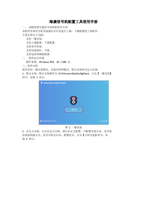
三、软件安装软件采用一键安装模式,安装有两种模式,默认安装和自定义安装:1、默认安装:默认安装路径为D:\Hikvision\DscConfigClient,点击【一键安装】即可,如图1 所示:图 1 一键安装2、自定义安装:点击自定义安装,弹出自定义配置,可配置安装目录、是否添加桌面快捷方式、是否开机自启动,配置好后,点击【立即安装】即可,如图2 所示:图 2 自定义安装四、通信配置(一)监听1、开启监听,等待信号机设备连接配置工具,监听界面如图3 所示:图 3 监听2、选择IP 地址,填写端口后,点击【监听】,等待设备连接,如图4 所示:3、图 4 正在监听(二)选择待配置设备当有设备连接后,连接的信号机信息会在待配置信号机列表中展示,如下图5 所示(信号机10.10.117.30 已连接到配置工具),多个信号机可手动切换;图 5 已有信号机设备连接到配置工具当有信号机设备连接后,会自动跳转到设备配置界面,界面左侧为设备配置项:设备信息、基本信息、灯组信息、相位信息、相位阶段信息、方案信息、日计划、调度表、安全信息、过渡约束、单元配置,如图6 所示:图 6 设备配置五、设备配置(一)设备信息设备信息中包括基础信息、设备校时、命令管道、设备升级等模块,以上模块均需要单独上载(获取)/下载(设置)。
1. 设备校时获取:可以获取信号机设备当前时间;设置:有两种方式,一种是自己配置时间,将配置好的时间设置给当前信号机设备;另一种是勾选“与计算机时间同步”,再设置,则设置的是当前计算机时间,如图7、图8 所示:图7 设备校时图8 通过日历设置时间2. 命令管道手动下载黄闪、全红、重启、开灯、关灯等命令,如图9 所示:图9 命令选项图10 设备升级(二)基本信息基本信息需要单独上载、下载,如图11 所示:图11 基本信息(三)灯组信息灯组是指一个完整的车辆红、黄、绿三头灯或行人红绿两头灯的组合,信号灯组对应一个相位的输出。
城市道路违法停车自动抓拍系统解决方案
城市道路违法停车自动抓拍系统解决方案杭州海康威视系统技术有限公司2013年12月阅读提示杭州海康威视系统技术有限公司公司总部:杭州市滨江区东流路700号客服热线: 400-700-5998网址: 目录第1章概述 (5)1.1 方案简介 (5)1.2 应用背景 (5)1.3 违法停车执法依据 (6)1.3.1 中华人民共和国道路交通安全法的相关规定 (6)1.3.2 中华人民共和国道路交通安全法实施条例的相关规定 (7)1.3.3 道路交通安全违法行为图像取证技术规范中的相关规定 (8)第2章总体设计 (10)2.1 建设思路 (10)2.2 设计原则 (10)2.3 设计依据 (12)2.4 设计目标 (13)2.5 系统架构 (13)2.6 系统组成 (14)2.6.1 自动跟踪球机 (14)2.6.2 视频分析记录仪 (15)2.6.3 中心管理系统 (15)2.7 工作流程 (16)2.8 系统功能 (18)2.8.1 违法停车自动取证功能 (18)2.8.2 支持手动取证功能 (19)2.8.3 多目标处理功能 (20)2.8.4 车牌自动识别功能 (20)2.8.5 多场景巡航取证功能 (21)2.8.6 取证图片多种合成方式 (22)2.8.7 图像防篡改功能 (23)2.8.8 查询统计及交通违法处理功能 (24)2.8.9 自动校时功能 (24)2.8.10 三码流输出方便视频存储调用 (24)2.8.11 支持录像存储及配额管理 (24)2.8.12 网络远程维护功能 (25)2.8.13 扩展前端声光报警提示及语言喊话功能 (25)2.9 系统性能 (25)2.10 设备参数 (26)2.10.1 自动跟踪球机(130万像素20倍变焦) (26)2.10.2 自动跟踪球机(130万像素30倍变焦) (29)2.10.3 自动跟踪球机(200万像素20倍变焦) (32)2.10.4 自动跟踪球机(200万像素30倍变焦) (34)2.10.5 视频分析记录仪(V AR-5004-F(2T)(D)) (37)第3章前端子系统设计 (39)3.1 前端子系统结构 (39)3.2 前端设备架设原则 (39)3.3 前端现场布局示意图 (40)第4章网络传输子系统设计 (41)4.1 网络传输子系统组成 (41)4.2 网络带宽需求 (41)第5章中心管理平台子系统设计 (42)5.1 平台概述 (42)5.2 中心平台结构设计 (42)5.2.1 平台主要设备、模块 (42)5.3 中心平台架设环境设计 (45)5.3.1 硬件环境及服务器参考配置方案 (46)5.3.2 软件环境 (49)5.3.3 网络环境 (49)5.4 平台功能设计 (50)5.4.1 控制管理功能 (50)5.4.2 配置管理功能 (53)5.4.3 资源信息获取功能 (57)第6章设备清单 (59)6.1 设备清单 (59)6.2 关于平台建设的说明 (60)第7章方案特点 (62)7.1 自动抓拍取证 (62)7.2 多场景巡航取证 (62)7.3 多目标处理功能 (62)7.4 可扩展混搭一体机视频电警 (62)7.5 环境适应性强 (62)7.6 超长延时抓拍 (63)7.7 自动查重处理 (63)第8章系统抓拍效果 (64)第1章概述1.1 方案简介本方案采用自动跟踪球机和视频分析记录仪相结合模式,对城市道路违法停车行为进行自动抓拍取证。
海康威视 IMS 4.0 客户端软件 用户手册说明书
IMS4.0客户端软件用户手册资料版本V2.0前言本部分内容的目的是确保用户通过本手册能够正确使用产品,以避免操作中的危险或财产损失。
在使用此产品之前,请认真阅读产品手册并妥善保存以备日后参考。
适用产品本手册适用于网络视频监控软件IMS4.0。
本手册描述了网络视频监控软件的使用,指导您完成网络视频监控软件的配置与操作。
硬件建议配置CPU:Intel(R)Core(TM)i56500@2.6GHZ或以上型号内存:4G或更高显卡:Intel HD630以上集成显卡或NVIDIA GTX750以上独立显卡网卡:千兆网卡或以上光驱:DVR-R硬盘:250G或以上,保证20G可用空间交换机:千兆交换机或以上软件要求1)windows764位系统、windows864位系统、windows1064位系统(不支持XP系统)2)Microsoft Visual C++2015X86Redistribuable Setup3)Microsoft Visual C++2015X64Redistribuable Setup系统环境程序运行需要占用554端口、11100端口、11110端口、11112端口、11114端口、11116端口、11118端口、11120端口、11122端口及11111端口,一台PC只能运行一个数据库,请确保没有其他数据库正在运行且这些数据端口未被占用,否则可能会导致程序无法正常运行。
目录IMS4.0客户端软件 (1)用户手册 (1)软件要求 (2)系统环境 (2)第一章安装和启动软件 (5)第二章设备管理 (6)2.1.添加区域 (6)2.2.修改区域 (7)2.3.删除区域 (8)2.4.搜索设备 (8)2.5.手动添加 (10)2.6.编辑设备 (11)2.7.删除设备 (11)第三章人员管理 (13)3.1.添加部门 (13)3.2.编辑部门 (14)3.3.删除部门 (15)3.4.添加人员 (16)3.5.编辑人员 (17)3.6.删除人员 (18)1.单人删除 (18)2.批量删除 (19)3.7.移动人员 (19)3.8.导入导出 (20)1批量导入 (20)2批量导出 (21)3.9.自定义属性 (21)第四章人员分配 (24)4.1.权限组管理 (24)4.2.设备管理 (24)4.3.人员管理 (26)第五章实时预览 (27)5.1.通道预览 (27)5.1.1.开启预览 (27)5.1.2.关闭预览 (29)5.2.布局轮巡 (31)5.3.通道对讲 (32)5.4.云台 (33)5.5.预览控制 (35)5.5.1.播放比例 (35)5.5.2.智能帧 (35)5.5.3.分屏 (36)5.5.4.抓拍 (38)5.5.5.全屏 (38)5.5.6.预览音频 (38)第六章录像回放 (39)6.1.录像计划 (39)6.2.录像查询 (39)6.3.录像播放及控制 (41)6.4.录像下载 (41)第七章人脸应用 (43)7.1.预览 (43)7.2.常规记录 (44)7.2.1.抓拍记录 (44)7.2.2.识别记录 (45)7.3.以图搜图 (46)第八章考勤管理 (47)8.1.基本规则 (47)8.2.考勤点管理 (48)8.3.班次管理 (48)8.4.考勤组管理 (50)8.5.节假日管理 (51)8.6.报表 (52)8.6.1.每日统计 (52)8.6.2.阶段汇总 (53)8.6.3.原始记录 (54)8.6.4.补卡记录 (55)第九章存储服务器 (57)9.1.服务器管理 (57)9.2.配额管理 (58)9.3.通道配置 (58)9.4.模板设置 (60)第十章用户管理 (61)第十一章联动规则 (62)11.1.事件类型 (62)11.2.联动动作 (63)第十二章事件中心 (65)12.1.实时告警 (65)12.2.事件查询 (66)第十三章日志管理 (68)第十四章系统设置 (69)14.1.功能配置 (69)14.2.声音配置 (69)14.3.图片路径 (70)第一章安装和启动软件操作步骤:(1)双击.exe安装文件,按向导完成安装。
海康综合监控与运维管理平台V13用户操作手册
min海康威视iVMS-9300综合监控与运维管理平台用户操作手册杭州海康威视系统技术有限公司2016.3目录目录 (1)第1章前言 (5)1.1编写目的 (5)1.2术语和缩写 (5)第2章平台概述 (6)2.1环境要求 (6)2.1.1运行硬件环境 (6)2.1.2运行软件环境 (6)2.2用户登录 (7)第3章运维概况 (7)3.1视频概况 (11)3.1.1视频概况 (11)3.1.2一键运维 (13)3.2卡口概况 (14)3.2.1过车统计 (15)3.2.2资源信息 (15)3.2.3服务器信息 (15)3.2.4最新异常信息 (16)第4章巡检中心 (16)4.1运行监测 (17)4.1.1监控点视频 (17)4.1.1.1 监控点明细查看 (17)4.1.1.2 视频预览 (18)4.1.1.3 工单上报 (19)4.1.1.4 视频质量诊断图片查看 (20)4.1.1.5 图像重巡 (21)4.1.1.6 查询导出 (21)4.1.2录像 (22)4.1.2.1 录像详情查看 (23)4.1.2.2 巡检一次 (24)4.1.2.3 工单上报 (24)4.1.2.4 查询导出 (25)4.1.3卡口 (26)4.1.3.1 卡口信息 (26)4.1.3.2 异常信息 (28)4.1.4编码资源 (29)4.1.4.1 设备详情查看 (30)4.1.4.2 工单上报 (31)4.1.4.3 查询导出 (31)4.1.5解码资源 (32)4.1.5.1 解码资源详情查看 (33)4.1.5.2 工单上报 (33)4.1.6视频服务 (35)4.1.6.1 服务详情查看 (35)4.1.6.2 工单上报 (36)4.1.6.3 查询导出 (37)4.1.7视频矩阵 (38)4.1.7.1 视频综合矩阵查看 (38)4.1.7.2 解码子系统 (39)4.1.7.3 编码子系统 (39)4.1.7.4 报警子系统 (39)4.1.7.5 码分子系统 (40)4.1.7.6 工单上报 (40)4.1.8智能机柜 (40)4.1.9业务树 (41)4.2可视监测 (42)4.2.1拓扑监测 (42)4.2.1.1 绘制拓扑图 (44)4.2.1.2 编辑栏介绍 (46)4.3告警查询 (47)4.3.1告警详情查看 (47)4.3.2解决告警 (48)4.3.3删除告警 (48)4.3.4创建工单 (49)4.3.5查询导出 (49)第5章资产管理 (50)5.1监控点资产 (50)5.2其他资产 (54)5.3资产统计 (57)第6章工单管理 (58)6.1待办工单 (58)6.1.1待审核 (59)6.1.1.1 查询导出 (60)6.1.1.2 工单处理 (60)6.1.1.3 工单驳回 (62)6.1.1.4 工单挂起 (65)6.1.2待反馈 (65)6.1.2.1 工单反馈 (66)6.1.2.2 查询导出 (67)6.1.3待确认 (67)6.1.3.1 维修审批 (68)6.1.3.2 延期审批 (69)6.1.3.3 查询导出 (69)6.2工单查询 (70)6.2.1综合查询 (70)6.2.2我创建的工单 (71)6.2.2.2 查询导出 (72)6.2.3已挂起工单 (73)6.2.1延期工单 (73)第7章统计报表 (74)7.1点位统计 (74)7.1.1监控点视频诊断统计 (74)7.1.2离线点位情况统计 (76)7.1.3历史离线时长统计 (76)7.1.4最近离线时长统计 (77)7.1.5区域运维考核统计 (77)7.1.6点位运行考核统计 (79)7.1.7经纬度考核统计 (79)7.2录像统计 (81)7.2.1区域录像情况统计 (81)7.2.2点位录像情况统计 (82)7.3工单统计 (82)7.3.1区域工单数量统计 (83)7.3.2人员工作数量统计 (83)7.3.3工单处理效率统计 (84)7.3.4工单处理及时统计 (84)7.4资产统计 (85)7.4.1区域资产数量统计 (85)第8章配置管理 (86)8.1巡检配置 (86)8.1.1采集器管理 (86)8.1.1.1 修改NMS采集器 (86)8.1.1.2 新增VQD采集器 (87)8.1.1.3 修改VQD采集器 (87)8.1.1.4 删除采集器 (87)8.1.2 NMS计划配置 (88)8.1.2.1 新增NMS采集计划 (88)8.1.2.2 修改NMS采集计划 (89)8.1.2.3 删除NMS采集计划 (89)8.1.2.4 启用采集计划 (90)8.1.2.5 禁用采集计划 (90)8.1.2.6 分配资源 (90)8.1.2.7 高级过滤 (91)8.1.3 VQD计划配置 (91)8.1.3.1 新增VQD采集计划 (91)8.1.3.2 修改VQD采集计划 (93)8.1.3.3 删除VQD采集计划 (93)8.1.3.4 启用采集计划 (94)8.1.3.5 禁用采集计划 (94)8.1.3.6 分配资源 (94)8.1.4告警阀值配置 (95)8.1.4.1 设备告警阀值配置 (95)8.1.4.2 编码设备和解码设备告警阀值配置 (95)8.1.4.3 监控点告警阀值配置 (96)8.1.4.4 视频综合平台和子系统告警阀值配置 (96)8.1.4.5 服务告警阀值配置 (97)8.1.5告警联动配置 (97)8.1.5.1 告警联动计划编辑 (98)8.1.5.2 查询 (99)8.1.6工单联动配置 (99)8.1.6.1 工单联动计划配置 (99)8.1.6.2 查询 (101)8.2资源配置 (101)8.2.1资源管理 (101)8.2.2组织树管理 (105)8.2.3业务树管理 (108)8.2.3.1 业务导航树 (108)8.2.3.2 资源列表 (110)8.3日志查询 (112)8.3.1操作日志 (112)8.3.2系统日志 (113)第9章系统配置 (114)9.1权限设置 (114)9.1.1用户管理 (114)9.1.1.1 同步单位信息 (114)9.1.1.2 同步用户信息 (114)9.1.1.3 批量设置角色 (115)9.1.1.4 批量取消角色 (116)9.1.2角色管理 (116)9.1.2.1 新增角色 (116)9.1.2.2 修改角色 (117)9.1.2.3 删除角色 (117)9.1.2.4 权限配置 (118)9.2基础设置 (118)9.2.1系统信息配置 (118)9.2.2字典管理 (119)9.2.2.1 新增字典 (119)9.2.2.2 修改字典 (119)9.2.3邮件配置 (120)9.2.4短信配置 (121)9.2.5密码强度扫描配置 (122)第1章前言1.1编写目的本用户手册的编写目的是帮助用户了解《iVMS9300综合监控与运维管理平台》,并学会对系统的操作。
- 1、下载文档前请自行甄别文档内容的完整性,平台不提供额外的编辑、内容补充、找答案等附加服务。
- 2、"仅部分预览"的文档,不可在线预览部分如存在完整性等问题,可反馈申请退款(可完整预览的文档不适用该条件!)。
- 3、如文档侵犯您的权益,请联系客服反馈,我们会尽快为您处理(人工客服工作时间:9:00-18:30)。
DSIS数字标牌软件应用解决方案2009-2011第1章DSIS数字标牌软件1.1.为什么使用DSIS数字标牌软件中国市场在高速发展,商业空前繁荣,消费者的水平快速提高,无论是在高档的社交场所,公共消费场所,还是企业内部区域的,都力求在营销、销售和服务手段提升一个层次。
系统能立即给企业经营带来先进、高档的品牌形象,直观生动地进行互动服务销售。
本公司在长期“企业-客户”互动营销服务研究的基础上,采取先进技术,结合金融行业业务特点,推出“总部集中管理制作,网点即时信息发布,并可生动地进行互动销售。
”的企业信息互动系统,帮助企业构建基于液晶电视,LED等数字多媒体统一业务互动营销管理平台。
系统注重功能完善性的同时,更注重实际应用优化,拥有便捷节目制作,绚丽播放效果,严谨权限管理,安全系统运行,强大系统扩展等功能特点。
银行为了实现基于“以客户为中心”的经营思路,秉承“智慧创造财富”的理念,依托控股金融产品门类齐全的优势,充分利用内部资源,为中高端客户提供的系列贵宾服务,满足客户个性化、多元化的金融需求。
为了给客户提供各种方便的信息服务,可通过在各营业厅部署液晶屏、等离子屏等多种显示终端,发布新产品、新业务广告,并实时显示人民币利率、外币利率、外汇牌价、外汇买卖、基金、债券、黄金、宣传用语、财经新闻等。
给顾客在享受工行提供特定业务的同时,也给顾客带来了其它方面的信息服务。
架起了银行和顾客之间的多媒体信息桥梁。
本项目基于上述理念,选用国内先进的数游DS多媒体发布终端及成熟的管理平台软件产品,布署一套独具特色的信息发布管理平台,一方面满足银行现有的业务部门的需求,另一方面为未来系统的扩展及维护打下基础。
数游DS多媒体信息发布系统针对工行营业厅的信息发布需求,以前瞻性、拓展性、先进性、实用性为设计思路,采取集中控制、统一管理的方式将视音频信号、图片和滚动字幕等多媒体信息通过网络平台传输到显示终端,以高品质的数字信号播出。
系统布署完成后,可实现省行统一管理全省的各营业厅所有的信息播放终端。
1.2 使用DSIS数字标牌软件会给客户带来怎样的好处?主要的好处有三点:提高效率、降低成本、提高营业收入。
具体的总结为以下三个方面:第一,帮助提高业务收入,通过客户接触点,传送更多的产品信息,包括促销信息、服务信息;第二,提高客户满意度;第三,提升品牌价值。
相关数据表明,使用DSIS数字标牌软件对于客户在品牌知名度、品牌影响力方面的贡献是巨大的,一般可以达到40%。
1.3 使用DSIS数字标牌软件的优势DSIS数字标牌是国内唯一实现一机多路异步输出的信息发布方案。
一台播放机可以实现两路异步LCD(TV),一路异步LED的集中控制。
从而,在保留现有硬件投入的情况下,可实现多种显示设备的统一管理。
具体指标如下:1、支持1080P的高清广告,而且支持多种编码格式2、24小时不停机,而且稳定、易维护、可中央统一管理,而且可以方便的和第三方数据对接。
3、支持一机多屏,比如:一个台主机两路显示输出,那么可以每块屏的不同播放内容4、可视化制作环境,所见及所得,可以在制作时就预览节目的播放效果5、多类型终端统一管理(目前支持singa、Windows、Android、同步LED、异步LED系统的播放终端)6、用户权限管理,每个用户分配不同功能模块的管理权限,允许为不同用户分配不同的终端设备,不同的素材目录、播出单目录和不同的频道目录。
7、支持互联网、有限/无限局域网等网络连接方式8、支持大视频U盘下发9、支持数据自动备份,系统数据灾难恢复。
1.4 安装前后的差别数游多媒体发布系统在“企业/产品展示、通知公告发布、导购促销海报等”领域的传统展现方式进行创新和变革,借助多媒体展示和网络化管理为企业在展示、销售、管理等方面体现非凡价值,以下是应用前后的对比:第2章系统应用2.1 应用场景系统在各地厂区、各办公区、连锁门店、专卖店、卖场专柜的户内及户外的应用,其应用包括液晶屏上的宣传、促销信息展示,液晶海报,现场销售演示(包括触摸屏上的销售展示),服务网点应用等。
具体描述如下:厂区、办公区:针对异地分布的企业,可通过此系统,即时将各类通知活动、内部指令等信息发布到特定厂区、办公或生产区。
营业厅门口:在店门口或店内放置一台LCD液晶屏,用来发布欢迎词、营业环境、产品介绍、最新活动等信息。
店内入口营销屏(或促销):在连锁店内可根据店面的大小在不同的地方放置2到3台液晶显示,每个液晶显示使用一台播放机。
用于连锁公司介绍、视频广告、促销信息、紧急通知等,让前来光临的客户对公司更加了解以及有一个轻松的好心情。
提高了整个连锁店的形象档次。
液晶海报:制作相关促销活动的液晶海报,通过液晶显示屏播放,可统一管理、实时更新液晶海报内容。
互动展示等:将需要展示的产品统一制作,客户来店,销售人员手按遥控器就能在液晶电视上生动演示产品,以及售后服务等,并可以直观地推动客户与产品的互动。
触摸屏:在连锁店内放置触摸屏或互动设备,将公司相关销售、服务网络、产品介绍以直观地展现形式实现与客户的互动。
客户体验中心液晶屏:模拟企业产品在实际应用环境下的客户体验,客户能够轻松的选择企业产品的不同型号在不同应用环境下的使用效果。
客户体验可应用在家居、家装、家电、厨卫等行业。
2.2 应用价值本系统为企业从信息展示、品牌提升、信息管理等几个方面带来价值。
●信息展示安装后,可将企业的形象宣传、产品介绍、内部新闻、通知公告等内容即时展现到各播放网点。
●品牌提升借助统一的宣传窗口、统一的节目内容、统一实时的节目更新,提升连锁企业整体品牌及认识度。
●连锁店(厂区、办公区)信息管理由总部统一、实时管理各连锁店(厂区、办公区)内的信息内容管理,针对不同的连锁店(厂区、办公区)可播放个性化的节目内容,无需重复制作光盘或文件,通过网络传输即可将个性化内容发布至各连锁店(厂区、办公区)。
●信息互动能够加强企业产品的信息通过互动方式实现客户对企业的产品体验,增加客户的互动趣味性。
并且能够将客户关注的产品或内容进行点击率或点播率统计,使营销部门及时掌握客户当前客户最为关注的要点。
连锁店(厂区、办公区)展示设备管理对连锁店内(厂区、办公区)展示设备,包括播放端电脑、液晶屏等设备进行监控和管理,及时了解各展示设备的状态,并且在总部即可关闭各连锁店(厂区、办公区)内的展示设备。
第3章系统功能DSIS数字标牌软件分发布管理端和播放端两个部分。
发布管理端主要是制作节目、制作日程、制作频道、管理播放端、上传素材等功能,播放端主要是部署节目、播放节目、现场查询服务等功能。
系统概要功能强大:本系统是本公司研发的,在大屏幕液晶和触摸屏上灵活组合视频、音频、动画,图片信息和字幕,向客户有效传递企业的营销、宣传信息,发布公告,促进互动。
对于欢迎信息、通知公告、内部新闻、产品介绍、天气预报、宣传资料、滚动字幕节目等即时信息可以做到立即发布,在第一时间将最新的资讯传递给受众群体,并根据不同区域和受众群体,做到分级分区管理,有针对性地发布信息。
易用:会用OFFICE就能使用系统。
系统非常便利地进行宣传内容的制作、发布和管理,方便、有效。
强大又方便的制作工具帮助企业的管理人员制作精美的宣传内容,可以通过网络自动发布到播放器,播放端按照计划时间播放,除了营销宣传、信息公告之外,还可以插播新闻、天气、日历、等信息。
典型物理部署图(一) 典型物理部署图(二)制作管理端:统一制作节目,根据权限分配,可修改、添加节目内容及更改播放列表,个性化宣传,发布各类通知、公告等重要信息;播放端:按照严格的时间表、播放列表、播放日程进行播放;网络平台:符合TCP/IP协议的网络(包括Internet、有线、无线、局域网)、专用内网等;硬件指标1、指令执行响应时间最小为1s2、支持节目资料断点续传3、视频加载时间:<1s4、运行时所占内存:<10%5、运行时所占CPU:<10%软件3.1 软件指标1、操作响应时间:<1s2、平均每秒钟响应次数:<13、100M网络环境,一台服务器可控制终端数:<=1004、并发下载连接数:>1005、单个视频资料大小:<4G3.2 节目管理✧系统灵活组合网页、视频、音频、动画,图片信息和字幕等信息;✧系统提供天气、时间、外汇、汇率等几十个节目元素组件,方便各类节目内容制作,并实现后台生产/业务系统数据库联接;✧屏幕区域可随意分割,实现各个区域显示不同的播放内容,所见即所得;✧系统自带大量模版可供客户选择,系统提供形象宣传、业务介绍、通知公告、安全提示、等几十余张模版,用户也可自行设计生成新的模板。
3.3 日程管理✧多元化的日程管理,目前支持(日,周,月,轮播)。
✧炫丽直观的日程设置界面,让用户更加直观的了解每天的日程。
✧自动纠错日程设置,对于错误的日程采用红色柱性提醒,让客户一目了然。
3.4 屏幕效果✧支持各种分辨率,有专业的视觉效果。
吸引客户的眼球。
✧支持多屏显示、平板显示、拼接屏显示墙、LED同步屏等多种显示设备。
✧支持立式竖屏播放。
3.5 屏幕监控✧对各播放端进行实时监控,采用实时状态监控及远程截屏有效结合的方式,确保播放内容准确安全。
✧实时网络连接状态、IP信息、播放端的状态、当前播放的节目,当前插播的消息,节目信息、播放端更新信息等。
✧播放端异常情况下,系统管理端自动报警提示,管理人员还可运程实时截取该屏幕显示画面。
3.6 素材管理✧支持视频格式:MPG、AVI、MPG、RMVB、MOV✧支持图像格式:JPG,PNG,GIF,SWF✧支持音频格式:DTS/AC3, MP3 MPEG1/MPEG2 MP3,WMA ✧支持流媒体协议:http, mms等实时流媒体协议✧支持PPT、Word、Excel3.7 权限管理✧账号管理:支持用户账号管理,设置各用户管理权限和初始化密码。
用户凭用户名和密码可进入系统管理端。
✧分组管理:可以对分布各个地区的网点进行分级、分区、分功能管理和授权管理。
✧权限管理:系统可以进行多级别管理,通过权限设定,最大程度上能满足企业分级应用,达到最优化管理流程。
✧审核管理:节目的制作后可设定一定的审核流程,只有经过审核的节目才可以发布。
3.8 扩展功能数游多媒体发布系统具有很强的可扩展性,留有多种硬件通信接口,可满足客户定制化需求及未来业务发展需要,可与企业生产管理系统、服务系统等多类系统对接,支持多种信息格式,并可融合管理网点原有的LED、液晶、离子等屏,从而避免网点设备重复投资,全面优化系统投资成本。
3.9 实时TV直播方案实施拓扑结构如下图所示:1、流媒体服务器需支持PCI插槽2、流媒体服务器需安装Windows encoding 和Windows meida Server,为播放端提供流媒体播放地址3、对Windows流媒体服务器有10-15秒延迟。