派利斯公司用户手册
派利斯中文使用手册
派利斯中文使用手册1. 简介1.1 派利斯是什么?- 定义:派利斯(Plis)是一款功能强大的项目管理软件,旨在帮助团队高效地协作和完成任务。
- 特点:a) 多人实时协作:多个用户可以同时编辑同一个项目,并即时查看对方的修改;b) 强大的任务管理功能:支持创建、分配、跟踪和更新各种类型的任务;c) 数据可视化展示:提供丰富而直观的图表与报告,便于监控项目进度。
2. 快速入门指南2.1 注册账号并登录系统步骤:a) 打开派利斯官网,在首页“注册”按钮;b) 填写必要信息(如用户名、密码等),然后“提交”按钮进行注册;c) 使用已注册好的用户名和密码登录系统。
3. 用户界面概述3.1 导航栏说明描述导航栏上每个选项所代表含义及其相应操作方法。
例如,“主页”用于返回到初始页面,“我的工作区”用于访问自己负责或参与过程中所有相关事务等。
4.新建项目流程详解解释如何创建一个新项目,包括以下步骤:a) “新建项目”按钮;b) 填写相关信息(如名称、描述等);c) 设定目标和里程碑;d) 添加团队成员并分配任务。
5.任务管理5.1 创建任务- 步骤:进入指定的项目页面,在左侧导航栏“添加任务”,填写必要信息后保存。
5.2 分配与跟踪任务- 描述如何将已创建的任务分派给特定用户,并实时追踪其完成情况。
6.数据可视化展示功能详解解释系统提供的各种图表与报告类型及其用途,例如甘特图、柱状图等。
7.常见问题解答提供一些经常遇到或可能出现的问题以及相应解决方法。
8.附件说明本文档涉及附件,请参阅所附文件列表进行查看和。
法律名词注释:- 派利斯:该术语在本文档中代表了软件产品Plis。
- 注册账号:此处指通过填写个人资料来获取使用权限。
- 导航栏:位于软件界面顶部水平排列显示多个选项卡式菜单条,方便用户快速切换功能模块。
- 任务:指项目中需要完成的具体工作或活动。
派利斯探头使用说明书

美国派利斯公司产品介绍—振动传感器系列美 国 派 利 斯 电 子 ( 北 京 ) 有 限 公 司北京朝阳区南磨房路37号华腾北搪商务大厦1905室邮编:100022电话:(010)5190-8800 传真:(010)5190-8761邮件: china@ 网址:1地震式探头选型指南美国派利斯公司产品介绍—振动传感器系列美 国 派 利 斯 电 子 ( 北 京 ) 有 限 公 司加速度传感器 TM0782A广泛应用于工业领域的压电晶体类型加速度传感器TM0782A-K 加速度传感器及套件由加速度探头和带5米电缆的接头组成。
TM0782A-K 加速度传感器及套件可以直接与派利斯公司的监测仪表连接,如DTM/TR 变送器、TM101变送保护表、PT580数字振动开关等,用于测量机壳振动,并输出加速度、速度、位移值。
技术参数电气指标灵敏度:100mV /g ±10%(25 oC ) 频响:0.5~10,000Hz (±3dB ) 最高振幅:50g 隔离:电路与外壳绝缘 噪声:0.0007g电源:2~10mA 恒流,18-30VDC 偏置电压:10 - 14VDC 共振频率:30kHz 最大传输距离:300米环境与物理指标温度区间:-50 oC ~+120 oC防护等级:IP67重量:90克 外壳材料:不锈钢 安装孔经:1/4-28UNF 安装力矩:29N*M 危险场合认证:ATEX : II 1 G, Ex ia IIC T4CSA : Class l, Div. 1, Groups A, B, C& D ,T4 PCEC :Ex ia IIC T4 GOST R: 0ExiallCT4X连接A :电源(红色电缆)B :公共端(白色电缆) COM :屏蔽层定货指南TM0782A-M加速度传感器(转接螺丝 1/4-28”→M6×1)TM0782A-E加速度传感器(转接螺丝 1/4-28” →1/4-28”)美国派利斯公司产品介绍—振动传感器系列美 国 派 利 斯 电 子 ( 北 京 ) 有 限 公 司北京朝阳区南磨房路37号华腾北搪商务大厦1905室邮编:100022电话:(010)5190-8800 传真:(010)5190-8761邮件: china@ 网址:3TM0782A-K-M加速度传感器套件包括: 9 TM0782A 加速度传感器 9转接螺丝(1/4-28” → M6×1) 9 TM0702-05TM0782A-K-E加速度传感器套件包括: 9 TM0782A 加速度传感器 9转接螺丝(1/4-28” →1/4-28”) 9 TM0702-05TM0782A-M-S9 加速度传感器(转接螺丝 1/4-28→M6×1) 9 本安防爆认证TM0782A-E-S9 加速度传感器(转接螺丝 1/4-28” →1/4-28”) 9 本安防爆认证TM0782A-K-M-S加速度传感器套件包括: 9 TM0782A 加速度传感器 9 转接螺丝(1/4-28″→M6×1)9TM0702-059 本安防爆认证 TM0782A-K-E-S加速度传感器套件包括: 9 TM0782A 加速度传感器9 转接螺丝(1/4-28″→1/4-28″)9TM0702-059 本安防爆认证.附件:(标准电缆长为 5 米, XX = 05) 建议选用 TM0702-XXTM0702-XX : MIL 铝插头, 带 XX 米电缆,直径7mm 。
TM202
电气指标:
外接电源: 22-30VDC,100mA,要求隔离电源; 90 - 250VAC ± 20% ,50 - 60Hz ,
输 出 灵 敏 度 : 8.0 mV/um (200 mV/mil); 电压输出范围:2-18V(非校验); 输出阻抗:100Ω。 最大传输距离:300 米。 总振动输出(4-20mA): 4-20mA,有源,可以驱动高达 750 Ω的负载; 1-5V,有源,输出阻抗 250Ω。 报警点设置(Normal/Set): 范围:0-100%满量程; 精确度:±0.1%。 线性范围:
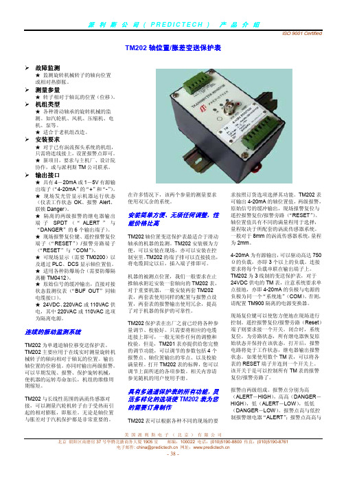
具有多通道保护表的所有功能,灵 活多样化的选项使 TM202 表为您 的需要订身制作
TM202 表可以根据各种不同的现场的要
求按照订货选项选择其功能。TM202 表 可输出 4-20mA 的轴位置值,两级报警, 原始信号的缓冲输出,现场报警复位与 遥控报警复位/报警旁路(“RESET”)。 轴位置值具有不同的满量程用于选择, 量程取决于所配套的涡流传感器系统。 一般对于 8mm 的涡流传感器系统,量程 为 2mm。
TM202 保护表在出厂之前已经将各种参 量调节、校验好。只需要将相应的电缆 连接上即可,一般无须作任何的调整和 校验。但是,TM201 表亦提供给您完整 的调节功能,可以调节的参数包括 4 个 报警点、轴位置输出的零点、以及校验 满量程。打开 TM202 表的标牌,您可以 调节上面所述的各项参数。相关内容请 参见随机的用户使用手册。
美国派利斯电子(北京)有限公司
北京 朝阳区南磨房 37 号华腾北搪商务大厦 1905 室 邮编:100022 电话:(010)5190-8800 传真:(010)5190-8761 电子邮件: china@ 网址:
- 39 -
SimpliFire SF-ALL48-BK 和 SF-ALL60-BK 产品说明书
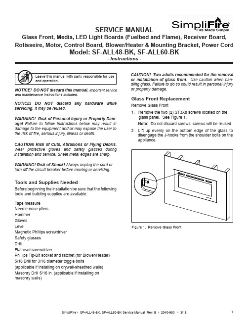
SERVICE MANUALGlass Front, Media, LED Light Boards (Fuelbed and Flame), Receiver Board, Rotisseire, Motor, Control Board, Blower/Heater & Mounting Bracket, Power CordCAUTION! Risk of Cuts, Abrasions or Flying Debris. Wear protective gloves and safety glasses duringinstallation and service. Sheet metal edges are sharp.NOTICE! DO NOT discard this manual. Important serviceand maintenance instructions included.NOTICE! DO NOT discard any hardware while servicing. It may be reused.WARNING! Risk of Shock! Always unplug the cord or turn off the circuit breaker before moving or servicing.Tools and Supplies NeededBefore beginning the installation be sure that the following tools and building supplies are available.Tape measure Needle-nose pliers Hammer Gloves LevelMagnetic Phillips screwdriver Safety glasses DrillFlathead screwdriverPhillips Tip-Bit socket and ratchet (for Blower/Heater)5/16 Drill for 3/16 diameter toggle bolts(applicable if installing on drywall-sheathed walls)Masonry Drill 5/16 in. (applicable if installing on masonry walls)Glass Front ReplacementRemove Glass Front1. Remove the two (2) ST3X8 screws located on theglass panel. See Figure 1. Note: Do not discard screws, screws will be reused. 2. Lift up evenly on the bottom edge of the glass to disengage the J-hooks from the shoulder bolts on the appliance.or property damage.Figure 1. Remove Glass FrontWARNING! Risk of Personal Injury or Property Dam-age! Failure to follow instructions below may result in damage to the equipment and or may expose the user to the risk of 昀椀re, serious injury, illness or death.Stone/Media Installation1. Remove Glass.2. Arrange the stone/media along the inset windowledge at the front of the appliance.Note: Extra media are provided and may bedistributed based on consumer preference. Not all media needs to be used.Glass Replacement (Continued)Installing Glass3. Install front panel. Locate the J-hooks on the back side of the glass on the four shoulder bolts on the appliance opening. Engage the shoulder bolts. See Figure 2.4. Press down on top edge of glass to fully engage J- hooks on the shoulder bolts.Note: Make sure the glass is fully attached to the 昀椀re-box so that the control panel can work properly.Figure 2. Glass Front Removal/Installation5. Thread the two (2) ST3X8 screws into the threaded holes on the glass panel. Check the alignment of the glass panel and securely tighten the screws. SeeFigure 3.Figure 3. Secure Glass Front1. Disconnect electrical service to the appliance. Forrecessed electrical installations that are hardwired,昀椀nd and shut-off service at the breaker. For wall-mounted installations that use a corded plug,disconnect the cord from the receptacle.2. Remove the glass front from the appliance. Use twopeople.3. Remove appliance the two screws in upper right andleft corners of the glass opening. Follow speci昀椀cinstructions from page 1 and 2 for removal of thefront glass. See Figure 4. CAUTION! Two adults recommended for the removal or installation of glass front. Use caution when han-dling glass. Failure to do so could result in personal injuryor property damage. Figure 4. Remove Upper Right & Left ScrewsPreparation for Component Installation4. Remove right and left side panels by turning thepanels inward. See Figure 5.Figure 5. Remove Right & Left Side Panels5. Using a 昀氀athead screwdriver, pry open the seventabs as shown in Figure 6. Pry the tabs upward at a30 degree angle. During this step, take care not toscratch or damage the glass panel behind the tabs.TABSFUELBED PLASTIC COVER Figure 6. Remove Plastic Cover6. Remove the fuelbed plastic cover that covers thefuelbed LED light strips. See Figure 6.LED Light Board InstallationThe LED Service Kit includes LED Light Boards for both the Fuelbed and the Flame effect.Determine which LED light set to be installed. See Figure 7.Figure 7. LED Light Board Identi昀椀cationLED FOR FUELBED1. Complete Steps 1-6 in Preparation for ComponentInstallation instructions. 2. Locate the Fuelbed LED Light Board cable. See Figure 8.LED LIGHT BOARD CABLE3. Unplug the LED Light Board cable. See Figure 9.LED LIGHT BOARD CABLEFigure 8. LED Light Board CableFigure 9. Unplug LED Light Board Cable4. Remove the LED light board from the bottom isolation columns. Starting at one end of the board use aLED FOR FLAMEFigure 10. Isolation Columns5. Remove and discard LED light board, replace with new LED light board. Install new LED light board by engaging the holes in the light board with the plastic barbs, and pressing into position. Reconnect the cables. See Figure 9.Fuelbed LED Light Board InstallationReceiver Board, Rotisseire, Motor, Flame LED Light Board, Control Board and Blower/ Heater Installation1. Complete Steps 1-6 in Preparation for ComponentInstallation instructions.3. Unplug Fuelbed LED Light Board, then lift it from theappliance set aside.Figure 12. Bracket Screw Location4. Remove seven (7) Phillips screws from the bracket. Remove the bracket. Set aside. See Figure 12.5. Carefully remove the glass panel. Rotate the top edge of the glass panel towards the opening, then lift out the the glass panel from the appliance. Set glass panel aside in a safe location, preferably a soft surface such as carpet or cardboard.Figure 11. Fuelbed LED Light Board Screw LocationReceiver Board Installation6. Locate the Receiver Board in the upper right side of appliance. See Figure 13.Figure 14. Receiver Board Cable7. Remove the Receiver Board from the isolationcolumns. Use a needle-nose pliers to compress the barbs on each isolation column.8. Unplug the cable, remove the Receiver Board and install with replacement board. See Figure 14.9. Reverse steps to complete installation.NOTE: The following steps (6-9) are only for re-placement of the Receiver Board.If replacing Rotisseire, Motor, Flame LED LightBoard, Control Board and/or Blower/Heater continue onto step 10.10. Remove two (2) Phillips screws at the bottom of the left and right side of the appliance opening. See11. Remove 14 Phillips screws at the top and bottom of the 昀氀ame screen. See Figure 16.12. Remove the 昀氀ame screen.Note: Be sure to place on a 昀氀at surface with the silk screen face-up. This is to prevent any distortion on the screen.13 Remove the center screw located in the the center of the Rotisseire. See Figure 17.14. Pull the Rotisseire to the left to disengage it from the motor, then remove the Rotisseire assembly.Figure 16. Flame Screen LocationFigure 17. Rotisseire Screw LocationIf replacing only the Rotisseire, install replacement part and reverse the installation steps.Be sure the 昀氀ame screen is installed correctly with the 昀氀ame silk screen to the outside and 昀氀ames at the bottom of the appliance.If replacing Motor continue to the next steps 15-18.Rotisseire InstallationIf replacing Flame LED Light Board continue to step 19.CAUTION! Risks of Cuts! Rotisseire has sharp edgesMotor InstallationThe motor is located in the lower right corner of the appliance.15. Remove the rubber shaft on the motor. See Figure 18.Figure 18. Rubber Shaft RemovalRUBBER SHAFT16. Remove the two screws on the motor. See Figure 19.Figure 19. Remove Motor Screws17. Unplug the motor cable connection. See Figure 20.Figure 20. Unplug Motor Cable18. Install replacement part and reverse the installation steps.Flame LED Light Board InstallationNOTE: The following steps (15-18) are only for re-placement of the motor.If replacing Flame LED Light Board, continue onto step 19.19. Remove screws used to attach the 昀氀ame screenFigure 21. Remove Flame Screen Bracket Screws.20. Remove 昀氀ame screen bracket.21. Unplug cable connection on each end of the LED Board. See Figure 22.Figure 22. Unplug LED Board Cable Connections22. Install replacement part and reverse the installation steps.Control Board Installation23. Remove the two (2) Phillips screws. After removing screws the mounting bracket can be lowered downto access the wires. See Figure 23.Figure 23. Remove Mounting Bracket Screws24. Unplug the 昀椀ve (5) pin and socket connectors between the Control Board and the wire harnesses. Tag and label the wire harnesses to ensure that wires will be reconnected correctly. See Figure 24.Figure 24. Unplug Control Board25. Install new Control Board and reverse the installation steps. Blower/Heater Installation26. Locate the four (4) screws on the mounting plate for the blower/heater module. See Figure 25.27. Remove the four (4) Phillips screws.Figure 25. Remove Mounting Plate Screws28. Drop the Blower/Heater module down on the shelf. See Figure 26.29. Reach up into the right end of the slot, and unplug the cable from the connector.Figure 26. Remove Blower/Heater30. Install new Blower/Heater and reverse the installationsteps.SHELFMasonry Wall •In the marked locations, drill 5/16 in. diameter x 2 in. deep holes. See Figure 30.• Insert the provided wall anchors into the holes. •Gently tap the anchors with a hammer until they are 昀氀ush with the wall surface.•With mounting hooks pointed up, attach the bracket to the masonry anchors with ST5X40 screws . SeeFigure 31.Figure 29. Installing Anchors in Hollow WallFigure 28. Toggle Bolt Installation through Mounting BracketFigure 30. Masonry Anchor PlacementFigure 27. 3/16 Toggle-Bolt Anchor•The toggle-bolt anchors are provided to accomodate the required anchor points based on the appliance. Use of toggle bolt anchors requires drywall thick-ness of minimum 1/2 in. and drilled holes size of 5/16 in. diameter.•Insert the bolt through the front side of the mounting bracket and thread the toggle onto it from the rear of the bracket. See Figure 28.•Fold the toggle wings 昀氀ush against the bolt and push them through a drilled hole until the toggle wings expand open on the other side. See Figure 29. •Pull back on the bolt and tighten. See Figure 29.Note: This product cannot be installed on a wall sheathed with drywall less than 1/2 in. thick, unless all six (6) anchor points in the mounting bracket align with structural framing members.WARNING! Risk of Damage or Personal Injury! Al-lowable pull-out and shear strength are 25% of ultimate values or less, as required by building authorities.Framed Wall •Locate the mounting bracket on the wall in thedesired location of the appliance. Level the bracket, then mark its location on the wall, including a mark-ing for each of the fastener holes in the bracket. •For each of the marked mounting point locations, determine which points align with a structural fram-ing member.•At the points where a wood or metal framing mem-ber exists, the ST5X40 screw can be installed directly into that structural member.•For every mounting hole that does not align with a structural framing member, a wall board toggle-bolt anchor must be used. See Figure 27.Direct Wall Mounting with Wall Mounting BracketThe wall mounting bracket can be installed on masonry walls such as those constructed of brick or concrete, or to framed walls constructed of wood or steel framing sheathed with gypsum wallboard, drywall, wood, etc. The method used to mount the mounting bracket is dif-ferent between masonry walls and framed walls. Refer to the following sections for more detail on the method applicable to this installation.11SimpliFire • SF-ALL48-BK, SF-ALL60-BK Service Manual Rev. B • 2040-960 • 3/18SimpliFire, a brand of Hearth & Home Technologies7571 215th Street West, Lakeville, MN 55044Please contact the SimpliFire customer/technical support hotline at 877-320-0730 with any questions or concerns.WARNING! Risk of Damage or Personal Injury! Do not use supplied masonry anchors on hollow walls,sheathed with wood, gypsum wallbaord, drywall or other materials.Figure 31. Bracket AttachmentWARNING! Risk of Fire, Electrical Shock and Injury! Ensure the power cord is not installed so that it is pinched or against a sharp edge and ensure that the power cord is stored or secure to avoid tripping and snagging.Power Cord Kit InstallationThe appliance power cord has a three pin NEMA-5-15P plug. The power cord should not be used unless a grounded receptacle is available.1. Remove the terminal block cover plate located on the right end of the appliance.2. Disconnect the terminal block from the three wires inside the appliance. Discard the terminal block cover plate.3. Connect the three appliance wires to the terminal block supplied with the power cord kit. See Figure 32.4. Replace cord kit terminal block cover plate and retaining screws. Plug cord into nearest outlet.Figure 32. Optional Power Cord Assembly InstallationLNR E DB L U EWire DiagramY E L L O W / G R E E N。
Parker Hannifin 产品说明:Pulsar VPL 非补偿方向控制阀说明书
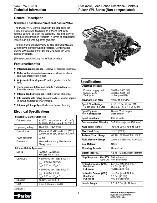
General DescriptionStackable, Load Sense Directional Control Valve The Pulsar VPL Series valve can be equipped for manual operation, hydraulic or electro-hydraulic remote control, or all three together. This flexibility of configuration provides freedom in terms of component location and plumbing arrangements.The non-compensated valve is fully interchangeable with today's compensated products. Combination stacks are available combining VPL with VP/VPO Series Products.(Please consult factory for further details.)Features/Benefits •Interchangeable spools Allows for reduced inventory.•Relief with anti-cavitation check Allows for shock and over pressure protection.•Adjustable flow stops Provides greater control of flow.•Three position detent and infinite friction lock Provides manual flow control.•Integral load sense logic Better circuit efficiency.•Intrinsically safe rating on solenoids May be applied in certain hazardous environments.•Internal pilot supply Reduces external plumbing. Electrical SpecificationsStandard & Marine SolenoidsCoil resistance12 VDC - 28.0 ohms at 21°C (70°F)24 VDC - 65.0 ohms at 21°C (70°F)Operating voltage12±3 VDC; 24±3 VDCCurrent draw430 mA at 12 VDC and 21°C (70°F)370 mA at 24 VDC and 21° C (70°F) PWM frequency33 HzConnectors WeatherPack (std.); Hirschmann,Flying LeadsIntrinsic Safety ApprovalsMSHA IA-627-0, IA-14238-0,XP Cert. No. 4111-0CENELEC NEMKO 90.114 - Eex ib IIA, T4,Imax= 300 mA, 12 VDC,L eq = 2.25 mH, Ceq= 0NEMKO 90.114 - Eex ib IIA, T4, Imax= 250 mA, 9 VDC,L eq = 2.25 mH, Ceq= 0NEMKO90.227 - Eex m II T4 CSA Class I, Groups C and D SpecificationsOperating PressurePressure supply port350 Bar (5000 PSI)Cylinder ports400 Bar (5800 PSI)Tank ports14 Bar (200 PSI)Maximum Inlet Flow190 LPM (50 GPM)Spool Flow Ratings6, 10, 17, 34, 53, 98 LPM15 Bar (220 PSI) Drop(1.5, 2.5, 4.5, 9, 14, 26 GPM) Spool/Cylinder Closed, Vented-open,Port Configuration Open (motor)Spool Deadband25% of strokeRecommended Filtration SAE Class 5 (17/14-ISO 4406) Fluid Temp. Range-40°C to 90°C (-40°F to 195°F) Max. Fluid Temp.121°C (250°F)Ambient Temp. Range-40°C to 88°C (-40°F to 190°F) Fluid Viscosity Range323 to 1.1 cSt (1500 to 30 SUS) Seal Material NitrileMounting Attitude UnrestrictedWeight (approx.) 4.5 kg (10.0 lbs.) work segment Step Response:0%-100%300 milliseconds100%-0%150 millisecondsHydraulic Control (VWL)24.1 Bar (350 PSI) PilotDeadband 5.5 Bar (80 PSI)Fullstroke15.2Bar (220 PSI)Hydraulic Control (VKL)14.5 Bar (210 PSI) PilotDeadband 3.5 Bar (50 PSI)Fullstroke10.3 Bar (150 PSI)Handle Torque0.6 - 2.5 Nm (5 - 22 lb/in)Code Description0None (VWL, VKL, VML only)112 V Pulsar, 12” flying leads312 V Pulsar with Weather Pack connector, 12” leads 524 V Pulsar, 12” flying leads724 V Pulsar with Weather Pack connector, 12” leads A 12 V Marine (Nemko), 100” flying leads B 24 V Marine (Nemko), 100” flying leadsJ 12 V Hirschmann, Large (DIN 43 - GDM Series)K 24 V Hirschmann, Large (DIN 43 - GDM Series)L 12 V Hirschmann, Small (G Series)M 24 V Hirschmann, Small (G Series)N 12 V Pulsar with 36” flying leadsP 12 V Pulsar with 36” leads, Weather Pack connector Q 24 V Pulsar with 36” flying leadsR 24 V Pulsar with 36” leads, Weather Pack connector S 11.2 V , Intrinsically safe w/male Electro connector T 11.2 V , Intrinsically safe w/Weather Pack connector X 12 V , XP Pulsar with male Electro connectorCode Description 2 2 way, C1 port 3 3 way, C1 port4 4 way, C1 and C2 portCode Description Q Electrohydraulic on-offP Electrohydraulic proportionalK Hydraulic remote (210 PSI pilot)W Hydraulic remote (350 PSI pilot)M Manual ControlCode DescriptionA 5.6 LPM (1.5 GPM)19.5 LPM (2.5 GPM)217.0 LPM (4.5 GPM)334.0 LPM (9.0 GPM)453.0 LPM (14.0 GPM)598.5 LPM (26.0 GPM)Note: For different flows Consult Factory.Code Description2Closed cylinder ports (CC)3C1 port (CC), C2 port (VOC)4Open cylinder ports (OC-Motor)7Vented open cylinder ports (VOC)Code Description1 2 pos. flow adjustment on C12 2 pos. no flow adjustments 3 3 pos. no flow adjustments4 3 pos. flow adjustments on C1 and C25 3 pos. flow adjustment on C1 only6 3 pos. flow adjustment on C2 only A 3 pos. Detent C1, C2 and CenterB Infinite position friction lock w/ center detentNote:Detent not available w/ flow adjustment option(Code A & B are VML only)Ordering Example:VQL5444-3035-26JOVValveSpool OperationLow Flow SectionSpool Flow RatingCylinder Port ConfigurationPilot ControlLSpool PositionsFlow DirectionsCode Description0Non-compensatedCode Description3Manual operator shaft only 4Manual operator with adapter and 6-inch handle 5Manual adapter only 6Marine handle adapter 7Marine handle adapter with 6-inch handleCode Description 4SAE ports 5BSPP portsCode Description 0No port cavity2Relief, with anticavitation check 3Anticavitation check5Float, 12 VDC or 24 VDC 6Defeat plugCode Pressure Setting A 50 Bar (750 PSI)B 63 Bar (950 PSI)C 80 Bar 1150 PSI)D 100 Bar (1450 PSI)F 125 Bar (1850 PSI)G 140 Bar (2050 PSI)H 160 Bar (2350 PSI)J 175 Bar (2550 PSI)K 190 Bar (2750 PSI)L 210 Bar (3050 PSI)M 230 Bar (3350 PSI)N 250 Bar (3650 PSI)P 280 Bar (4050 PSI)R 300 Bar (4350 PSI)S 320 Bar (4650 PSI)T 350 Bar (5050 PSI)O N/ACode Description 0No port cavity2Relief, with anticavitation check 3Anticavitation check5Float, 12 VDC or 24 VDC 6Defeat plug 0Section Pressure CompensatorManual OverrideDesign LevelC1Cylinder Port Option C2Cylinder Port OptionC2 PressureC1 PressureBulletin HY14-2101/US,3M, 9/02, PHDParker Hannifin Corporation Hydraulic Valve Division 520 Ternes AvenueElyria, Ohio, USA 44035Tel:(440) 366-5200FAILURE OR IMPROPER SELECTION OR IMPROPER USE OF THE PRODUCTS AND/OR SYSTEMS DESCRIBED HEREIN OR RELATED ITEMS CAN CAUSE DEATH, PERSONAL INJURY AND PROPERTY DAMAGE.This document and other information from Parker Hannifin Corporation, its subsidiaries and authorized distributors provide product and/or system options for further investigation by users having technical expertise.It is important that you analyze all aspects of your application and review the information concerning the product or system in the current product catalog. Due to the variety of operating conditions and applications for these products or systems, the user, through its own analysis and testing, is solely responsible for making the final selection of the products and systems and assuring that all performance, safety and warning requirements of the application are met.The products described herein, including without limitation, product features, specifications, designs, availability and pricing, are subject to change by Parker Hannifin Corporation and its subsidiaries at any time without notice.WARNINGPressure Drop C 1/C 2 ➔T (Meter Out Spools)Segment Flow vs.Load PressureWith Pressure Compensated Bypass Inlet (225 PSID)(Excess Flow can be limited with Spool Stroke Adjustment if required)Note:The flow rates for all spools will increase by 2 to 3% for every 10 PSI increasein differential pressure drop from the pump supply port to the load sensing port.All OptionsManual Control VMLPsC2L.S.C1TTRelief with AnticavitationAnticavitation CheckDigital PulsarDigital PulsarFlow Adjustment ScrewsLoad Sense Shuttle NetworkInterchangeable Spools6”Manual OperatorHydraulic Remote Control –VWL/VMLThe items described in this document are hereby offered for sale by Parker Hannifin Corporation, its subsidiaries or its authorized distributors. This offer and its acceptance are governed by the provisions stated in the "Offer of Sale".Offer of Sale。
派利斯中文使用手册

派利斯中文使用手册第一章:介绍派利斯是一种强大的翻译工具,可以帮助用户实时翻译各种语言。
本手册将向您介绍派利斯的基本功能和使用方法。
第二章:安装和登录3.注册成功后,使用您的账户信息登录派利斯。
第三章:主要功能1.实时翻译:打开派利斯应用程序后,在输入框中输入您要翻译的文字或语句。
选择源语言和目标语言,然后点击“翻译”按钮即可实时翻译。
3.语音翻译:选择“语音翻译”功能。
按住录音按钮,说出要翻译的语句,松开按钮。
派利斯将尝试将语音转化为文字,并进行翻译。
第四章:高级功能3.字典功能:在派利斯应用程序中,选择“字典”功能。
输入要查询的单词或词组,派利斯将提供释义和示例用法。
第五章:常见问题1.为什么翻译结果不准确?派利斯尽力提供准确的翻译,但由于语言的复杂性和多义性,翻译结果可能存在误差。
2.如何提升翻译准确度?可以参考翻译结果的上下文,或尝试将长句拆分为更简洁的表达方式进行翻译。
第六章:使用技巧1.精确翻译:尽量提供清晰、准确的输入文本,以获取更准确的翻译结果。
2.听写模式:选择“语音翻译”功能后,点击“听写”按钮。
派利斯将在最终翻译前提供一段时间供您确认听写结果是否准确。
3.手写输入:在选择源语言后,可以通过点击键盘按钮来切换到手写输入模式,然后使用手指书写字母和汉字。
第七章:常用短语1.问候和礼节用语2.旅行用语3.饮食用语第八章:常用表达1.感谢与道歉2.询问与告知3.请求与回答第九章:技术支持本手册为派利斯中文使用手册,介绍了派利斯的基本功能、高级功能、常见问题、使用技巧以及常用短语和表达等内容。
希望通过本手册,用户能够更好地使用派利斯进行准确、便捷的翻译。
LPS505N英文说明书(苏州顺测电子)

LPS 505N Programmable DC Power Supply User’s ManualLegal NoticesLegal NoticesThe information in this document is subject to change without notice. MOTECH makes no warranty of any kind with regard to this manual, including, but not limited to, the implied warranties of merchantability and fitness for a particular purpose. MOTECH shall not be held liable for errors contained herein or direct, indirect, special, incidental or consequential damages in connection with the furnishing, performance, or use of this material. MOTECH INDUSTRIES INC. 6F, No. 248, Sec. 3, Pei-Shen Road, Shen-Keng Hsiang, Taipei Hsien, 222, Taiwan Copyright Notices. Copyright 2005 MOTECH, all rights reserved. Reproduction, adaptation, or translation of this document without prior written permission is prohibited, except as allowed under the copyright laws.WarrantyWarrantyAll MOTECH instruments are warranted against defects in material and workmanship for a period of one year after date of shipment. MOTECH agrees to repair or replace any assembly or component found to be defective, under normal use during this period. MOTECH's obligation under this warranty is limited solely to repairing any such instrument, which in MOTECH's sole opinion proves to be defective within the scope of the warranty when returned to the factory or to an authorized service center. Transportation to the factory or service center is to be prepaid by purchaser. Shipment should not be made without prior authorization by MOTECH. This warranty does not apply to any products repaired or altered by persons not authorized by MOTECH, or not in accordance with instructions furnished by MOTECH. If the instrument is defective as a result of misuse, improper repair, or abnormal conditions or operations, repairs will be billed at cost. MOTECH assumes no responsibility for its product being used in a hazardous or dangerous manner either alone or in conjunction with other equipment. High voltage used in some instruments may be dangerous if misused. Special disclaimers apply to these instruments. MOTECH assumes no liability for secondary charges or consequential damages and in any event, MOTECH's liability for breach of warranty under any contract or otherwise, shall not exceed the purchase price of the specific instrument shipped and against which a claim is made. Any recommendations made by MOTECH for use of its products are based upon tests believed to be reliable, but MOTECH makes no warranty of the results to be obtained. This warranty is in lieu of all other warranties, expressed or implied, and no representative or person is authorized to represent or assume for MOTECH any liability in connection with the sale of our products other than set forth herein. MOTECH INDUSTRIES INC. 6F, No. 248, Sec. 3, Pei-Shen Road, Shen-Keng Hsiang, Taipei Hsien, 222, Taiwan Telephone : (886-2) 2662-5093 Facsimile : (886-2) 2662-5097 Email : instrument@ URL : Storage. Freight. Maintenance. Disposal※※※ Storage. Freight. Maintenance. Disposal ※※※Storage When don’t use the device, please pack it properly and store under a good environment. (The packing is no needed when the device under appropriate environment.) Freight Please use the original packing material when move the device. If the packing material is missing, please use the equivalent buffer material to pack and mark it fragile and waterproof to avoid the device damage during movement. And, please avoid heavy hitting to damage the device. Maintenance There is no maintenance operation for the general user (except for the note in the manual). Please contact our company or agent when the device occurred the user judgment abnormal. Don’t maintain by yourself to avoid occurred unnecessary danger and serious damage to the device. Disposal When the device in badly condition and can’t be used or repaired, please discard it according to your company disposal procedures or local legal procedures. Don’t discard arbitrary to avoid polluting environment. The device is precision equipment, please use qualified transportation as possible.IndexIndex1. Introduction ....................................................................................................1-1 1.1 1.2 2. 3. An Overview of Product ......................................................................1-1 Features..............................................................................................1-1Specification ...................................................................................................2-1 Notices before Using .....................................................................................3-3 3.1 Confirm Attachment before Using .......................................................3-3 3.2 3.3 3.4 3.5 3.6 3.7 3.8 The Description of Using.....................................................................3-3 Ambient Environment..........................................................................3-3 Storage ...............................................................................................3-3 Power-Line Voltage.............................................................................3-4 Fuse....................................................................................................3-4 Warming Up ........................................................................................3-4 End Test ..............................................................................................3-4 LPS 505N Panel Description ..............................................................4-1 Front Panel Description ......................................................................4-1 Rear Panel Description .......................................................................4-9 Voltage Setting....................................................................................5-1 Current Setting....................................................................................5-1 OVP ....................................................................................................5-1 OCP ....................................................................................................5-2 Rotary Controller (output on)...............................................................5-2 Preface ...............................................................................................6-1 Definition of Parameters .....................................................................6-1 Error/Event Queue ..............................................................................6-1 Compatible MOTECH LPS and PPS Protocol ....................................6-4 SCPI Compatiable Information............................................................6-9 SCPI Frequent Command...................................................................6-9 SCPI Command for Subsystem ........................................................6-10 Rules of Status Definition..................................................................6-314.Panel Description ...........................................................................................4-1 4.1 4.1.1 4.1.25.Operation Setting ...........................................................................................5-1 5.1 5.2 5.3 5.4 5.56.Remote Interface Protocol and Package Mode............................................6-1 6.1 6.2 6.3 6.4 6.5 6.5.1 6.5.2 6.67.Accessories ....................................................................................................7-1Introduction1. Introduction1.1 An Overview of ProductMotech LPS 505N is a triple outputs and programming DC power supply. LPS 505N comes with 12 bits resolution. Total 222W power output is provided by triple independent outputs. Double output provide 0~32V/3A, the other one provides 0~15V/5A 30W. For the 0~15V/5A output, users can use auto-ranging while constant 30W power output. This is the unique feature and it differs from other traditional power supplies. Those two 0~32V/3A outputs are required to output in serial or parallel mode. Tracking function is convenient and changeable for users in circuit application. LPS 505N has rotary and number key for user to easily operation. The configuration can be stored in memory (Max.100). Timer (1 sec~100 hrs) control when output can be switched off. It can provide the safety for burning room and electroplating application. OVP, OCP can be controlled and monitored by front panel. Users will not change the original setting because of the key lock function. When source and load change, LPS 505N has stable output due to 0.01% load and line regulation and max. 50 us respond time. Average measurement time is 50 ms to increase the production quantity.1.2 Features1. Triple output: Voltage Ranges : 0 ~ 32V (CH1&CH2) / 0 ~ 15V (CH3) Current Ranges : 0 ~ 3A (CH1&CH2) / 0 ~ 5A (CH3) Power Ranges : 0 ~ 96W (CH1&CH2) / 0 ~ 30W (CH3) The third output is an auto-ranging output. Users can change voltage and current as they want based on maximum 30W output. For example, output 15V/2A or 6V/5A voltage and current should be within the output range. 2. Digital rotary, number key, function key setting: Digital rotary can change voltage rapidly. Simulate the surge of the voltage output. It provides the solution for the trigger circuit testing. User can set up voltage by number key quickly. It differs from original VR adjusting. Function key provide users operation more friendly and easily. 3. Precious measurement on voltage & current: Besides precise output, LPS 505N provides voltage and current measurement.1-1IntroductionUsers can reduce the measurement equipment budget and space. 4. Memory and timer function: LPS 505N has large memory to memorize 100 settings. Operators are unnecessary to remember the settings. It can be easily to recall the settings. For safety issue, timer function will automatically switch off the machine when they are burning in burning room. LPS 505N can also provides time control good current resolution for electroplate application as customers’ need. 5. OVP, OCP & lock protection function: OVP, OCP provide the safety for the laboratory. The setting will not be changed due to the key lock function. 6. Series, parallel mode: In serial mode, CH1/CH2 can output maximum 64V with positive/negative output. It can be used for OP circuit design. In parallel mode, CH1/CH2 can output 6A maximum. 7. Dual tracking: Users only needs to setup CH1 output voltage and current, LPS 505N will output the same voltage/current at CH2. This is convenient to test two samples at the same time.1-2Specification2. SpecificationModel LPS 505NChannel NO. CH1 & CH2 CH3Output Voltage 0~32V 0~15V Output Current 0~3A 0~5AOutput Power96W 30W(CH3 Auto Ranging)Line Regulation ±(% of output +offset)Voltage 0.01% + 2mVCurrent 0.01% + 300uALoad Regulation ±(% of output +offset)Voltage ≦3mV ≦5mV Current 0.01% + 300uARipple and Noise ( 20Hz ~20MHz )Normal Mode Voltage 700uVrms / 7mVpp 1mVrms / 20mVpp Normal Mode Current <1mA <5mA ResolutionProgramming 10mV / 1mA 10mV / 2mA Readback 10mV / 1mA 3mV / 2mA Programming Accuracy ±(% output +offset)Voltage 0.05% + 20mV 0.05% + 6mV Current 0.05% + 3mA 0.05% + 4mA Readback Accuracy ±(% output +offset)Voltage 0.05% + 20mV 0.05% + 6mV Current 0.05% + 3mA 0.05% + 4mA Temperature Coefficient per℃ ±(% output +offset)Voltage <0.1% + 3mVCurrent <0.2% + 2mATracking Accuracy ±(% of output +offset)Voltage 0.1% + 40mVTransient Response Time <50uSStability﹐constant output & temperature ±(% of output +offset)﹐8hrs Voltage <0.2% + 2mVCurrent <0.1% + 1mASpecificationVoltage Programming SpeedRising Time at Full Load 3mSecRising Time at No Load 3mSecFalling Time at Full Load 8mSecFalling Time at No Load 250mSecGeneralAC Line Input VoltageRanges115/220 VAC ± 10%(50/60Hz)Temperature Ratings Operating( 0°C ~40°C),Storage (- 10°C ~70°C)Common-Mode Voltage ±240Vdc Dimensions ( W×H×D )mm (216 × 135 × 432 )Weight 6.5 kgLPS 505N Features:LCD display, triple independent output and display on LCDCH3 auto-ranging outputLow Ripple, Low NoiseNumber and function keyStore and recall settings (100)Timer (1 sec ~100 hours)Precise voltage and current measurementOVP, OCP and key lockSerial and parallel modeDual Tracking ModeAverage measurement time 50m secStandard RS232, USB interfaceNotices before Using3. Notices before Using3.1 Confirm Attachment before UsingPlease follows the below items to protect your rights as you receive this instrument.1. If there is ruin or scratch bad condition on product overlook.2. The standard attachment as table 7-1, please confirm if there is any missing.※If above conditions, please inform us for prompt service.3.2 The Description of UsingThe tester is an accurate instrument. Please read through this manual to prevent improper operation and arbitary using from causing this instrument damaged. Please calibrate once a year for keeping accuracy.3.3 Ambient Environment1. Do not use the tester in a dusty, vibrating, sunlight and corrosive gas. Pleaseuse this instrument under the ambient temperature is 0~40°C and the relative humidity is 20%~80%. If the temperature is over 40°C, please don’t use temporary until the temperature is down to normal. Please check to avoid the unit damage which result from over temperature.2. The tester is equipped with a cooling fan on the rear panel to keep the internaltemperature down, so adequate ventilation should be ensured. The tester should be located at least 10cm from any object or wall behind it. Do not block the ventilation holes to keep the tester in good precision.3. The tester has been carefully designed to prevent the noise from the AC powersource. However, it should be used in the noise-free environment as low as possible. If noise is inevitable, please install a power filter.3.4 StorageThe tester should be stored within the temperature range -10°C ~ 70°C, the relative humidity 80% RH. If the unit is not to be in use for a long time, please store it in the original or similar package and keep it from direct sunlight and humidity.Notices before Using3.5 Power-Line VoltageThe tester is an instrument which uses AC power 115V/220V 50Hz/60Hz. Before plugging in the power cord, make sure the power switch is in the off position and the voltage of the rear panel is the same as the required voltage.3.6 FuseThere is one fuse installed in the rear panel. When replacing the fuse, please notice the following:1. Please turn off the power and disconnect the AC power cord and all the otherconnections to the power supply.2. The checking of fuse can’t sure with the eyes, the testing value under 15Ωisnormal.3. When replacing the fuse, the cap jut out the rear panel on fuse stand using flattype screwdriver or pressing softly by hand.Mark Center Voltage Range Fuse115 115V 100V~125V Slow220 220V 200V~250V SlowWarning:For continues protection against fire hazard, replace only with thesame type and rating of fuse as specified.3.7 Warming UpThis tester activates at power on. However, in order to meet the accuracy in the specification, please warm it up for 30 minutes or longer.3.8 End TestWhen tests are done and the tester is not in use or need to leave for a while during usage, make sure to turn off the power switch.Panel Description4. Panel Description4.1 LPS 505N Panel Description4.1.1 Front Panel Description(1) Display:Display is a 20x4 yellow green backlight LCD(2) Rotary(ENTER):Rotary can adjust voltage and current. Users can press it as ENTERfunction.(3) M:Press M key to memory configuration display. Users can select whichsetting to store and recall by pressing STORE and RECALL key.(4) CH:Selecting CH1/CH2/CH3Panel Description(5) ON/OFF:Switching power output on or off of the instrument(6) Number Key:Input number by number key. To set the voltage or current, press the“V” or “A” key after the number input.(7) ►(STORE):When the output is on, press the key to move the cursor to select digitfor adjustment. Users can adjust the digit by rotary. In memory function,store into memory by pressing this key.(8) ◄(RECALL):When the output is on, press the key to move the cursor to select digitfor adjustment. Users can adjust the digit by rotary. In memory function,recall from the memory by pressing this key.(9) DISP:Press this key to select the display to show the voltage/current orpower/resistance readout.(10) V(Voltage):Press this key to set voltage after number input.(11) A(Current):Press this key to set current after number input.(12) Config:Press this key to enter the configuration setting. There 16 items to beset in this mode.1. Timer: The initial value is OFF. Press the rotary to enter timerconfiguration.Panel DescriptionA. Using rotary or ◄►to move the cursor onto the digit and input thenumber. Timer: 00:00:00 (HH:MM:SS)B. Switching CH1/CH2/CH3 by press CH key. Then press rotary toswitch ON/OFFC. Start Timer when press ON/OFF keyD. Press rotary + CLEAR to pause the timer. Restart by repeating thesame step2. TRACKING: The initial value is OFF, switch to ON by pressing therotary. The CH2 will have the same voltage and currentsetting as the CH1.3. OVP setting: Over voltage protection. Press the rotary to enter OVPConfiguration. Press “CH” to select CH1/CH2/CH3.Users can press ON/OFF to enable or disable OVP andinput the voltage value via the number keys. Pleaseremember to press rotary to save the settings.Panel Description4. OCP setting: Over current protection. Press rotary to enter OCPConfiguration. Press “CH” to select CH1/CH2/CH3.Users can press ON/OFF to enable or disable OCP andinput current value via the number keys. Pleaseremember to press rotary to save the settings.5. Baud rate: Transmission speed. Users can select baud rate for 1200,2400, 4800, 9600, 19200, 38400 by rotary.6. Interface: Transmission interface. Users can select RS232, USB,GPIB (Optional), LAN Port (Optional) by using rotary.Panel Description7. DHCP:This parameter is for LAN port setting. The default value is Offmode. You may change the mode by press the rotary. AtDHCP "On" mode, a dynamic IP address can be obtainedfrom the server.8. IP***.***.***.***:Setting of IP address. You may key-inthe right IP address for PPS 3210。
工作文档SPPA-T3000用户手册(组态手册3)

sSPPA-T3000,用户手册用户组态手册(共4册,第3分册)目,录1,,模板编辑器.................... 错误!未指定书签。
1.1,,启动模板编辑器 ...... 错误!未指定书签。
1.1.1,,退出模板编辑器.. 错误!未指定书签。
1.2,,常规布置................. 错误!未指定书签。
1.2.1,,工具栏.................. 错误!未指定书签。
1.2.1.1,,标准............... 错误!未指定书签。
1.2.1.2,,链接............... 错误!未指定书签。
1.2.1.3,,排列............... 错误!未指定书签。
1.2.1.4,,图形布局....... 错误!未指定书签。
1.2.1.5,,交互式绘图工具错误!未指定书签。
1.2.2,,模板的上下文菜单错误!未指定书签。
1.2.3,,单一、持久模式.. 错误!未指定书签。
1.2.4,,选项...................... 错误!未指定书签。
1.2.5,,窗口...................... 错误!未指定书签。
1.2.6,,保存视图.............. 错误!未指定书签。
1.3,,模板功能................. 错误!未指定书签。
1.3.1,,保存模板.............. 错误!未指定书签。
1.3.2,,以新的名字保存模板错误!未指定书签。
1.3.3,,打开库.................. 错误!未指定书签。
1.3.4,,编辑模板.............. 错误!未指定书签。
1.3.5,,创建新的模板...... 错误!未指定书签。
1.3.6,,删除模板.............. 错误!未指定书签。
1.3.7,,删除模板库节点.. 错误!未指定书签。
1.3.8,,将模板移动到另一个库节点错误!未指定书签。
- 1、下载文档前请自行甄别文档内容的完整性,平台不提供额外的编辑、内容补充、找答案等附加服务。
- 2、"仅部分预览"的文档,不可在线预览部分如存在完整性等问题,可反馈申请退款(可完整预览的文档不适用该条件!)。
- 3、如文档侵犯您的权益,请联系客服反馈,我们会尽快为您处理(人工客服工作时间:9:00-18:30)。
4 16=20-4; 5 根据用户需要而定; 6 根据仪表参数而定,现场不能更改;
¾ 探头的安装 ¾ 和各仪表元件之间的正确接线 2) 探头的安装(参见涡流探头的安装)
派利斯电子(北京)有限公司产品用户手册
3)正确接线 (参照 TM202 现场接线图)
TM0200; or PLC, Remore
DCS
Reset
延长电缆
POW
前置器 COM
SIG
8mm涡流探头 转子
TO ALERT
SPAN
1.取下监测表角上的四个螺钉。 2.连接前置器、延长电缆和涡流传感器,使传感器接近被测物体, 保持涡流探头与被测物
体的静态间距为 0.8mm. 3.卸下前面板上的四个螺钉。. 4.在振动台静态时,调节 “ZERO”钮 直到 “4-20mA ”输出显示 4.00mA. 5.将振动台的振动调至最大调节检 测右下脚的“SPAN”, 直到“ 4-20mA ”输出显示为
报警值电流读数=4+16×12/50=7.84mA 连锁值电流读数=4+16×25/50=12.0mA
本指南适用于TM202、TM302。
对于TM表的现场调试仅限于设置 零位(Zero)、报警(Alert)、连锁(Danger)值 的更改与设定,其它操作必须经过派利斯公司同意方可进行! 调试步骤如下: 1. 正确接线; 2. 卸下 TM 表上的小标牌(印有技术参数的白色小标牌); 3. 按照下图对照进行操作:
派利斯电子(北京)有限公司产品用户手册
6、TM201 单通道振动保护表探头安装指南
1) 安装步骤: TM201 单通道保护表的安装一般分两大步骤:
¾ 探头的安装 ¾ 各仪表元件之间的正确接线
TM0200; or PLC, Remore
DCS
Reset
延长电缆
POW
前置器 COM
SIG
8mm涡流探头
(电位器 1) (电位器 2)
(开关 1) Normal
(正常操作)
(开关 2) Alert
(报警)
Alert (报警)
Danger (联锁 )
Set
Danger
ZERO
(报警点设置) (联锁) (零位调节)
z 调节“ZERO”,使显示为 “零”. z 将“开关 1”置于“Set”(下); z 将“开关 2”置于“Alert”(上)调节“电位器 1”,设置报警值; z 将“开关 2”置于“Danger”(下)调节“电位器 2”,设置连锁值; z 将“开关 1”置于“Normal”(上),安装好小标牌;
z 将“开关 2”置于“Alert”(上); z 将“开关 3”置于“High”(上), 调节“Alert-高”,设置报警高限值; z 将“开关 3”置于“Low”(下), 调节“Alert-低”,设置报警低限值; z 将“开关 2”置于“Danger”(下); z 将“开关 3”置于“High”(上), 调节“Danger-高”,设置联锁高限值; z 将“开关 3”置于“Low”(下), 调节“Danger-低”,设置联锁低限值; z 将“开关 1”置于“Normal”(上);,安装好小标牌; 4. 计算报警、连锁值的方法: z 使用派利斯公司的显示器,可直接根据显示器读数进行设置; z 使用万用表,则根据电流值,其方法为“4~20mA”与“0~满量程”之间的线
京)有限公司 3)2000 年获得ISO9001 国际质量认证,该认证使派利斯TM公司的质量管理与国际接轨。 4)2003 年完成 ISO9001 2000 版认证。
公司目前有员工 60 人,大专以上学历占 80%,派利斯TM公司的资深工程师多年来 专注于旋转机械的监测技术研究,在该领域取得了很大的成绩,许多产品是世界首创的、具 有领先地位。
派利斯电子(北京)有限公司产品用户手册
位移探头 一般通过测量输出电流获得(TM202 4~20mA 输出端子两端)
需要工具为万用表一块。 调节步骤如下:
1. 将探头对准被监测的轴面; 2. 连接探头,延长电缆前置器及 TM202; 3. 将万用表两端子分别置 12 mA; 5. 缩紧探头
9、TM 单通道位置保护表报警点的设置
本指南适用于TM101、TM201、TM301、TM501、TM502。
对于TM表的现场调试仅限于设置 零点(Zero)、报警(Alert)、连锁(Danger)值的 更改与设定,其它操作必须经过派利斯公司同意方可进行!
调试步骤如下: 一、 正确接线; 二、卸下 TM 表上的小标牌(印有技术参数的白色小标牌); 三、 按照下图对照进行操作:
性对比计算:
派利斯电子(北京)有限公司产品用户手册
报警值电流读数=12(mA)+164(mA)×报警值5/总量程6 例如:TM302 的总量程 = 2mm,联锁值低限 = - 0.5mm,则设置电流读数为: 报警值电流读数= 12 + 16 × (-0.5) / 2.0 = 8.0mA *注意事项:1、设置完成后,必须将“开关 1”置于“Normal”状态(上); 3、操作过程中,必须严格防止杂物落入表内。
2. 派利斯公司的产品 派利斯TM公司的产品分为四大类:振动保护、状态监测、机组运行管理和检修工具。 1)PT2010 多通道保护表 2)TM/TR 系列变送保护表 3)电子振动开关 4)TM0510 系列振动校验台 5)在线状态监测采集系统 6)便携式数采分析仪 7)手持振动笔 8)各种工业传感器
TO DANGER
Power Supply
TM202 现场接线图
4)探头间隙的设置(参见涡流探头系统的间隙电压确定)
8、探头间隙的设置
振动探头 一般通过测量间隙电压获得(前置器 SIG 与 COM)
需要工具为万用表一块。 调节步骤如下:
1. 探头对准被探测的轴; 2. 连接探头,延长电缆前置器及 TM 表; 3. 将万用表两端子分别置于前置器 SIG 与 COM; 4. 调节探头与轴之间的间隙,直到电压表显示—10V±0.5V; 5. 缩紧探头。
转子
TO ALERT
TO DANGER
Power Supply
TM201 现场接线图
2) 探头的安装 (参见涡流探头的安装) 3) 正确接线 (参照 TM201 现场接线图) 4) 探头间隙的设置(参见涡流探头系统的间隙电压确定)
7、TM202 单通道位移保护表探头安装指南
1) 安装步骤: TM202 单通道保护表的安装一般分两大步骤:
派利斯电子(北京)有限公司产品用户手册
TM 系列单通道变送保护表
用 户 使 用 调 试 手 册 (中 文)
派利斯电子(北京)有限公司产品用户手册
1. 派利斯公司的简介 美国派利斯TM有限公司(PredicTech, Inc.)是专业的从事旋转机械振动保护、状态监测、 维修工具和机组管理(PAM)的跨国公司。公司总部位于美国休斯敦市(Houston, Texas)。 美国振动协会(Vibration Institute)是美国唯一的振动保护、状态监测的权威机构。派利斯 TM公司是美国振动协会认可的公司,是该协会的会员之一。派利斯TM公司的客户遍布世界各 大洲,例如北美、欧洲、亚洲、中东等。 1)派利斯TM公司于 1995 年在北京成立驻华办事处 2)1999 年在国家级的开发区 - 北京经济技术开发区系统成立了独资的派利斯TM电子(北
4-20mA 标定(专业工程师操作)
4-20mA 为发货前厂方标定. 除非你知道如何转换, 而且有专门的工具。 否则,不要改变。 标定的主要目的是调节 "ZERO" 和 "SPAN" 以便同 4-20mA 作对应输出. 这需要操作经验 和专业工具. 详情请与派利斯公司联系. 4-20mA 标定
ZERO
3. 派利斯公司的产品适用哪些机械 各种大、中型旋转机械。如鼓风机、压缩机、电机、泵、齿轮箱、水轮机、汽轮机、透平
机械等。 特别适合于老机组的技术改造。
4. 派利斯公司的产品适用的行业 电力、石化、冶金、建材、污水处理等行业
5. 派利斯公司的优势 1)产品种类全 2)独特的产品理念 3)强大的技术支持、技术服务 4)完备的供货保障体系 5) 优良的性能价格比
Alert-高 Danger-高
(开关 1) (开关 2) (开关 3)
Normal
Alert
High
(正常操作) (报警)
(高)
Alert-低 Danger-低
(报警)
(联锁 )
Set
Danger
(报警点设置) (联锁)
Low (低)
ZERO SPAN (零位调节)( 满量程)
z 调节“ZERO”,使显示为 “零”(12mA). z 将“开关 1”置于“Set”(下);
四、 计算报警、连锁值的方法:
z 使用派利斯公司的显示器,可直接根据显示器读数进行设置; z 使用万用表,则根据电流值,其方法为“4~20mA”与“0~满量程”之间的线
性对比计算:
派利斯电子(北京)有限公司产品用户手册
报警值电流读数=4(mA)+161(mA)×报警值2/满量程3
例如:TM101 的满量程为 50mm/s,报警值为 12,连锁值为 25,则设置时两电流 读数分别为: