RLM-S30激光测距传感器 用户手册
激光测距仪操作文档

激光测距仪操作说明书一.激光测距仪硬件介绍HUDLCD显示器RS232数据串口扳机LCD显示器二.测距仪的技术指标a)罗盘(抗磁性传感器,Post-Fluxgate 技术)i."0.5 º 精确度b)磁倾仪i."0.1 º 倾斜精度ii."40 º 倾斜范围c)测距i.精度–测85米外的白目标精度为0.1米ii.最大距离–1850米(反射目标)iii.最小距离–3米iv.高压输电线175米v.杆状标志400米vi.树(无叶)400米vii.建筑物,树(有叶)800米三.激光测距仪的基本操作3.1 如何校对激光测距仪●开启电源●按“MENU” 健●用>?键来进行功能选择●选择“COMP” 并按下“Enter” 键●选择“CAL” 并按下“Enter” 键●LCD显示窗显示“Initializing Please Wait!” &“Rotate Unit for Calibration” 信息●以射击的姿势扣住扳机. LCD显示窗显示“Data PointCount” 信息●慢慢转动Contour枪1-2圈. 每圈用45-60秒钟完成●慢慢转动Contour枪1-2圈. 每圈用45-60秒钟完成●在转动中,慢慢地从上到下,从左到右移动(±40º的范围)●虽着 Contour 的移动, 你将看到数据点(Data PointCount) 在增加。
当其值增加到275时,罗盘校对操作就完成了。
松开板机,系统恢复原来的设置●每次系统上电都必须要重复以上操做3.2 开机自检自检信息:仪器开机后将进行自检,自检信息将显示在LCD 显示屏上:Selft TestControur XLRic当自检信息结束后回到以前的测量界面时,说明自检成功,否则会出现以下错误信息:End Of Self Test*** Fall3.3 标准测量模式下的测量标准模式是仪器在开机后默认的模式,在这种模式下,仪器将显示所测目标的距离、方位和倾斜值。
LT30激光测距仪传感器说明书

南京德宝传感科技有限公司LT30中程距离传感器德宝TLS激光测距传感器可在30米范围内检测垂直或倾斜的目标,不受颜色、材料或光泽度影响。
•越限继电器输出,支持NPN/PNP;电压、电流模拟输出;RS485输出•优异的范围、重复精度和准确度组合可实现高度可靠的目标检测和精确的距离测量•五个8段显示屏和按钮编程,易于安装、故障排除和实时距离测量•耐用的IP67外壳、高度抗环境光干扰和各种温度下稳定的性能在有挑战性的环境中提供可靠的性能Q4XTILAF300-Q8详细技术参数型号可调范围输入/输出参数DOB-TLS-01C-A1 0-1M可调输入:电压10-30VDC(±10%)输出:一路模拟量(0-10V),一路开关量DOB-TLS-01C-A2 0-1M可调输入:电压10-30VDC(±10%)输出:一路模拟量(4-20MA ),一路开关量DOB-TLS-01C-A3 0-1M可调输入:电压10-30VDC(±10%)输出:一路模拟量(4-20MA )+485DOB-TLS-01C-A4 0-1M可调输入:电压10-30VDC(±10%)输出:2路开关量南京德宝传感科技有限公司供电电压U V DC 10V (30V)残余纹波≤ 5 V功耗≤ 2.1W 4)初始化时间≤250ms预热时间≤10s外壳材料铝合金(AL)有机玻璃(PMMA)连接类型M12防水接头,引线显示器5位数码管, 5 x LED 重量360g外壳防护等级IP65防护等级III。
Q30TIRM 30倍光学变焦 EO + IR 双传感器激光测距仪目标跟踪云台相机用户手册说明书
Q30TIRM 30x Optical Zoom EO + IR Dual-Sensor LaserRangefinder Object Tracking Gimbal CameraUser ManualStandard Version标准版快拆版Viewport VersionFor more details please scan the QR code or visit our website:Disclaimer and WarningLegends1.1 Introduction1.Important NoteWarningQ30TIRM is a powerful 3-axis gimbal integrated with a 30x optical zoom SONY camera, a 25mm lens 640*480 IR thermal sensor and a 1.5km laser rangefinder. It supports visible optical zoom, IR thermal and visible PIP switch, IR color palette switch, photograph-ing and video, target tracking, thermal digital zoom. When the external GPS and time input, the OSD can display angle, zoom times, target GPS location, target distance measured, real-time, tracking frame, photo and video status, also can select to turn off the OSD. It features fast focus and sensitive distance measurement. The high-precision laser rangefinder can accurately resolve the GPS location and distance of the object within 1.5km. The 3 axis gimbal can achieve stabilization in yaw, roll and pitch. The integrated design of damping system and gimbal can greatly reduce mechani-cal vibration.Q30TIRM is widely used in UAV industries of public security, electric power, fire fighting, zoom aerial photography and other industrial applications.Congratulations on purchasing your new Viewpro product. Please read this entire document carefully. Failure to read or follow instruc-tions and warnings in this document may result in damage to your Viewpro product. Disassemble the gimbal camera by user is not permitted, as which may cause the camera does not work normally.Viewpro accepts no liability for damage, injury or any legal responsi-bility incurred directly or indirectly from the use of this project. The user shall observe safe and lawful practices including, but no limited to, those set forth in the manual.1.2 In the Box2.2.1 Overview3.ViewportControl Box Back Side (Standard Version)(Viewport Version)[13][14][12][11]2. Installation Instruction[1][7][8][2][3][9][10][11][6][5][4]4.2.2.1 Control Box Printing (Standard Version)[1] Control box [2] Upper damping board [3] Lower damping board [6] FHD zoom camera [7] Damping ball [8] Yaw axis motor[9] TF card slot [10] Roll axis motor [11] Pitch axis motor [12] 3-6S power interface [13] Micro HDMI interface [15] Viewport unlock button[14] Ethernet interface [4] Infrared thermal camera [5] laser rangefinderMULPlease ensure that there isn’t any obstacle while the motor rotating.Please remove the obstacle immediately if gimbal camera is blocked during rotation.Don’t put the infrared thermal camera towards the sun in case any burn to the cameraThe input voltage cannot be higher than 6S.The pin insertion interface cannot be connected with power supply.The yellow jumper cap cannot be removedFront Side2.2.2 Control Box Printing (Viewport Version)5.Left SideRight SideMUL6..57.φ3.12.4 Install Mounting Part(1) Find out the arrow on the gimbal which indicating the yaw heading of the payload (i.e. the lens direction when the camera power on), and synchronize with the direction specified by the UAV.(2) Fix one end of the copper cylinder on the screw hole of lower damping board, and use M3 screw to fasten it.(3) According to the provided screw hole dimension you can make suitable mounting holes on the UAV mounting board, and fixes the other end of the copper cylinder on the mounting board of the UAV (Viewport version is the same).Front8.2.5 Viewport Release Instruction9.2. Align the white dot (unlock icon) to the red triangle (below unlock button), push the gimbal into the Viewport completely and then rotate the gimbal camera anticlockwise.3. When you hear "click" sound (when red dot is aligned to the red triangle) means the gimbal camera and Viewport has been locked.4. To unlock the Viewport, you need to press on unlock button and rotate the gimbal camera clockwise till the white dot align to the red triangle. Then pull the gimbal out from the Viewport.2.6 Install TF CardTF (Micro SD card): Install the TF card to the card slot (Re. 2.1 Overview). Support max 128GB. Request Class 10 (10m/s) transmis-sion speed or higher and FAT32 or exFAT format.Make sure device is power off when inserting the TFcard, hot plugging is not supported.2.7 Image Output InterfaceHDMI: micro HDMI output, HD 1080P 60/50/30/25fps, 1080P 60fps as default. (Optional)Network: Ethernet output interface, support RTSP/RTMP/UDP video streaming. Default: RTSP output, IP address: RTSP: //192.168.2.119:554, output resolution: 720P (record in 1080p), frame rate: 25fps, bit rate: 2M. (Optional)SDI: SMA outer screw inner hole interface, 1080P 30fps output. (Optional)AV: no AV output3.1 PWM ControlControl the gimbal camera functions by the multiplex pulse width modulation signal outputted by PWM channel of the remote control receiver. The camera needs up to 6 control channels of PWM (to expand tracking function use up to 7 PWM channels). You can choose needed functions according to actual usage to reduce the required number of PWM channels.3.1.1 PWM Connection Diagram (Connect pitch chan-nel as example)Above output mode is optional, HDMI and SDI outputcannot coexist at the same time. Please subject toyour actual product.When using user interface software Viewlink fornetwork connection, the network of external device(computer) should be the IP address: 192.168.2.2(choose the last byte among 2~254, can not be 119same as the gimbal), subnet mask: 255.255.255.0,Default gateway: 192.168.2.1, and all firewalls of thecomputer must be closed. Then enter the IP addressof the gimbal camera, Open Video, the video stream can be outputted.MULRemote Controller Remote Controller Connection Diagram(Standard Version)Connection Diagram(Viewport Version)ReceiverReceiver3.1.2 PWM Control Operation Instruction 1) Pitch (PWM Pitch channel in to control Pitch. Joystick, rotary knob or 3-gear switch on remote control are optional. 3-gear switch as example.)2) Yaw (PWM Yaw channel in to control Yaw. Joystick, rotary knob or 3-gear switch on remote control are optional. 3-gear switch as example.)3) Mode (PWM Mode channel in to adjust speed control/one key to Home position etc functions. Rotary knob or 3-gear switch on remote control are optional. 3-gear switch as example.)Low GearPitch Up Position 1Middle Gear Pitch Stop Position 2High Gear Pitch DownPosition 3Low GearYaw Left Position 1Middle Gear Yaw Stop Position 2High Gear Yaw RightPosition 3Function of continuous switching:3.1) Operate 1 time continuously and quickly, from position 2 - 3 - 2, to Home position.3.2) Operate 2 times continuously and quickly, from position 2 - 3 - 2 - 3 - 2, the camera lens looks vertically down.3.3) Operate 3 times continuously and quickly, from position 2 - 3 - 2 - 3 - 2 - 3 - 2, to disable Follow Yaw Mode (gimbal yaw not follows by frame)3.4) Operate 4 times continuously and quickly, from position 2 - 3 - 2 - 3 - 2 - 3 - 2 - 3 - 2, to enable Follow Yaw Mode (gimbal yaw follows by frame)Position 1: Low speed mode, control pitch / yaw with this mode at lowest speedPosition 2: Middle speed mode, control pitch / yaw with this mode at middle speedPosition 3: High speed mode, control pitch / yaw with this mode at highest speed(If it is controlled by rotary knob, the speed will change according to switch position)Low Gear Position 1Middle Gear Position 2High GearPosition 34) Zoom (PWM Zoom channel in to control Zoom. Joystick, rotary knob or 3-gear switch on remote control are optional. 3-gear switch as example.)5) Focus (PWM Focus channel is to control PIP / IR color palette switch. 3-gear switch as example.)6) Pic/Rec (PWM Pic/Rec channel in to control take picture and record. Joystick, rotary knob or 3-gear switch on remote control are optional. 3-gear switch as example.)Switch from Position 2 to 1: Picture in Picture. EO+IR , IR+EO, EO only, IR only.Switch from Position 2 to 3: IR color switching: white hot, black hot, pseudo color .Low GearZoom Out Position 1Middle Gear Stop Zoom Position 2High Gear Zoom InPosition 3Low GearPIP switch Position 1Middle Gear No control Position 2High Gear IR color palette switchPosition 3Switch from Position 2 to 1: Take a picture OSD display 'REC IMG' a second.7) Multi: IR digital zoom / tracking controlLow Gear Position 1Middle Gear Position 2High Gear Position 3Low Gear Position 1Middle Gear Position 2High Gear Position 3Switch from Position 2 to 1: IR digital zoom, 1x~4xSwitch from Position 2 to 3:Exit the tracking, display the cross cursor. Adjust the cross cursor to lock target object and start trackingSwitch from Position 3 to 2:Cancel trackingSwitch from Position 2 to 3: Start record / repeat operation to stop recordStart record, the OSD display rec hh:mm:ss.Stop record, the OSD display STBY .3.2 Serial Port / TTL ControlGimbal CameraCable PCRX (White)TXRXGND TX (Green)GND (Black)TTL communication requirements: TTL signal is 3.3V, baud rate: 115200, data bit 8, stop bit 1, no parity, HEX send and receive.Control Box Connection Diagram Standard VersionConnection Diagram Viewport VersionConnection Diagram (PC - USB to TTL Cable- Gimbal Camera as example):Diagram of USB to TTL Cable:Connect the camera to the upper computer by USB to TTL cable (Adopt connection method of TX to RX, RX to TX, GNG to GND at Dupont ends of the provided USB to TTL cable, connect to the specified TTL of the gimbal, and the USB end of the cable connect to computer).Install Viewlink control software to test the functions directly. Users may choose to develop their own software, please contact technical support for TTL control protocol file.ViewLink is a user interface developed by Viewpro for Viewpro gimbal cameras, you can download it from Viewpro website () or ask distributors for installation package.Connect serial port of gimbal to pins, DO NOT connectwith power supply.The default baud rate of serial port is 115200, whichcan be changed according to the docking equipment.3.3 S.BUS ControlControl the gimbal camera functions by one combining signals. Connect the external S.Bus to S.Bus port on the control box, and the external S.bus signal GND connect to the GND interface of the control box.Wiring Diagram (Take Futaba remote control for example):20.S.BUSRemote Control Remote Control Wiring Diagram Standard Version Wiring Diagram Viewport VersionS.Bus control mode: default S.Bus signal channel 9-15 to control gimbal camera functions (the function of channel is consistent with corresponding channel in PWM function description)Channel 9: Yaw ControlChannel 10: Pitch ControlChannel 11: Mode ControlChannel 12: Zoom ControlChannel 13: Focus ControlChannel 14: Pic/Rec ControlChannel 15: Multi BackupUser can set the channels by setting serial commandaccording to the actual requirement. The S.Bus channelposition can be arranged in any sequence withinchannel 1-15 to connect with the flight controller orremote control.TTL control and S.bus control cannot coexist at thesame time for standard version. The defualt control isTTL if no requirement. The user can set to S.bus controlif needed (please contact with our technical support forthe setting instruction.)3.4 TCP controlFor Viewpro gimbal cameras with Ethernet output, the default IP address is: 192.168.2.119, control port: 2000. You can send the corresponding protocol to realize TCP control after connecting.The TCP control protocol is [Frame header: EB + command ID: 90 + data body (serial port protocol) + Checksum (CS = body checksum, checksum is calculated as a sum of all bytes of data body modulo 256)]. Or directly use UI Viewlink to control after TCP connection.21.22.23.25.26.27.1. How to deal with whitening visible image of Q30TIRM in foggy weather?A: Enable defogging mode.2. Does Q30TIRM support taking photos during recording?A: Yes.3. How to set the storage format of Q30TIRM?A: When the IP output resolution is set to 1280*720, the storage resolution is 1920 * 1080; Storage resolution is 1280 * 720 when the IP output resolution is set to 1920*1080; The video frame rate saved in the TF card is the same with the one set during IP output. The frame rate is 25fps or 30fps for optional.4. Does Q30TIRM support simultaneous TCP control for multiple devices?A: Yes.5. How to switch the target position or the current aircraft position of OSD for Q30TIRM?A: Send the serial command for switching. After command is sent successfully, reboot gimbal to save setting.Display the target GPS position "AA 55 0F 31 FF", display the current GPS position of the aircraft "AA 55 0F 30 FF".。
LAS激光传感器系列教程说明书
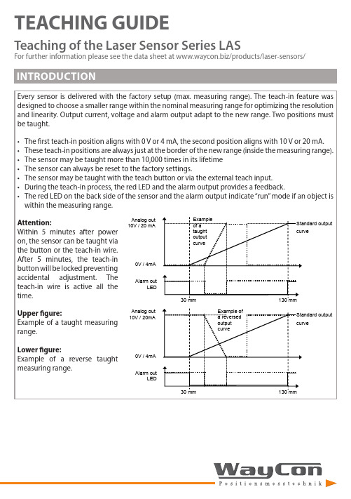
TEACHING GUIDETeaching of the Laser Sensor Series LASFor further information please see the data sheet at /products/laser-sensors/that the distance between sensor and target should be as small as possible. MR stands for the taught measurement S-TM-101618.52123.52605101520MR <4 mm MR 6 mmMR 8 mmMR 10 mm± L i n e a r i t y (μm )Measurement range (mm)1618,52123.526012345678MR <4 mmMR 6 mm MR 8 mm MR 10 mm R e s o l u t i o n (μm )Measurement range (mm)LAS-TM-10416426894120050100150200250300350400MR 2 mm MR 50 mm MR 104 mm± L i n e a r i t y (μm )Measurement range (mm)16426894120020406080100120140160MR 2 mm MR 25 mm MR 50 mm MR 75 mm MR 104 mmR e s o l u t i o n (μm )Measurement range (mm)LAS-TM-3005012520027535000.511.52MR <25 mm MR 150 mmMR 300 mm± L i n e a r i t y (m m )Measurement range (mm)5012520027535000.10.20.30.40.50.6MR <25 mm MR 75 mm MR 150 mm MR 225 mm MR 300 mmR e s o l u t i o n (m m )Measurement range (mm)LAS-TM-5005015025035045055000,511,522,533,54MR 10 mm MR 250 mmMR 500 mm± L i n e a r i t y (m m )Measurement range (mm)5015025035045055000.20.40.60.811.21.4MR 10 mm MR 250 mm MR 500 mmR e s o l u t i o n (m m )Measurement range (mm)that the distance between sensor and target should be as small as possible. MR stands for the taught measurement S-T5-403040506070010203040506070MR 2 mm MR 20 mmMR 40 mm± L i n e a r i t y (μm )Measurement range (mm)30405060700510********MR 2 mm MR 10 mm MR 20 mm MR 30 mm MR 40 mmR e s o l u t i o n (μm )Measurement range (mm)LAS-T5-100305580105130050100150200250MR 3 mm MR 50 mmMR 100 mm± L i n e a r i t y (μm )Measurement range (mm)30558010513001020304050607080MR 3 mm MR 25 mm MR 50 mm MR 75 mm MR 100 mmR e s o l u t i o n (μm )Measurement range (mm)LAS-T5-25050112.5175237.530000.20.40.60.811.2MR 5 mm MR 100 mm MR 250 mm± L i n e a r i t y (m m )Measurement range (mm)50112.5175237.530000.050.10.150.20.250.30.350.40.45MR 5 mm MR 50 mm MR 100 mm MR 175 mm MR 250 mmR e s o l u t i o n (m m )Measurement range (mm)LAS-T5-50010022535047560000.511.522.5MR 10 mm MR 250 mm MR 500 mm± L i n e a r i t y (m m )Measurement range (mm)10022535047560000.10.20.30.40.50.60.70.80.9MR 10 mm MR 100 mm MR 250 mm MR 375 mm MR 500 mmR e s o l u t i o n (m m )Measurement range (mm)LAS-T-800200400600800100000.20.40.60.811.21.41.61.822.2MR 16 mm MR 200 mmMR 400 mm MR 600 mm MR 800 mm ± L i n e a r i t y (m m )Measurement range (mm)200400600800100000.10.20.30.40.50.6MR 16 mm MR 200 mm MR 400 mm MR 600 mm MR 800 mmR e s o l u t i o n (m m )Measurement range (mm)When teaching the measurement range, it is recommended to always select the smallest possible range, because this way the resolution is increased and the linearity error decreased. Also keep in mind that the distance between sensor and target should be as small as possible. MR stands for the taught measurement range.LAS-TB-1050556030323436384042444648± L i n e a r i t y (µm )Measurement range (mm)50556010111213141516R e s o l u t i o n (µm )Measurement range (mm)LAS-TB-4060708090100405060708090100110120130MR 30 mm MR 40 mm± L i n e a r i t y (µm )Measurement range (mm)6070809010010152025303540MR 30 mm MR 40 mmR e s o l u t i o n (μm )Measurement range (mm)LAS-TB-1001001251501752000.10.150.20.250.30.350.40.450.5MR 75 mm MR 100 mm± L i n e a r i t y (m m )Measurement range (mm)1001251501752000.020.040.060.080.100.120.140.16MR 75 mm MR 100 mmR e s o l u t i o n (m m )Measurement range (mm)TEACHING BY TEACH LINELEGEND。
激光位移传感器快速入门指南说明书
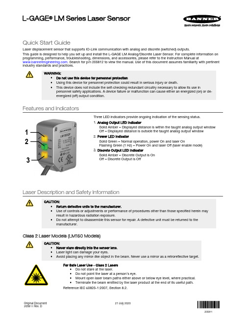
Quick Start GuideLaser displacement sensor that supports IO-Link communication with analog and discrete (switched) outputs.This guide is designed to help you set up and install the L-GAGE LM Analog/Discrete Laser Sensor. For complete information on programming, performance, troubleshooting, dimensions, and accessories, please refer to the Instruction Manual at . Search for p/n 205812 to view the manual. Use of this document assumes familiarity with pertinentindustry standards and practices.WARNING:•Do not use this device for personnel protection•Using this device for personnel protection could result in serious injury or death.•This device does not include the self-checking redundant circuitry necessary to allow its use inpersonnel safety applications. A device failure or malfunction can cause either an energized (on) or de-energized (off) output condition.Features and Indicators132Three LED indicators provide ongoing indication of the sensing status.1. Analog Output LED IndicatorSolid Amber = Displayed distance is within the taught analog output window Off = Displayed distance is outside the taught analog output window 2. Power LED IndicatorSolid Green = Normal operation, power On and laser OnFlashing Green (1 Hz) = Power On and laser Off (laser enable mode)3. Discrete Output LED IndicatorSolid Amber = Discrete Output is On Off = Discrete Output is OffLaser Description and Safety InformationCAUTION:•Return defective units to the manufacturer.•Use of controls or adjustments or performance of procedures other than those specified herein mayresult in hazardous radiation exposure.•Do not attempt to disassemble this sensor for repair. A defective unit must be returned to themanufacturer.Class 2 Laser Models (LM150 Models)CAUTION:•Never stare directly into the sensor lens.•Laser light can damage your eyes.•Avoid placing any mirror-like object in the beam. Never use a mirror as a retroreflective target.For Safe Laser Use - Class 2 Lasers•Do not stare at the laser.•Do not point the laser at a person’s eye.•Mount open laser beam paths either above or below eye level, where practical.•Terminate the beam emitted by the laser product at the end of its useful path.Reference IEC 60825-1:2007, Section 8.2.L-GAGE ® LM Series Laser SensorOriginal Document 205811 Rev. D27 July 2020205811Class 2 LasersClass 2 lasers are lasers that emit visible radiation in the wavelength range from 400 nm to 700 nm, where eye protection is normally afforded by aversion responses, including the blink reflex. This reaction may be expected to provide adequate protection under reasonably foreseeable conditions of operation, including the use of optical instruments for intrabeam viewing.LASER LIGHTDO NOT STARE INTO BEAMCLASS 2 LASER PRODUCTAcc to IEC 60825-1:2007.λ=640-670nm; P=0.45mWPW: 45-1,750msComplies with 21 CFR 1040.10 and 1040.11Except for deviations pursuant to laser noticeNo. 50, Dated June 24, 2007.Figure 1. FDA (CDRH) warning label (Class 2)Class 2 Laser Safety NotesLow-power lasers are, by definition, incapable of causing eye injury within the duration of ablink (aversion response) of 0.25 seconds. They also must emit only visible wavelengths(400 to 700 nm). Therefore, an ocular hazard may exist only if individuals overcome theirnatural aversion to bright light and stare directly into the laser beam.Class 1 Laser Models (LM80 Models)Class 1 lasers are lasers that are safe under reasonably foreseeable conditions ofoperation, including the use of optical instruments for intrabeam viewing.Figure 2. FDA (CDRH) warning label (Class 1) Laser wavelength: 655 nm Output: < 0.33 mW Pulse Duration: 45 µs to 1750 µsInstallation InstructionsSensor InstallationNote: Handle the sensor with care during installation and operation. Sensor windows soiled by fingerprints,dust, water, oil, etc. may create stray light that may degrade the peak performance of the sensor. Blow thewindow clear using filtered, compressed air, then clean as necessary using 70% isopropyl alcohol and cottonswabs or water and a soft cloth.Install the Safety LabelThe safety label must be installed on or near the LM sensors.Note:Position the label on the cable or near the sensor in a location that has minimal chemical exposure.Figure 3. Typical installation; other mounting options are possible.1.Remove the protective cover from the adhesive on the label.2.Wrap the label around the LM cable, as shown.3.Press the two halves of the label together. - Tel: + 1 888 373 6767P/N 205811 Rev. DSensor OrientationCorrect sensor-to-object orientation is important to ensure proper sensing. See the following figures for examples of correct and incorrect sensor-to-object orientation as certain placements may pose problems for sensing distances.Figure 4. Orientation by a wall IncorrectCorrect Figure 5. Orientation in an openingIncorrectCorrectFigure 6. Orientation for a turning objectIncorrectCorrectFigure 7. Orientation for a height difference IncorrectCorrectFigure 8. Orientation for a color or luster difference Figure 9. Orientation for a highly reflective targetApplying tilt to sensor may improve performance on reflective targets. The direction and magnitude of the tilt depends on the application, but a 15° tilt is often sufficient.Mount the Device1.If a bracket is needed, mount the device onto the bracket.2.Mount the device (or the device and the bracket) to the machine or equipment at the desired location. Do not tighten themounting screws at this time.3.Check the device alignment.4.Tighten the mounting screws to secure the device (or the device and the bracket) in the aligned position.Wiring Diagrams+–* Push-Pull output. User-configurable PNP/NPN setting.*Key 1 = Brown 2 = White 3 = Blue 4 = Black 5 = Gray+–* Push-Pull output. User-configurable PNP/NPN setting.*The bare shield wire is connected internally to the sensor housing and should be connected as follows:•If the sensor housing is mounted so that it is in continuity with both the machine frame and earth ground, connect the barewire (also) to earth ground.•If the sensor housing is mounted so that it is insulated from the machine frame and you are experiencing noise, connectingthe bare wire to -V dc (together with the blue wire), may help.•If the sensor is mounted so that it is in continuity with the machine frame, but not with earth ground, do not connect thebare wire (e.g. cut off the bare wire).P/N 205811 Rev. D - Tel: + 1 888 373 67673Configuration InstructionsSensor ProgrammingProgram the sensor using the buttons on the RSD1 remote sensor display accessory, via IO-Link, or the remote input (limited programming options).If you are using the RSD1 for programming, from Run mode, use the buttons to access the Quick Menu and the Sensor Menu. See the instruction manual (p/n 205812) for more information on the options available from each menu. For TEACH options, follow the TEACH instructions in the instruction manual.In addition to programming the sensor, use the remote input to disable the buttons for security, preventing unauthorized or accidental programming changes. See the instruction manual for more information.from Run Mode> 4 sec.Access Sensor Menu Access RSD1 MenuFigure 10. Accessing the MenusRemote Display Buttons and the LMUse the RSD1 buttons Down , Up , Enter , and Escape to view or change RSD1 settings and information and to program a connected sensor.Down and Up Buttons Press Down and Up to:•Access the Quick Menu from Run mode •Navigate the menu systems •Change programming settings•Change individual digit values in distance based settings When navigating the menu systems, the menu items loop.Press Down and Up to change setting values. Press and hold the buttons to cycle through numeric values. After changing a setting value, the value slowly flashes until the change is saved using the Enter button.Enter Button Press Enter to:•Access the Sensor Menu from Run mode •Access the submenus•Move right one digit in distance based settings •Save changesIn the RSD1 Menu, a check mark in the lower right corner of the display indicates that pressing Enter accesses a submenu.Press Enter to save changes. New values flash rapidly, and the sensor returns to the parent menu. - Tel: + 1 888 373 6767P/N 205811 Rev. DEscape ButtonPress and hold Escape for 4 seconds to:•Access the RSD1 Menu while in Run modePress Escape to:•Leave the current menu and return to the parent menuImportant: Pressing Escape discards any unsaved programming changes.In the RSD1 Menu, a return arrow in the upper left corner of the display indicates that pressing Escape returns to the parent menu.Press and hold Escape for 2 seconds to return to Run mode from the RSD1 Menu.Quick MenuThe sensor includes a Quick Menu with easy access to view and change the analog and discrete output switch points.Access the Quick Menu by pressing Down or Up from Run mode. When in the Quick Menu, the current distance measurement displays on the first line and the menu name and the analog value alternate on the second line of the display. Press Enter to access the switch points.Press Down or Up to change the switch point to the desired value.Press Enter to save the new value and return to the Quick Menu.* In Setpoint mode, SPt1 Pt is replaced by SPt and SPt2 Pt is not available.In Dual mode, SPt1 is replaced by DualSPt and SPt2 Pt is not available.Sensor Menu (MENU)Access the Sensor Menu by pressing Enter from Run mode. The Sensor Menu is also accessible from the Quick Menu: navigate to MENU and press Enter. The Sensor Menu includes several submenus that provide access to view and change sensor settings and to view sensor information.P/N 205811 Rev. D - Tel: + 1 888 373 67675SensorMenu Full MapFrom Run mode, press Enter to enter the top-level menu system (A_OUT, D_OUT, INPUT, MEASURE, etc).Top Menu* Factory default setting - Tel: + 1 888 373 6767P/N 205811 Rev. DSpecificationsSupply Voltage (Vcc)10 V dc to 30 V dcUse only with a suitable Class 2 power supply (North America) Power and Current Consumption, exclusive of loadNormal Run Mode: 1.5 W, Current consumption < 62 mA at 24 V dc Supply Protection CircuitryProtected against reverse polarity and transient overvoltages Ambient Light Immunity10,000 luxConstructionHousing: stainless steelWindow: acrylic Sensing BeamVisible red, 655 nmSensing RangeLM80: 40 to 80 mmLM150: 50 mm to 150 mmDelay at Power Up2.1 sMeasurement/Output Rate0.25 ms to 4 ms; user selectable from the Speed menu Output ConfigurationAnalog output: 4 to 20 mA (LM...I Models) or 0 to 10 V DC (LM...U Models)Discrete output: Push/Pull, IO-LinkOutput RatingsDiscrete Output: 50 mA maximum (protected against continuous overload and short circuit)Output saturation voltage (PNP): < 3 V at 50 mAOutput saturation voltage (NPN): < 2.5 V at 50 mAAnalog current output (LM...I Models): 500 Ω maximumAnalog voltage output (LM...U Models): 1000 Ω minimum Maximum Torque1.5 N·mRemote InputAllowable Input Voltage Range: 0 to VccActive Low (internal weak pullup—sinking current):High State: > 3.6 VLow State: < 2.4 VActive High (internal weak pulldown—sourcing current): High State: > Vcc - 2.9 VLow State: < Vcc - 4.6 VMinimum Window Size, Analog and DiscreteLM80:Analog: 1 mmDiscrete: 0.024 mmLM150:Analog: 1 mmDiscrete: 0.1 mm Analog ResolutionLM80: 0.002 mmLM150: 0.004 mmRepeatabilityLM80: ± 0.001 mm1LM150: ± 0.002 mm 2Analog and IO-Link LinearityLM80:40–70 mm: ± 0.02 mm70–80 mm: ± 0.03 mmLM150:50–120 mm: ± 0.06 mm120–150 mm: ± 0.07 mmIO-Link Accuracy3LM80: ± 0.175 mmLM150: ± 0.2 mmTemperature Effect, TypicalLM80: ± 0.006 mm/°CLM150: ± 0.008 mm/°CResponse TimeTotal response speed varies from 0.5 ms to 2048 ms, depending on base measurement rate and averaging settings.See Instruction Manual for more information.Minimum Object SeparationLM80:Uniform targets (6% to 90% reflectivity) 40–70 mm: 0.04 mmUniform targets (6% to 90% reflectivity) 70–80 mm: 0.06 mmNon-uniform targets (6% to 90% reflectivity): 0.4 mmLM150:Uniform targets (6% to 90% reflectivity) 50–120 mm: 0.120 mmUniform targets (6% to 90% reflectivity) 120–150 mm: 0.140 mm Non-uniform targets (6% to 90% reflectivity): 0.8 mm Environmental RatingIEC IP67Operating Conditions–10 °C to +55 °C (+14 °F to +131 °F)90% at +55 °C maximum relative humidity (non-condensing) Storage Temperature–35 °C to 60 °C (–31°F to 140 °F)Boresighting± 0.70 mm at 40 mm± 0.87 mm at 50 mm± 1.40 mm at 80 mm± 2.62 mm at 150 mmVibration/Mechanical ShockMeets IEC 60947-5-2 (10 to 60 Hz max., double amplitude 0.06 in, max acceleration 10G. 30G 11 ms duration, half sine wave) Application NoteFor optimum performance, allow 10 minutes for the sensor to warm upCertificationsUL Type 1with 128× averaging. With 1× averaging, repeatability of ± 0.004 mm from 40 to 80 mm.with 128× averaging. With 1× averaging, repeatability of ± 0.005 mm from 50 to 120 mm and ± 0.010 mm from 120 to 150 mm.3The accuracy specification refers to the possible absolute offset when installing a sensor without taking any reference measurement.Linearity is the more relevant specification for most applications.P/N 205811 Rev. D - Tel: + 1 888 373 67677Typical Beam Spot Size4Required Overcurrent ProtectionWARNING: Electrical connections mustbe made by qualified personnel inaccordance with local and nationalelectrical codes and regulations.Overcurrent protection is required to be provided by endproduct application per the supplied table.Overcurrent protection may be provided with external fusing orvia Current Limiting, Class 2 Power Supply.Supply wiring leads < 24 AWG shall not be spliced.For additional product support, go to.FCC Part 15 and CAN ICES-3 (B)/NMB-3(B)This device complies with part 15 of the FCC Rules and CAN ICES-3 (B)/NMB-3(B). Operation is subject to the following two conditions:1.This device may not cause harmful interference, and2.This device must accept any interference received, including interference that may cause undesired operation.This equipment has been tested and found to comply with the limits for a Class B digital device, pursuant to part 15 of the FCC Rules and CAN ICES-3 (B)/NMB-3(B). These limits are designed to provide reasonable protection against harmful interference in a residential installation. This equipment generates, uses and can radiate radio frequency energy and, if not installed and used in accordance with the instructions, may cause harmful interference to radio communications. However, there is no guarantee that interference will not occur in a particular installation. If this equipment does cause harmful interference to radio or television reception, which can be determined by turning the equipment off and on, the user is encouraged to try to correct the interference by one or more of the following measures:•Reorient or relocate the receiving antenna.•Increase the separation between the equipment and receiver.•Connect the equipment into an outlet on a circuit different from that to which the receiver is connected.•Consult the manufacturer.Banner Engineering Corp. Limited WarrantyBanner Engineering Corp. warrants its products to be free from defects in material and workmanship for one year following the date of shipment. Banner Engineering Corp. will repair or replace, free of charge, any product of its manufacture which, at the time it is returned to the factory, is found to have been defective during the warranty period. This warranty does not cover damage or liability for misuse, abuse, or the improper application or installation of the Banner product.THIS LIMITED WARRANTY IS EXCLUSIVE AND IN LIEU OF ALL OTHER WARRANTIES WHETHER EXPRESS OR IMPLIED (INCLUDING, WITHOUT LIMITATION, ANY WARRANTY OF MERCHANTABILITY OR FITNESS FOR A PARTICULAR PURPOSE), AND WHETHER ARISING UNDER COURSE OF PERFORMANCE, COURSE OF DEALING OR TRADE USAGE. This Warranty is exclusive and limited to repair or, at the discretion of Banner Engineering Corp., replacement. IN NO EVENT SHALL BANNER ENGINEERING CORP. BE LIABLE TO BUYER OR ANY OTHER PERSON OR ENTITY FOR ANY EXTRA COSTS, EXPENSES, LOSSES, LOSS OF PROFITS, OR ANY INCIDENTAL, CONSEQUENTIAL OR SPECIAL DAMAGES RESULTING FROM ANY PRODUCT DEFECT OR FROM THE USE OR INABILITY TO USE THE PRODUCT, WHETHER ARISING IN CONTRACT OR WARRANTY, STATUTE, TORT, STRICT LIABILITY, NEGLIGENCE, OR OTHERWISE.Banner Engineering Corp. reserves the right to change, modify or improve the design of the product without assuming any obligations or liabilities relating to any product previously manufactured by Banner Engineering Corp. Any misuse, abuse, or improper application or installation of this product or use of the product for personal protection applications when the product is identified as not intended for such purposes will void the product warranty. Any modifications to this product without prior express approval by Banner Engineering Corp will void the product warranties. All specifications published in this document are subject to change; Banner reserves the right to modify product specifications or update documentation at any time. Specifications and product information in English supersede that which is provided in any other language. For the most recent version of any documentation, refer to: .For patent information, see /patents.© Banner Engineering Corp. All rights reserved。
激光传感器使用说明书
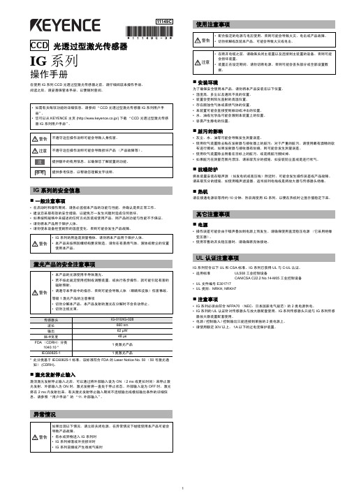
光透过型激光传感器IG 系列操作手册在使用 IG 系列 CCD 光透过型激光传感器之前,请仔细阅读本操作手册。
阅读之后,请妥善保管本手册,以便随时查阅。
IG系列的安全信息⏹一般注意事项•在启动时和操作期间,请务必监视本产品的功能与性能,并确认是否正常工作。
•建议您采取有效的安全措施,以避免万一发生问题时造成任何损坏。
•如果按照规格中未描述的任何方式改装或使用产品,则产品的功能与性能不予保证。
•请勿将本产品用于保护人体。
•请勿使本设备经受剧烈的温度变化,否则可能会发生产品故障。
*此分类基于 IEC60825-1 标准,该标准符合 FDA 的 Laser Notice No. 50(50 号激光通知)(CDRH)。
⏹激光发射停止输入激活激光发射停止输入之后,可以通过将外部输入设为 ON(2 ms 或更长时间)来停止激光发射。
外部输入为 ON 时,激光发射将一直处于停止状态。
外部输入设为 OFF 时,激光将在 2 ms 内发射出来。
有关激光发射停止输入期间不连续输出或模拟输出条件的详细信息,请参照“用户手册”的“11. 外部输入”。
异常情况使用注意事项⏹安装环境为了确保安全使用本产品,请勿将本产品安装在以下位置。
•湿度高、多尘以及通风不良的位置。
•装置会受到阳光直射的高温位置。
•存在腐蚀性气体或易燃气体的位置。
•本装置可能会直接受到振动或冲击的位置。
•水、油或化学品可能会溅到本装置上的位置。
•容易产生静电的位置。
⏹脏污的影响•灰尘、水、油等可能会导致发生测量误差。
•使用吹气装置除去粘在发射器与接收器上的脏污;对于严重的脏污,请使用蘸有酒精的软布进行擦拭。
如果发射器与接收器有划痕,则可能会发生测量误差。
•使用吹气装置除去附着在目标上的脏污,或是将脏污擦拭掉。
•如果脏污在测量范围内漂浮,请采取充分的措施,如安装防尘盖或是进行吹气。
⏹抗噪防护将本装置安装在噪声源(如发电机或高压线)附近时,可能会发生操作误差或产品故障。
激光测距传感使用手册

激光测距传感使用手册前言尊敬的客户:衷心的感谢您选择了深圳市南方测控技术有限公司的激光测距传感器!为了让您更好的使用本激光测距传感器与防止意外事故的发生,请您在使用本激光测距传感器前仔细的阅读本说明书。
本说明书的版权归属深圳市南方测控技术有限公司所有,如在不影响本激光测距传感器整体性能的前提下所作的修改或更新,恕不另行通知。
激光测距传感器系统说明术语解释➢激光测距:利用激光对目标的距离进行准确测定。
激光测距一般采用两种方式来测量距离:脉冲法和相位法。
➢脉冲激光测距:基于激光脉冲反射时差法原理,测距仪器发射出的激光经被测量目标反射后,激光束被测距仪器接收,测距仪器记录激光往返的时间。
光速和往返时间的乘积的一半,就是测距仪器和被测量物体之间的距离。
➢激光测距传感器:为工业测量之产品,采用工业标准设计、生产和检测,可在线24小时连续实施测量,有的可以多台组网测试。
➢激光安全等级:国际上对激光有统一的分类,激光器分为四类(Class1、Class2、Class3、Class4)。
Class1激光器对人是安全的,Class2激光器对人有较轻的伤害,Class3以上的激光器对人有严重伤害,使用时需特别注意,避免对人眼直射。
➢Class2激光器:指激光器的出口光功率小于1mw,一般认为对人的眼睛是安全的,正常暴露在这种激光器的光束下不会对眼睛的视网膜造成永久性的伤害。
尽管此种激光器是安全的,但也不能长时间的直视激光光束。
如偶尔照射到人眼还不至于引起伤害,但连续观察激光束时能损伤眼睛。
此是对第二级激光器的最重要控制措施。
➢系统概述LPS系列激光测距传感器是一种功能强大的测量精确、无接触式的工业用距离测量设备,它可广泛地被集成用于各种工业用途的控制和监测系统上。
使用图例如下:LPS系列激光测距传感器是一款使用方便的工业应用激光测距仪表,特别为交通、炼钢、仓储、建筑、码头等需要自动进行距离和位置控制的应用而设计研发,具有很高地实用性。
激光位移传感器操作手册说明书

激光位移传感器操作手册V2.0目录第1章:产品概要......................................................................... 1-11.1 包装内容 ......................................................................................... 1-11.2 各部件名称及功能........................................................................... 1-21.3 安装................................................................................................. 1-3 第2章:设定与测量 ..................................................................... 2-1 第3章:软件操作......................................................................... 3-13.1 通信设置 ......................................................................................... 3-13.2 位置读取与归零设定 ....................................................................... 3-2 第4章:通讯指令......................................................................... 4-14.1 通讯参数列表 .................................................................................. 4-14.2 通讯协议 ......................................................................................... 4-4 第5章:产品规格......................................................................... 5-1 第6章:安全注意事项.................................................................. 6-1 第7章:保固 ................................................................................ 7-1版本更新历程激光位移计操作手册V2.0版本更新历程版本更新日期V1.0 第一版发行2018/09/03V2.0 新增「反应速度设定」与「中值滤波器设定」功能说明与通讯地址设定方式。
- 1、下载文档前请自行甄别文档内容的完整性,平台不提供额外的编辑、内容补充、找答案等附加服务。
- 2、"仅部分预览"的文档,不可在线预览部分如存在完整性等问题,可反馈申请退款(可完整预览的文档不适用该条件!)。
- 3、如文档侵犯您的权益,请联系客服反馈,我们会尽快为您处理(人工客服工作时间:9:00-18:30)。
RLM-S30 激光测距传感器 用户手册
上海誉煊电子技术有限公司
电话:021-68413203 传真:021-51862869 邮箱:sales@ 地址:上海市浦东新区上南路 2779 号 209 室
上海誉煊电子技术有限公司 上海市浦东新区上南路 2779 号 209 室 TEL:021-68413203
上海誉煊电子技术有限公司 上海市浦东新区上南路 2779 号 209 室 TEL:021-68413203
RLM-S30 激光测距传感器 用户手册
订货说明
一套设备构成:
主机 线缆
资料光盘 合格证
出货清单
包装盒
1台 1条
1个
1份
1张
1个
注:如需开具发票,请购货前通知销售人员;发票有可能随货寄出,也有可能后面补寄,具体以销售人员通知 为准。
随着公司的不断努力和发展,誉煊电子将陆续推出一系列具有积极意义的全新高科技产品。
1.3 产品特性
★ 精度 ±1.5mm
★ 频率最高 10Hz ★ 距离最远 30m ★ RS232 /RS485/CANBUS/4-20mA/TTL/MODBUS
★1任.4 主选要其一应用
钢铁厂和轧钢厂用于过程监控
料位、液位的测量
针脚 1 2 3 4 5
定义 电源+ 电源地 信号+ 信号GND
线缆颜色 红色 黑色 蓝色 黄色 绿色
航空插头型号:GX16
上海誉煊电子技术有限公司 上海市浦东新区上南路 2779 号 209 室 TEL:021-68413203
安装尺寸
RLM-S30 激光测距传感器 用户手册
行车定位系统、装卸处理设备的定位系统 起重安装设备位置控制 车辆、船舶的定位监控系统
距离、位置、液位、料位、生产线料坯传ቤተ መጻሕፍቲ ባይዱ定 位
★ 响应时间≤0.1s ★ 宽压 DC +15-24V ★ 体积小 110*92*37mm ★ IP67 防水
大型货架库存管理 超大物体几何计量 靶距自动控制 电气化铁路接触网测量 铁路建筑物限界测量以及江河湖海等的水位 测量行吊 XY 定位 电梯运行测量 大型工件装配定位
上海誉煊电子技术有限公司 上海市浦东新区上南路 2779 号 209 室 TEL:021-68413203
RLM-S30 激光测距传感器 用户手册
内置 DSP 高速数字信号处理器、外部设置简洁醒目的工作状态指示 LED、开关量输出状态指示、总线接口等,
集高速、安全、智能、数字化、承载电流大等诸多优点于一体,能有效保障低压直流场合的电气安全。
仪器尺寸
110*92*37mm
外壳材料
铝合金磨砂氧化
重量
450g
保护电路 机械参数 防护等级
有 IP67
防震等级
EN 60947-5-2
工作温度
-20℃......+70℃
存储温度
-40°......+85℃
接口
GX16 六芯
☞ 注释:
1、 信号输出频率最高为 10HZ, 可通过附带软件修订
2、 精度随距离增大而变大,随频 率增大而变大。
RCP-A 型智能直流短路保护器是我公司针对汽车电气短路保护研制之产 品,该产品针对 36V 以下低压直流场合设计,产品使用时串联于蓄电池和负载 回路中,当负载发生短路故障时,装置在几十微秒内(相比传统保险丝或者其它 短路保护装置,切断故障电流的速度提高近万倍)瞬间切断短路异常电流,能有 效避免因蓄电池电气短路而引发的汽车自燃等恶性安全事故,当短路故障排除后 按下本装置上的复位按钮,电气回路重新接通,装置恢复至正常工作模式;产品
3、RLM-S60 为客户提供了多种 输出信号,客户订购前请务必 确认好所需信号,产品只能选 择其中一种,不可同时输出。
上海誉煊电子技术有限公司 上海市浦东新区上南路 2779 号 209 室 TEL:021-68413203
接口说明
RLM-S30 激光测距传感器 用户手册
货品型号:(购货前务必确认好所选输出信号对应的产品型号)
注意事项
1、测距传感器是以激光为介质进行测量,由于激光受光线和被测物的影响,故传感器也受到光线和被测物的 影响:一般强光会导致距离变短,黑暗环境下效果最好;被测物黑色或橡胶材质会缩短距离,白色等浅色物质效果 最好;空气中有粉尘会导致距离变短。
2、传感器的精度与频率和距离有关系:一般距离越远,频率越高精度越差;距离越近,频率越低精度越好。 3、传感器的激光类型为不可见光,安装调试时可以打开手机摄像头可看到光斑或带上滤光眼镜。
RLM-S 系列激光测距传感器是上海誉煊电子技术有限公司研发的新一代测距 传感装置,产品集功能强大、性能稳定可靠、安装使用方便、应用范围广等诸多优 点于一体,是一种性能优良的经济型实时距离监测产品。RLM-S 系列激光测距传感 器具有优越的测试精度和极高的稳定性,实现了高精度、无接触、不间断的距离及形变监控,在隧道形变、桥 梁位移、建筑测量、仓储物流、工业现场及过程、交通港口等场合有着非常广阔的应用。
RLM-S30 激光测距传感器 用户手册
RLM-S30 激光测距传感器 用户手册
Revision 16.1.28
上海誉煊电子技术有限公司 上海市浦东新区上南路 2779 号 209 室 TEL:021-68413203
RLM-S30 激光测距传感器 用户手册
产品概述
1.1 关于产品
RLM-S30 激光测距传感器是上海誉煊电子技术有限公司研发的新一代测距传感装置,产品集功能强大、 性能稳定可靠、安装使用方便、应用范围广等诸多优点于一体,是一种性能优良的经济型实时距离监测产品。 RLM-S30 激光测距传感器具有优越的测试精度和极高的稳定性,实现了高精度、无接触、不间断的距离及形 变监控,在隧道形变、桥梁位移、建筑测量、仓储物流、工业现场及过程、交通港口等场合有着非常广阔的应 用。
售后服务
1、产品质保期为 12 个月。质保期内,由于操作不当等人为因素造成的质量问题不在质保范围内;
2、如有使用方面的问题,请电询我司。 3、保修期内维修时,发货时请注明仪器问题及发货单位,购买时间等。快递费单向支付,到付运费恕不接收。
上海誉煊电子技术有限公司 上海市浦东新区上南路 2779 号 209 室 TEL:021-68413203
10Hz 可调
激光
可见激光
激光等级 光学参数 激光波长
II 类安全激光 905nm
光斑大小
10mm@10m
激光寿命
>50000h
输入电压
DC +9-36V
激光功率
<10mW
电气参数 标准协议
MODBUS-485
数字量输出 TTL/RS232/485/CAN BUS
模拟量输出
4-20mA
最大负载
250Ω
运动物体位置监控
上海誉煊电子技术有限公司 上海市浦东新区上南路 2779 号 209 室 TEL:021-68413203
RLM-S30 激光测距传感器 用户手册
技术参数
型号 RLM-S30
参数
量程
0.1-30m
性能参数
精度 分辨率
精度±1.5mm 1mm
输出频率
RLM-S30 采用相位法测距的原理,能够达到高精度、中远距离的监测。
1.2 关于公司
上海誉煊电子技术有限公司成立于 2013 年,是一家集研发、生产、销售于一 体的高新技术企业。公司产品主要向多元化方向发展,本着人文为本、科技创新的精 神、在不同的领域内研发了一系列完全具有自主知识产权的高新技术产品,其中某些 产品在性能价格上具有独特的优势,填补了市场空白。