938D焊台调试说明
恒温焊台操作指导书

3.设定温度到达后,恒温灯灭(数显式读数处于稳定状态),可以开始焊锡工作。
4.烙铁在不用时必须摆放在烙铁座上。
5.烙铁咀及金属部件有高温,严禁用手触摸,以免烫伤。
6.工作完毕,将烙铁咀用湿海棉擦干净后加上锡摆回烙座,关闭电源。
7.当焊台有故障时,必须关闭电源,通知技术员维修。
4.调校方式:将焊台“CAL”上的胶塞取下,用螺丝批调节微调电位器(顺转是升温,逆转是降温)。
调节微调电位器必须要轻力,当调节没有变化时要将焊台交技术员维修。此项由专人负责,非授权
人员不可以调校;
5.检测时焊台必须在处在恒温状态进行。
四、烙铁咀落地阻值检测
1.把焊台的三脚电源线插入电插座,并将开关开启.
一、保养指示
1.保持焊台外表洁净,工作完毕由使用者擦抹一次。
2.保持烙铁咀干净,不用时用湿海棉擦干净并加上锡层防止烙铁咀氧化。
3.严禁用利器剔除烙铁咀上的氧化物,必须用湿海棉抹擦。
二、温度检测
1.焊台烙铁咀的温度必须符合工位WI要求。
2.开拉前及每四小时,需检测烙铁温度一次并作检测记录。
3.检测时如使用温度与设定温度不相符时,必需停止使用烙铁,校对准确后才可以使用。
B.用沙纸将烙铁咀与烙铁蕊接触位的氧化物打磨干净及清除烙铁蕊外表的污积。
C.清理干净后将烙铁咀装好,重新检测。
五、检测记录由检测部保存12个月。
2.将数字表的量程打到电阻档,一表笔接烙铁咀,另一表笔接拉落地线,数字表显示读数是烙铁咀落地
阻值。烙铁咀落地阻值每每四小时由使用部门检测一次。
3.标准要求烙铁咀落地阻值<100Ω,当检测值>100Ω时必须修理工后才使用。检修方式:
夯实智能936焊台

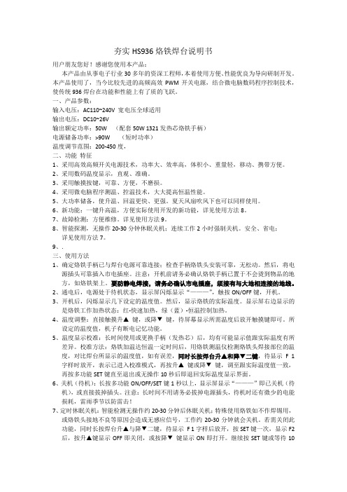
夯实HS936烙铁焊台说明书用户朋友您好!感谢您使用本产品:本产品由从事电子行业30多年的资深工程师,本着使用方便、性能优良为导向研制开发。
本产品使用了,当今比较先进的高频高效PWM开关电源,结合微电脑数码程序控制技术,使传统936焊台在功能和性能上有了质的飞跃。
一、产品参数:输入电压:AC110~240V 宽电压全球适用输出电压:DC10~26V输出额定功率:50W (配套50W 1321发热芯烙铁手柄)电源储备功率:>90W (短时功率)温度调节范围:200-450度,二、功能特征1、采用高效高频开关电源技术,功率大、效率高,体积小、重量轻,移动、携带方便。
2、采用数码温度显示,直观、准确。
3、采用触摸按键,可靠、方便,不磨损。
4、采用微电脑程序测温、控温技术,大大提高恒温性能。
5、大功率储备,使升温、回温更快、更强。
夏天风扇吹风下也可以同样使用。
6、新功能:一键升高温,方便实际使用开发的新功能,详见使用方法8。
7、故障检测:方便维修。
详见使用方法9。
8、智能探测,无操作20-30分钟休眠关机;连续工作2小时强制关机。
安全、省电;详见使用方法7。
9、.三、使用方法1、确定烙铁手柄已与焊台电源可靠连接;检查手柄烙铁头安装可靠,无松动。
然后,将电源插头可靠插入市电插座。
注意:开机前请务必确认烙铁手柄已置于不会烫到物品的地方,如烙铁架上。
要防静电焊接,请务必确认市电插座,须接有与大地相连接的地线。
2、通电后,电源处于待机状态,显示屏闪烁显示“———”,触按ON/OFF键,开机。
3、开机后,闪烁显示几下设定的温度值。
然后,显示烙铁的实际温度。
显示屏右边显示的是烙铁工作加热状态:红-快速加热,绿(蓝)-恒温控制加热。
4、温度调整:直接触摸升▲键,或降▼键,待屏幕显示所需温度后放开触摸键即可。
所设定的温度值,机子有断电记忆功能。
5、温度显示校准:长时间使用或更换手柄(发热芯)后,均有可能显示值跟实际温度有所差异。
快克205焊台使用说明书

Lead Free Soldering Station 大型智能无铅电焊台高周波发热极速回温操作手册感谢您购买我们的无铅电焊台,本产品是专为无铅焊接而设计的,使用前请仔细阅读本说明书,阅读后请妥为保管,以便日后查阅。
目录注意事项……………………………………………………………………… 部件名称……………………………………………………………………… 装置和使用电焊台…………………………………………………………… 参数…………………………………………………………………………… 休眠……………………………………………………………………………选择合适的烙铁头来适应焊接要求………………………………………… 校准烙铁温度………………………………………………………………… 烙铁头的使用………………………………………………………………… 烙铁头的保养………………………………………………………………… 错误标记……………………………………………………………………… 排除故障指南………………………………………………………………… 如何检查发热器及传感器元件……………………………………………… 更换保险丝…………………………………………………………………… 规格…………………………………………………………………………… 烙铁头…………………………………………………………………………注意事项△!警告本使用说明书之“警告”和“注意”的定义如下:△!警告:滥用可能导致使用者死亡或重伤△!注意:滥用可能导致使用者受伤或对涉及物体造成实质破坏。
△!注意当电源接通时,烙铁头温度处于高温状态。
鉴于滥用可能导致灼伤或火患,请严格遵守以下事项:● 请避免本焊台的滥用,应按照操作说明使用本品。
● 切勿触及烙铁头附近的金属部份。
● 切勿在易燃物体附近使用烙铁头。
● 通知工场其他人士,烙铁头极易灼伤,可能引起危险事故。
休息时或完工后应关掉电源。
电焊台使用说明书

电焊台使用说明书AT8586多功能一体化集成拆焊维修系统型号:AT8586 品牌:安泰信(ATTEN) 应用范围1.工业生产进行电子产品装配2.科研部门进行产品开发3.维修行业进行电子产品检修4.各企事业单位电工进行锡焊操作5.电子技术爱好者进行电子装配6.各类院校电类学生进行技能实训功能特点●传感器闭合回路,微电脑PID控制,控温精确。
LED数码显示各种状态,按键切换,方便直观。
●热风枪功率大,升温迅速,出风柔和,风量大,非常适合无铅拆焊作业。
●焊台发热体采用低压电源供电,能有效的保护敏感器件及工作人员安全。
●完美的二合一组合,采用塑料外壳,机身小巧,占用工作台面积小。
●故障自我检测报警功能。
技术参数总机额定电压:AC 220V±10% 50Hz整机功率:750W±10%(最大)工作环境:0~40℃相对湿度<80%储存温度:-20~80℃相对湿度<80%热风枪部分工作电压:AC 220V±10% 50Hz输出功率:700W±10%温度范围:100℃~500℃气流量120L/min(最大)温度稳定度:±2℃(静态)设置方式:按键调节显示方式:LED数显校温方式:数字校准温度锁定方式:数字式喷咀:A1130、A1170、A1110发热丝:700W 220V AT858发热丝电焊台部分工作电压:AC 26V±10% 50Hz输出功率:50W±10%温度范围:200℃~480℃温度稳定度:±2℃(静态)设置方式:按键调节显示方式:LED数显校温方式:数字校准温度锁定方式:数字式焊咀对地阻抗:<2Ω焊咀对地电压:<2mV烙铁头:AT-02-SI发热芯:50W四芯陶瓷发热芯包装清单(购买时请检查包装,以证实所列清单项目正确无误。
)●设备主机连热风枪手柄:1台●热风枪手柄支架:1套●电焊铁:1支●烙铁座:1个●电源线:1条●清洁海绵:1份●说明书:1本●保修卡:1份使用指南1.安装新机器第一次使用时,必须安装热风枪手柄支架,如下图。
焊台、热风枪的基础知识(高级电子技术人员需要掌握的技能)

焊台、热风枪的基础知识(高级电子技术人员需要掌握的技能)对于有一定基础的实际操作人员、电子爱好者来说。
光会使用电烙铁远远达不到他们的要求。
对于作业需要,对于兴趣需要和能力的提升,我们需要新的装备,那就是焊台,热风枪。
下面我就讲一下焊台和热风枪的使用方法和注意事项。
先说注意事项。
1、电焊台烙铁头应尽量靠近元器件引脚。
但是不能用力碰元器件引脚。
不然引脚容易损坏。
2、切忌不可在焊接时用力顶压烙铁头,以免使烙铁头变形,严重时可能会?报废。
3、在焊接大面积接地或使用无铅焊锡的元器件时,可将温度调到400~450度左右,且可以加热时间略长一些。
在焊接完这类元器件后,必须将温度再调到300~400度左右。
4、当发现烙铁头上粘有黑色污垢时,应马上去除污垢,防止烙铁头氧化(俗称的死头)。
这一点,可以使用高温海绵,把高温海绵放在烙铁架槽里,加水,使海绵膨胀开来。
烙铁头上粘有黑色污垢时,在海绵上擦几下,要擦掉。
防止氧化。
5、一旦死头,可以在焊锡多的地方多磨几次烙铁头,这样可以减少死头的面积,慢慢地死头现象就会消失。
一旦氧化,就粘不上锡了。
烙铁头就会慢慢没有用。
这时候就需要烙铁头修复剂了。
6、当温度调节不准确时,可以通过微调主旋钮下方小孔的可调电阻校准。
使用方法:这里通过焊接贴片电阻,芯片的例子来说明。
1.在焊接之前先在焊盘上涂上助焊剂,用烙铁处理一遍,以免焊盘镀锡不良或被氧化,造成不好焊,芯片则一般不需处理.2.用镊子小心地将芯片放到PCB板上,注意不要损坏引脚.使其与焊盘对齐,要保证芯片的放置方向正确.把烙铁的温度调到300多摄氏度,将烙铁头尖沾上少量的焊锡,用工具向下按住已对准位置的芯片,在两个对角位置的引脚上加少量的焊剂,仍然向下按住芯片,焊接两个对角位置上的引脚,使芯片固定而不能移动.在焊完对角后重新检查芯片的位置是否对准.如有必要可进行调整或拆除并重新在PCB板上对准位置.3.开始焊接所有的引脚时,应在烙铁尖上加上焊锡,将所有的引脚涂上焊剂使引脚保持湿润.用烙铁尖接触芯片每个引脚的末端,直到看见焊锡流入引脚.在焊接时要保持烙铁尖与被焊引脚并行,防止因焊锡过量发生搭接.4.焊完所有的引脚后,用焊剂浸湿所有引脚以便清洗焊锡.在需要的地方吸掉多余的焊锡,以消除任何短路和搭接.最后用镊子检查是否有虚焊,检查完成后,从电路板上清除焊剂,将硬毛刷浸上酒精沿引脚方向仔细擦拭,直到焊剂消失为止. 其实实践中,焊接芯片,主要是用热风枪来完成,因为热风枪没有接触,防静电性能比较好。
938D焊台调试说明

使用方法
1.连接
•将手柄插头插入主机前面板并旋紧,然后置于烙铁座上。
•将电源线插头插入电源插座。
2.上电
打开电源开关,显示设定温度(上一次的使用温度值)3秒,之后显示实际温度值,符号位显“C或。
F”。
(图1)、(图2)
3.温度调整
正常工作时,长按“▲”键或“ ▼ ”键进入温度调整状态,进入温度调整状态之后长按可快速调整设置温度;短按步进调整设置温度,同时显示闪烁。
停止按键3秒温度自动保存。
4.快捷温度
正常工作时,通过可编程快捷按键可以快速设置工作温度,短
按“1、2、3 ”键即可提取存储于该快捷通道的设置温度置于当前工作温度。
再按住“ #”键的同时按住“ 1、2、3”键可将当前设置的工作温度值分别存储于快捷通道“ 1、2、3”。
5.温度校正
当更换发热芯或烙铁头,需校正焊咀温度时,长按(>3秒)“”键进入温度校正模式,闪烁显示校正温度值,按“▲”键或“▼”键可直接调整校正值,校正值是实际测量的温度值减去设置温度的差值(例:实际值380 C -设置值350 C 〜+30C,按“▲”键上调30度;实际值320 C -设置值350 C 〜-30C,按“▼”键下调30度)。
温度校正范围+50C〜-50 C, 输入完成按“※”键确认保存。
6.温度单位转换在关机状态下按住“#”键再打开电源开关,温度单位自动在“C”和“。
F”之间转换并自动保存
7.故障报警当显示屏出现“ H - E”或“ S - E符号,表明发热体或其相关部分电路出现故障。
(注:范文素材和资料部分来自网络,供参考。
只是收取少量整理收集费用,请预览后才下载,期待你的好评与关注)。
AT938D AT980D 电子焊接站 thermal-control 反静电用户手册说明书

TMIn this instruction manual, “Warning” and “Caution” are defined as follows.!WARNINGS:T emperature of iron tip will be up to 150 - 450°C after connecting power, so it may lead to injury or fire because of improper usage. Please abide the following terms:Don’t touch the iron tip or surrounding metals.Never operate it near the flammable gas or substance.Disconnect from power source if the unit will not be used for long periods. Switch off power during short breaks.Replace accessories or iron tip after turning off the station and let it cool down.Never operate this device,ifyou don’t have soldering experience or enough knowledge to use.Keep away from childrenSafety Precautions:C aution : Improper usage can cause serious injury to personnel and/or damage to equipment. For personnel safety, please follow these precautionsNever use it to do other work except soldering.Do not subject the main unit to physical shock. Never drop or sharply jolt the unit.Don’t change the device at willReplace loss items with original accessories of ATTEN.Don’t put it in water or operate with wet handsDon’t pull the cable but hold tightly the plug when you take it out of plug.Please keep the operate place well ventilated since soldering process produce smoke.Don’t play with other people or would be easy to hurt others or yourself.T his appliance can be used by children aged from 8 years and above and persons with reduced physical, sensory or mental capabilities or lack of experience and knowledge if they have been given supervision or instruction concerning use of the appliance in a safe way and understand the hazards involved. Children shall not play with the appliance. Cleaning and user maintenance shall not be made by children without supervision.I f the supply cord is damaged, it must be replaced by the manufacturer,its service agent or similarly qualified persons inorder to avoid a hazard.WARNING: This tool must be placed on its stand when not in use.What’s IncludedDevice 1PCSoldering Iron 1SETIron Holder 1PCPower Cord 1PCManual 1 CopyClean Sponge 1PC TMSpecifications:ModelAT938DAT980DPower ConsumptionAC (100V/110V/120V||220V/230V/240V)50/60Hz (optional)Temperature Controlling Range 150°C to 450°C (302°F to 842°F)Output Voltage 26V AC Temperature Stability ±2°C (static)DisplayLCD Max. Surrounding Temperature 40°C Calibrating MethodDigital Calibration Temperature Range for Calibration 50°C to -50°C (90°F to -90°F)Ground Impedance <2ΩGround Voltage <2mVLocked Temperature -Locking state on display Heating Element2 Cores (ATTEN)High end quad-wire heater*Specifications are subject to change without prior notice.Heating element (pic) TMAT938D/AT980D Control Panel Guide:Introduction for LCD display:Features:• New appearance design, big LCD screen, for clear and convenient reading.• PID power control loop with constant temperature set by MCU computer for more precision temperature control.• Imported temperature-beard materials with long life.• It is convenient that the device adopt three programmable knobs in different condition.• Display the temperature between Fahrenheit and Celsius flexibly, convenient for the type of operators.• Computerized temperature calibration can correct the difference between the actual and display temperature quickly.• Heating clement malfunction alert.Operating GuidelinesPlease refer to the “Control Panel Guide” section for buttons and display panel details1. Connection:1.1. Insert soldering iron’s plug into the socket and tighten the nut on the plug securely and place it in iron holder.1.2. Inset station’s power cord into power plug on the back panel and plug the cord into a power source.2. Power on:2.1. Turn on the unit.2.2. T he Digital display will initially display the current set temperature (the value of last time using) for 3 seconds. After fewseconds it would display the actual temperature with temp unit “°C or °F”. (diagram 1), (diagram 2) TM3. Adjusting temperature:U nder normal working condition, pressing and holding button “▲” or “▼”, you can either increase or decrease the temperature quickly. Keeping the knob in pressed will adjust the temperature setting quickly; short pressing knob, you can adjust tempstep by step. The display screen shows the temperature value simultaneously. Release knob for 3s to store. (Diagram 3)4. Quickly adjusting temperature4.1. U nder working condition, you can set working temperature quickly by programmable buttons. Press the button once toextract setting temperature stored in button”1, 2 & 3”, this way you can easily set the working temperature.4.2. Pressing button "#" and buttons "1, 2, 3", you can store the setting temperature into fast channel knobs "1, 2, 3".4.3. Temperature hotkeyA. Hotkey 1 is usually applied to store a 200°C or lower temperature value at which level machine stands by and on rest.B. Hotkey 2 is a shortcut of temperature between 300°C to 350°C at which level a general soldering job can be done.C. Hotkey 3 is a fast channel to high temperature of 380°C specified for special welding job.5. Temperature calibrationYou need calibrate the temperature of tip after you replace with a new heating element or tip. 5.1. Enter into calibrating station by long pressing knob “*” (>3s).5.2. You can directly adjust the value of calibration by pressing knob “▲” or “▼”. TM5.3. T he value of calibration is temperature measured minus the settings.(e.g. Actual value 380°C - setting value350°C = +30°C. Pressing knob “▲” adds 30°C; Actual value 320°C - setting value 350°C = -30°C.Pressing knob “▼” minus 30°C).5.4. The calibrating temp range is +50°C ~ -50 °C.5.5. You can press knob “*” to store after you finish calibration. (diagram 4)6. Temperature unit exchangeI n the power off condition, press and hold knob”#”, then turn on the station, the temp unit will be changed between“°C” and “°F” and store automatically.7. Temperature lock function (AT980D only)T emperature LockDisplay:”Loc”, short of Lock, located in right bottom of LCD display screen. Temperature lock & unlock function can be realized by pressing “#” for three second or longer. Whenever the machine is locked as above photoshows, the functional key in panel lose effect.8. False alarmW hen “H-E” or “S-E”is displayed on the screen, there is some wrong in heating element or the circuit. (diagram 5, 6). Turnoff the unit and follow the instructions to replace the heating element. TMReplacing the heating elementNote: d iagram (7) is soldering station AT938D, heating element resistance abort 8 ~ 10Ω; diagram (8) is solderingstation AT980D, heating core resistance (red) about 2.5 ~ 3.5Ω, sensor (blue) resistance about 43 ~ 58Ω. 1. Power off the unit and unplug the device. Wait for the heating element to cool down. 2. Loosen the nut (1)3. Remove the tip retainer (2) and soldering tip (3)4. Unscrew heating contact (4), remove grouping spring (5)5. Remove the full heat wire group (6).6. Please reference to diagram Section (7) - (8)7. Replace the old one the good condition heating element8. Reverse the process to secure the heating element in the handle.Care and Maintenance• Keep the soldering station dry; if it gets wet, dry it immediately.• Use the soldering station only in normal temperature environments. • Keep the soldering station away from dust and dirt. • T he soldering iron tip should be cleaned after use by wiping it on the damp sponge found in the soldering iron stand. This is to get rid of burnt solder or fluxes that cause oxidation on the tip.Changing Soldering Tip• Always turn the power OFF when removing or inserting a tip• Let the tip to cool down to room temperature before holding it with heat resistant pads • Unscrew the metal cap nut (1).• Pull out the shaft of the soldering iron(2). • Replace it with a new soldering tip.• Put back the shaft and securely lock with the metal cap nutCorrect Disposal of this product. TMInterchangeable Soldering Tips of Soldering Station (AT-900M)Important Notice : This data sheet and its contents (the “Information”) belong to the members of the Premier Farnell group of companies (the “Group”) or are licensed to it. No licence is granted for the use of it other than for information purposes in connection with the products to which it relates. No licence of any intellectual property rights is granted. The Information is subject to change without notice and replaces all data sheets previously supplied. The Information supplied is believed to be accurate but the Group assumes no responsibility for its accuracy or completeness, any error in or omission from it or for any use made of it. Users of this data sheet should check for themselves the Information and the suitability of the products for their purpose and not make any assumptions based on information included or omitted. Liability for loss or damage resulting from any reliance on the Information or use of it (including liability resulting from negligence or where the Group was aware of the possibility of such loss or damage arising) is excluded. This will not operate to limit or restrict the Group’s liability for death or personal injury resulting from its negligence. Tenma is the registered trademark of the Group. © Premier Farnell plc 2012.。
8K93维修手册调试说明

创维集团有限公司研究院警告本手册仅供有经验的维修人员使用,不适用于一般消费者,手册中没有对非技术人员企图维修本产品而存在的潜在危害提出警告或提醒。
电器产品应由有经验的专业技术人员进行维护和修理,任何其它人企图对本手册涉及的产品进行维护和修理将有可能受到严重伤害甚至有生命危险。
1 产品综述1.1 机芯概述8K93机芯是是我们公司与台湾MTK公司合作开发的主要面向大尺寸的高端LCD 3D电视,采用MT5326ACDJ芯片,内置双核的ARM Cortex-A9 900MHz CPU,芯片集成度高,采用单芯片,功能强大,操作系统采用最新的Android 4.0,支持3D ME/MC,支持DTMB,支持HDMI1.4a,USB2.0,支持语音输入功能,内置WIFI。
8K93机芯具有电路设计简洁,功能强大,性能优良和通用性强,工艺设计和成本设计较合理等优点,是目前公司面向高端的智能云电视。
1.2 主要功能1、Android 4.0操作系统。
2、丰富的接收功能。
3、应用商城,在线酷影,搜索、壁纸、任务管理,设置,网址导航,云平台,云健康,健康运动,媒体播放,酷开商场,我的酷开等功能。
4、三屏互动功能。
5、健康屏变功能。
6、屏稳功能。
7、矩阵背光功能。
8、语音博士功能。
9、第三代六基色彩色图像处理技术。
10、3D ME/MC处理技术(功能可选)。
12、内置WIFI功能(功能可选)。
13、数字一体机(功能可选)。
1.3 主要技术规格1、一路模拟电视,一路DTMB输入,两路视频输入,一路分量输入,一路电脑输入,三路HDMI输入,四路USB输入,两路模拟音频输入,一路SD卡输入,一路CA卡DTV输入。
2、支持*.mpg,*.rm,*.rmvb,*mp4,*.VOB,*.DAT,*.AVI,*.VID等格式的影片文件;支持*.mp3,*.wma 等格式歌曲;支持JPEG/PNG/BMP/JIF等格式图片;3、分量/HDMI 支持480I,480P,576I,576P,720P50,720P60,1080I50,1080I60,1080P50,1080P60全高清格式4、支持两路serial flash,支持一路NAND flash.5、支持HDMI 1.4a 3D DTV输入格式,支持MPEG Decoder(MVC)3D DTV输入格式,支持Reald 3D,Sensio 3D,Frame sequential 3D,Line_interlerleave 3D。
- 1、下载文档前请自行甄别文档内容的完整性,平台不提供额外的编辑、内容补充、找答案等附加服务。
- 2、"仅部分预览"的文档,不可在线预览部分如存在完整性等问题,可反馈申请退款(可完整预览的文档不适用该条件!)。
- 3、如文档侵犯您的权益,请联系客服反馈,我们会尽快为您处理(人工客服工作时间:9:00-18:30)。
使用方法
1.连接
•将手柄插头插入主机前面板并旋紧,然后置于烙铁座上。
•将电源线插头插入电源插座。
2.上电
打开电源开关,显示设定温度(上一次的使用温度值)3秒,之后显示实际温度值,符号位显“C或。
F”。
(图1)、(图2)
3.温度调整
正常工作时,长按“▲”键或“ ▼ ”键进入温度调整状态,进入温度调整状态之后长按可快速调整设置温度;短按步进调整设置温度,同时显示闪烁。
停止按键3秒温度自动保存。
4.快捷温度
正常工作时,通过可编程快捷按键可以快速设置工作温度,短
按“1、2、3 ”键即可提取存储于该快捷通道的设置温度置于当前工作温度。
再按住“ #”键的同时按住“ 1、2、3”键可将当前设置的工作温度值分别存储于快捷通道“ 1、2、3”。
5.温度校正
当更换发热芯或烙铁头,需校正焊咀温度时,长按(>3秒)“”键进入温度校正模式,闪烁显示校正温度值,按“▲”键或“▼”键可直接调整校正值,校正值是实际测量的温度值减去设置温度的差值(例:实际值380 C -设置值350 C 〜+30C,按“▲”键上调30度;实际值320 C -设置值350 C 〜-30C,按“▼”键下调30度)。
温度校正范围+50C〜-50 C, 输入完成按“※”键确认保存。
6.温度单位转换在关机状态下按住“#”键再打开电源开关,温度单位自动在“C”和“。
F”之间转换并自动保存
7.故障报警当显示屏出现“ H - E”或“ S - E符号,表明发热体或其相关部分电路出现故障。
(注:范文素材和资料部分来自网络,供参考。
只是收取少量整理收集费用,请预览后才下载,期待你的好评与关注)。
