3D Integration
c++ 基于相位立体匹配的亚像素插值

c++ 基于相位立体匹配的亚像素插值标题:深度探讨C++基于相位立体匹配的亚像素插值技术在计算机视觉和图像处理领域,C++编程语言在相位立体匹配的亚像素插值技术中扮演着重要的角色。
本文将以C++为工具,深入探讨这一技术,并为您带来全面的了解和灵活的运用。
1. 相位立体匹配的基本概念相位立体匹配是一种用于计算机视觉中立体成像的技术,它通过对左右两幅图像之间的对应点进行匹配,从而得到深度信息。
常用的匹配方法包括互相关匹配、视差空间匹配等。
而亚像素插值技术则能够提高匹配的精度,使得匹配结果更加精准。
2. C++在相位立体匹配中的作用C++作为一种高效的编程语言,能够充分发挥在相位立体匹配算法的实现中。
其高性能和灵活性使得C++成为了许多相位立体匹配算法的首选开发语言。
借助C++的强大功能,开发者可以更加方便地实现各种亚像素插值算法,提高立体匹配的精度和鲁棒性。
3. 亚像素插值的优势和应用亚像素插值技术能够对匹配结果进行亚像素级别的修正,从而提高立体匹配的准确度和稳定性。
在实际应用中,亚像素插值技术广泛应用于三维重建、物体识别、立体测量等领域。
借助亚像素插值技术,可以使得立体匹配在复杂环境下依然具有较高的匹配精度和稳定性。
4. C++中的亚像素插值算法实现在C++中,可以借助OpenCV等开源库,实现各种亚像素插值算法。
通过双三次插值、Horn-Schunck算法等方法,可以有效地提高立体匹配的效果。
C++中还有许多优化的数据结构和算法,能够加速亚像素插值的计算过程,提高算法的运行效率。
5. 个人观点和总结相位立体匹配的亚像素插值技术是计算机视觉和图像处理领域的重要技术之一,在C++编程语言的支持下,这一技术得以更好地发展和应用。
我个人认为,C++在相位立体匹配的亚像素插值中发挥着重要作用,它为立体成像和三维重建提供了丰富的技术支持和解决方案。
总结来看,本文通过深入探讨C++基于相位立体匹配的亚像素插值技术,从理论到实践,为您呈现了一份全面的技术分析和应用指南。
英语作文3D

英语作文3DTitle: The Impact of 3D Technology on Education。
Introduction。
In recent years, the integration of 3D technology into education has garnered significant attention. This advancement has revolutionized the traditional methods of teaching and learning, offering immersive experiences that enhance comprehension and engagement. In this essay, wewill delve into the profound impact of 3D technology on education and explore its implications for the future.Enhanced Learning Experience。
One of the primary benefits of 3D technology in education is its ability to provide a more immersive learning experience. By incorporating three-dimensional visuals, simulations, and interactive models, educators can effectively illustrate complex concepts across varioussubjects, such as science, mathematics, and history. For instance, in biology classes, students can explore the intricacies of cellular structures through interactive 3D models, fostering a deeper understanding of biological processes.Moreover, 3D technology allows students to engage with educational content in a dynamic and interactive manner. Instead of passive learning through textbooks or lectures, learners can actively participate in virtual simulations and experiments, promoting critical thinking and problem-solving skills. This hands-on approach not only makes learning more enjoyable but also facilitates knowledge retention and application.Accessibility and Inclusivity。
3d3s中的导荷载封闭面生成技巧 -回复

3d3s中的导荷载封闭面生成技巧-回复三维建模软件3d3s是一种常用于结构分析与设计的工具,它在工程界广泛应用。
在进行结构分析时,往往需要给模型施加导荷载。
而对于封闭面的导荷载的生成,是一个需要注意的问题。
本文将介绍在3d3s中生成封闭面导荷载的技巧,帮助工程师更好地应用3d3s进行结构分析。
步骤一:准备工作在使用3d3s生成导荷载之前,首先要进行一些准备工作。
首先,确定需要施加导荷载的结构模型,并进行相应的建模。
其次,要对结构模型进行网格划分,这样才能正确施加导荷。
另外,为了方便导入导荷载,还需要准备好导荷文件,该文件格式根据具体需求而定。
步骤二:选择合适的导荷类型根据实际需求选择合适的导荷类型。
3d3s提供了多种导荷类型的选择,如均布载荷、均匀压力、离散点载荷等。
不同的导荷类型适用于不同的工程场景。
例如,均布载荷适用于施加在结构面上的均匀分布载荷;而离散点载荷则适用于在特定点对结构进行局部的集中载荷施加。
步骤三:施加导荷在已经选定导荷类型后,即可在3d3s软件中施加导荷。
具体步骤如下:1. 打开3d3s软件,加载需要施加导荷的结构模型。
2. 进入“导荷载施加”界面,在界面上方选择导荷类型。
3. 在下方的“导入导荷”选项中,选择导入导荷文件,导入到结构模型中。
4. 选择需要施加导荷的面或点,可以通过选框或手动选择操作。
5. 根据需要的导荷大小进行设置,例如设置均布载荷的大小、离散点载荷的位置等。
6. 点击“应用”按钮,将导荷施加到选择的面或点上。
步骤四:检查导荷施加结果施加导荷后,需要对导荷的施加结果进行检查,以确保其正确性。
在3d3s 中,可以通过以下方式进行检查:1. 查看导荷施加前后的结构变化,比较差异。
2. 查看导荷施加后的载荷分布情况,是否满足工程需求。
3. 进行结构分析,查看导荷对结构的影响,如位移、应力、变形等。
步骤五:调整导荷参数如果发现导荷施加结果不符合要求,可以进行参数的调整。
Die-on-waferandW...

Die-on-wafer and Wafer-level 3D Integration for Millimeter-Wave Smart Antenna TransceiversM.M. Hella, S. Devarajan, J.-Q. Lu, K. Rose and R.J. GutmannCenter for Integrated Electronics RensselaerPolytechnicInstitute,Troy,NewYork12180,***************.eduAbstract — A three-dimensional (3D) IC technology platform for high-performance, heterogeneous integration of silicon ICs for mm-wave smart antenna transceivers is presented. The platform uses dielectric adhesive bonding of fully-processed wafer-to-wafer aligned ICs, followed by a three-step thinning process and copper damascene patterning to form inter-wafer interconnects. A low noise amplifier (LNA), power amplifier (PA), and an analog-to-digital converter (ADC) are designed in RF-enhanced SiGe BiCMOS process to operate in the 24GHz ISM band. These critical design blocks serve as a step towards the realization of a complete system integrated with I/O matching networks, switches, antennas, and digital processing in a 3D configuration.I. I NTRODUCTIONThe next wave of wireless communications seeks to improve data rates and channel capacity by employing larger bandwidths with higher efficiencies. One promising technology to attain this goal involves the use of smart-antenna technology whereby multiple antennas are combined intelligently at the transmitter and the receiver, both at the subscriber and the base station. Various forms of multiple antenna systems provide solutions for communications and radars, such as multiple-input-multiple-output (MIMO) diversity transceivers and synthetic aperture radars (SARs) [1]. The industrial, scientific, and medical (ISM) band at 24GHz is regarded as a potential candidate for such applications. Traditionally, communications systems working in the microwave/mm-wave band are realized using multiple microwave modules implemented mainly in GaAs, adding to overall cost and complexity. It is envisioned that single-chip silicon-based technologies will replace current solutions in a way similar to the trend that commercial cellular and PCS systems have taken for their implementation. System integration is the main key in the development of any low cost/high performance wireless networking system [2-3].The major drive behind the 3D integration for mm-wave applications is the impact of interconnect losses at these frequencies (For example, the interconnect loss for a flip-chip packaged circuit is near 1.2dB at 60GHz [4]), reconfigurable/smart silicon-based transceivers that interface with CMOS memory-intensive digital processors and possibly NMOS-based imagers.In this paper various issues related to the 3D integration for mm-wave transceivers will be addressed. The 3D technology platform is presented in section II. Some basic building blocks in the transceiver chain including a SiGe-based low noise amplifier ( LNA), a power amplifier (PA) and a high performance SiGe analog-to-digital converter (ADC) are introduced.II. 3D IC T ECHNOLOGY P LATFORMDie-to-die, die-to-wafer and wafer-to-wafer approaches are in various stages of research and development [5]. Alternative wafer-to-wafer technology platforms are under development involving oxide-to-oxide bonding, copper-to-copper bonding, and dielectric adhesive bonding [5]. Our dielectric adhesive bonding approach accommodates wafer distortions and interface contaminants; in addition, a handling wafer is not required and wafers are thinned only after bonding to a host wafer.A three-wafer stack depicting our IC technology platform is shown in Figure 1(a) [6]. Fully processed wafers are aligned to within a micron after spin coating a micron thick benzocyclobutene (BCB) and soft baking the BCB to remove volatile components. The wafer pair is then bonded together in a bonder with a specified ambient, temperature and pressure cycle. After bonding, the top-(Face-to-face)SubstrateSubstrateDielectricDielectric(Face-to-back)SubstrateMulti-level on-chip interconnectsLevelFig. 1. (a) Schematic of a 3D integration platform, showing wafer bonding interface, vertical inter-wafer vias (plug- and bridge-type), and "face-to-face" and "face-to-back" bonding; (b) three-wafer/three-die stack for SiGe-based mm-wave transceiver.side donor wafer is thinned by backside grinding, polishing and selective etching. Finally, inter-wafer interconnects are formed by copper damascene patterning. The upper level device wafer can be integrated in a similar process flow.An attractive wafer-level partitioning depicted in Figure 1(b) is to have the top wafer in a three-wafer stack as a thermal-coefficient-of-expansion (TCE) matched glass, in which high-Q passives can be processed (inductors, with or without magnetic thin films, high density capacitors with high dielectric constant thin films, and/or multiple antennas for beam forming applications); the middle wafer is a SiGe-based transceiver wafer, with vias connecting to the high-Q passives in the upper wafer; the bottom layer isthe CMOS-based processor and memory. This partitioning, is particularly attractive for mm-wave applications, since the interconnect length between the core of the transceiver and both the passives in the upper layer, as well as the digital control in the bottom layer, can be controlled. This allows extensive computing capabilities as well as minimum interconnect losses.The BCB-based bond has a critical adhesion energy between 25 and 35 J/m2 depending upon bonding conditions [6], well above the 5-10 J/m2 required for IC processing. Moreover, inter-wafer via chains have been fabricated that demonstrated the validity of the process flow with micron-sized vias and 1-µm wafer-to-wafer alignment, as described in detailed elsewhere [6].The impact of our bonding and thinning processes on IC interconnects (copper with oxide and copper with ultra-low-k dielectric) has been investigated with SEMATECH [7], and on 130 nm SOI CMOS devices and test circuits having four-level copper/low-k interconnects with Freescale [8]. While the ultra-low-k dielectric structure shows some change due to the fragile structure, changes in resistance and line-to-line leakage are small [7]. CMOS device and circuit parameters (threshold voltage, subthreshold leakage and ring oscillator delay) vary by less than one-third of the original 10%-90% spread across the wafer [8]. A FIB-SEM cross-section of a SOI CMOS wafer BCB-bonded to a prime Si wafer after a double-bonding/thinning process is shown in Figure 2 [8].While 3D die stacks with micron-size, through-wafer vias may have comparable performance to wafer-level 3D implementation, the manufacturing cost will be higher due to the die handling and the die-by-die stack processing of the vertical interconnects. Monolithic wafer-level 3D implementations are more challenging than system-in-a-package (SiP) until a viable manufacturing base is established. However, the performance advantages with short inter-wafer interconnects, high integration density, and low interconnectivity cost, make monolithic 3D attractive for future wireless networking solutions.III. B ASIC B UILDING B LOCKS IN S I G E B I CMOS FOR24GH Z T RANSCEIVERHaving presented our current 3D technology platform, it is worth noting that in RF/mm-wave applications, the techniques of SiP and Multi-Chip-Module (MCM) are currently being pursued as more-realistic cost- performance solutions. However, the long-term cost of either 2D or 3D die-stack packaging solutions is affected by chip-handling and assembly. Clearly wafer-to-wafer implementations are a longer-term solution, but also have the lowest cost for high-volume products since chip handling is minimized and vertical interconnectivity is maximized by a batch monolithic process.In the following subsections, the designs of an ADC, an LNA, and a PA are presented. These are the active circuit blocks that will interface with both the bottom and upper layers.3.1. A SiGe-based Analog-to-Digital ConverterThe increasingly challenging requirements on ADC performance posed by: 1) new high-bandwidth standards, 2) the trend of low-IF single-heterodyne receivers, and 3) advanced power amplifier linearization techniques, call for device flexibility available only in BiCMOS technologies [9]. The impact of including an ADC with an RF/microwave transceiver IC on one wafer and combining with digital processing IC in a second wafer is significant, particularly for smart/reconfigurable wireless terminals.A conventional pipeline A/D converter is designed using gain-of-2 sample/hold (S/H) amplifiers realized with an operational transconductance amplifier (OTA) in a negative feedback loop using precise-value capacitors. IBM’s SiGe 6HP technology, which provides 47 GHz SiGe HBTs and 250 nm node CMOS, was used. The ADCchip architecture, micrograph, and summary of measured BCBSiCMOSSOI DieSiO2Fig. 2. FIB-SEM cross-section of SOI CMOS wafer BCB-bonded toa prime Si wafer after the double-bonding/thinning process [8].Measured Pipeline ADC Performance:Resolution: 12-Bits Sampling Rate: 34 MS/sSimulated OTA Performance:DC Gain: 88 dBUnity Gain Frequency: 430 MHzSettling Time (0.01%): 10 nsSiGe OTAChip PhotographChip Layout (3x3 mm )Pipeline ADC Block Diagram Fig. 3. SiGe BiCMOS pipeline A/D converter. results are shown in Figure 3 [10]. High DC gain, fastsettling, low noise OTAs capable of driving largesampling capacitors without sacrificing output swing areneeded for realizing high-performance pipelined ADCs. A folded cascode configuration using SiGe NPN HBTs as cascodes with PMOS inputs resulted in a wide-bandwidth, high-gain, fast-settling OTA. The 34 MS/s sampling rate with 12 bit resolution was limited by capacitor mismatch and the lack of self-calibration techniques [10]. More recently, an improved SiGe BiCMOS OTA was designed that uses a triple-cascode architecture and NMOS-NPN SiGe HBT Darlington inputs with cascode SiGe HBTs to achieve fast settling response, with a predicted 115 MS/s sampling rate at 12 bit resolution [11]; with digital self-calibration [12] using a 7-bit pipeline seed, 205 MS/s is predicted. Using the A/D figure-of-merit (FoM) from the 2003 ITRS [13], we obtain a conservative estimate of 2.2 x 10³ GHz/W without self-calibration and 4.0 x 10³GHz/W with self-calibration, both using the 6HP process introduced in 2000. In comparison, the 2003 ITRS predicts CMOS A/Dconverters to reach a FoM of 2.2 x 10³GHz/W in 2009 and 4.0 x 10³ GHz/W in 2012 [13].3.2. Low Noise Amplifier The LNA designed is a typical common-emitter amplifier with inductive degeneration and an isolation cascode. To get sufficient gain two identical stages were cascaded, similar to the design presented in [14]. Hence, each stage was designed to have 50 ohm input and output matching. While the design presented in [14] used a 120 GHz process to realize a 24 GHz SiGe LNA, we were able to realize similar performance with a 60 GHz f T process with careful component optimization. The designed LNA is shown in Figure4. The input transistor Q1 is inductively degenerated with Ls toprovide good input matching with a 50 ohm real part. Thebias current density is determined for low noise figure andQ1 is sized for input matching along with Ls and Lg. Q2is used to provide better isolation between the inputtransistor and the output node. While in typical cascadedsystems there is no need to match the output impedance ofthe first stage and the input impedance of the second stageto 50 ohms, Guan [14] suggests that at a high-frequencylike 24 GHz, sensitivity to variations in other adjacentblocks can be minimized by matching each to 50-Ohm. Also, in a two-stage LNA design, the first stage can exactly be replicated if it is designed with 50 ohm input and output matching. C1, C2 and Ld are sized for matching the output of the first stage to 50 ohms. Once the first stage is optimized, it is replicated in order to obtain a high gain (S21). The simulated plots of S11, S21 and NF are shown in Figure 4. It is worth noting that the 6.1dB noise figure can be lowered to around 4dB if the on-chip spiral inductors can be replaced with higher quality factor inductors. We anticipate that this can be realized using the 3D configuration by having high quality passives on TCE-matched glass in the upper layer.3.3. 24GHz Power AmplifierA 2-stage single-ended class AB power amplifier is designed using 0.18um FETs available in the SiGeBiCMOS technology used. High f T FETs are used rather than the high breakdown HBTs since the latter have a lower f T of 24GHz. Input, output, and inter-stagematching are implemented on-chip using the inductor line formed of the top metal layer over a deep trench to isolate the inductor from the substrate. This technique generates small value inductors with high quality factor. The amplifier has been simulated with the effect of parasitics, including ground inductances as shown in figure 5 (a) and (b). Using 5 ground bonding pads with their typical packaging parasitic inductances, the PA can deliver 11dBm of maximum output power. The output power is estimated to increase to 14dBm with around 6dB increase in gain by decreasing the ground inductance. The on-chipFig 4: 24 GHz SiGe LNA and simulated S-parameter / NF curves.3D integration will not enhance the performance of the amplifier.IV. S UMMARY AND C ONCLUSIONSWe have presented our 3D integration platform and its application for mm-wave smart antenna transceivers. Basic test blocks targeting the 24GHz ISM band are designed to serve as a step towards the realization of the complete system integrated with I/O matching network, switches, and antennas. Simulation results from various blocks indicate the possible increase in power gain, output power, and noise figure with the increase in the quality factor of inductors. Although the relative increase in performance does not justify the higher cost of 3D integration, the partitioning capability, possibility of integrating multiple antennas and switches on the top layer, and integrating processors with higher computational power can prove 3D to be a worthy long-term solution. Another possible application is the concept of digital assisted RF/analog design, where the performance of each RF/analog block can be optimized in real-time by monitoring its output and applying digital techniques for performance improvement. This requires high interconnect capacity, which if done in 2D can pose cross-talk issues, and consume higher area. 3D on the other hand can provide vertical interconnect from the digital processing core in the bottom layer to each block in the transceiver chain in the inter-mediate layer.A CKNOWLEDGEMENTThis research is partially supported through the Interconnect Focus Center for Hyperintegration, funded by MARCO, DARPA and NYSTAR.R EFERENCES[1] X. Guan, H. Hashemi, and Ali Hajimiri, “A Fully Integrated 24-GHz Eight-Element Phased-Array Receiver in Silicon,” IEEE J. Of Solid_State Circuits, vol. 39, NO. 12, pp. 2311-2320, Dec. 2004. [2] A. Smolders, N. Pulsford, P. Philippe, and F. Van Straten, “RF SiP:The Next Wave for Wireless System Integration,” Proc. of IEEE Radio Frequency Integrated Circuits Symposium, pp. 233-236, May 2004.[3] R. Tummala, and J. Laskar, “Gigabit Wireless: System-on-a-Package Technology,” Proceedings of the IEEE, Vol. 92, No. 2, Feb. 2004.[4] Modest Oprysko, “Building Millimeter-Wave Circuits in Silicon,”Workshop on Advances in RF and High-Speed System Integration, IEEE Radio and Wireless Conference, Atlanta 2004.[5] J.-Q. Lu, T.S. Cale and R.J. Gutmann, “Dielectric Adhesive WaferBonding for Back-End Wafer-Level 3D Hyper-integration,”Dielectrics for Nanosystems: Materials, Science, Processing, Reliability, and Manufacturing, edited by R. Singh, H. Iwai, R.R.Tummala, and S.C. Sun, pp. 312-323, ECS PV 2004-04, 2004. [6] J.-Q. Lu, A. Jindal, Y. Kwon, J.J. McMahon, K.-W. Lee, R.P.Kraft, B. Altemus, D. Cheng, E. Eisenbraun, T.S. Cale, and R.J.Gutmann, “3D System-on-a-Chip using Dielectric Glue Bonding and Cu Damascene Inter-Wafer Interconnects,” Thin Film Materials, Processes, and Reliability, Eds.: S. Mathad, T. S. Cale,D. Collins, M. Engelhardt, F. Leverd, and H. S. Rathore, pp. 381-389, ECS Proc. Vol. PV 2003-13, 2003.[7] J.-Q. Lu, A. Jindal, Y. Kwon, J.J. McMahon, M. Rasco, R. Augur,T.S. Cale, and R.J. Gutmann, “Evaluation Procedures for Wafer Bonding and Thinning of Interconnect Test Structures for 3D ICs,”IEEE International Interconnect Technology Conference (IITC), pp. 74-76, June 2003.[8] R.J. Gutmann, J.-Q. Lu, S. Pozder, Y. Kwon, A. Jindal, M. Celik,J.J. McMahon, K. Yu and T.S. Cale, “A Wafer-Level 3D IC Technology Platform,” Advanced Metallization Conference in 2003 (AMC 2003), Eds. G.W. Ray, T. Smy, T. Ohta and M. Tsujimura, pp. 19-26, MRS Proceedings 2004.[9] A. Zanchi, F. Tsay, and I. Papantonopoulos, “Impact of DielectricRelaxation on a 14b Pipeline ADC in 3V SiGe BiCMOS,” ISSCC Digest of Technical Papers, pp. 330-331, Feb. 2003.[10] S. Devarajan, M. Hourihan and K. Rose, “High-speed 12-bitpipeline A/D converter for high-speed image capture,” SRC SiGe Design Challenge – Phase 2, July 2003.[11] S. Deverajan, R.J. Gutmann and K. Rose, “A 87dB, 2.3GHz, SiGeBiCMOS operational transconductance Amplifier,” IEEE International Symposium on Circuits and Systems”, May 2004, pp.1293-1296.[12] A. Karanicolas, Ph.D. Thesis, Massachusetts Institute ofTechnology, 1994.[13] International Technology Roadmap for Semiconductors (ITRS):2003 Edition, (Semiconductor Industry Association, 2003, ).[14] Xian Guan, Hossein Hashemi and Ali Hajimiri, “A Fully Integrated24-GHz Eight-Element Phased-Array Receiver in Silicon,” IEEE Journal of Solid-State Circuits, Vol. 39, No. 12, pp. 2311-2320, Dec 2004.(b)。
3D模型中英文对照表
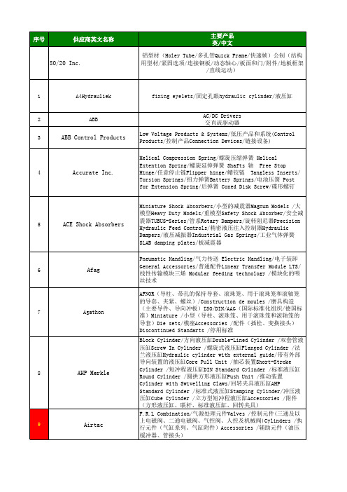
/80/20-Inc./?prjpathinfo=8020//abb/?prjpathinfo=abb/abb_ww/?prjpathinfo=abb_ww/ACE-Shock-Absorbers/?prjpathinfo=ace_sto/agathon/?prjpathinfo=agathon/airtac/?prjpathinfo=airtac/Alfa-Laval/?prjpathinfo=alfalaval//AMF-ANDREAS-MAIER-GMBH-CO-KG/?prjpathinf/Aoki-Mecha-Tech/?prjpathinfo=aoki//apore/?prjpathinfo=apore/asahi/?prjpathinfo=asahi/ATEK-Antriebstechnik/?prjpathinfo=atek/ /Baldor-Dodge-Reliance/?prjpathinfo=baldor//balluff/?prjpathinfo=balluff/bando/?prjpathinfo=bando/belden/?prjpathinfo=belden/BENE-INOX-Raccords-Robinetterie-Accessoires-de-Tuyauterie/?prjpat/bimba/?prjpathinfo=bimba/Bosch-Rexroth/?prjpathinfo=bosch_rexroth/Boteco/?prjpathinfo=boteco//Brauer/?prjpathinfo=brauer//Buerkert/?prjpathinfo=buerkert//Bühler-Motor/?prjpathinfo=buehler_motor/ /Burger-Brown/?prjpathinfo=burger_brown//CA-BE/?prjpathinfo=ca_be//camozzi/?prjpathinfo=camozzi//captron/?prjpathinfo=captron//CCVI-Japan/?prjpathinfo=tashico//CKD/?prjpathinfo=ckd//CMB-Cilindri/?prjpathinfo=cmbcilindri/ /Codipro/?prjpathinfo=codipro//Colder/?prjpathinfo=colder//COMAT/?prjpathinfo=comat//Concens/?prjpathinfo=concens//Cumsa/?prjpathinfo=cumsa//CutTOOLity/?prjpathinfo=cuttoolity//DAI-ICHI-SOKUHAN-WORKS-CO./?prjpathinfo=issoku/ /Danly/?prjpathinfo=danly//DE-STA-CO/?prjpathinfo=destaco//DIM/?prjpathinfo=dim//Dirak/?prjpathinfo=dirak//D-M-E/?prjpathinfo=dme//DMS-Diemould-UK/?prjpathinfo=dms_diemould//DMS-Diemould-Service/?prjpathinfo=dms_diemould_na//Domino-Modul/?prjpathinfo=domino_modul//Duplomatic/?prjpathinfo=duplomatic//DYMCO,-LTD./?prjpathinfo=dymco//DZ-Trasmissioni/?prjpathinfo=dztrasmissioni//Eaton-Walterscheid/?prjpathinfo=eaton_walterscheid//Eaton's-Moeller%AE-series/?prjpathinfo=moeller//Eberhard/?prjpathinfo=eberhard//EGIS/?prjpathinfo=egis//Elesa/?prjpathinfo=elesa//EMB/?prjpathinfo=emb//EMILE-MAURIN-El%E9ments-d'Assemblage-Boulonnerie-Visserie/?prjpat/EMILE-MAURIN-El%E9ments-Standard-M%E9can/EMILE-MAURIN-Produits-M%E9tallurgiques/?prjpathinfo=emile_maurin_/EPS/?prjpathinfo=eps//EPSON/?prjpathinfo=epson//ERO/?prjpathinfo=ero//Ewikon/?prjpathinfo=ewikon//FAG/?prjpathinfo=fag//Farbo/?prjpathinfo=farbo//Fath/?prjpathinfo=fath//Febrotec/?prjpathinfo=febrotec//Ferry-Produits/?prjpathinfo=ferry_produits//Festo/?prjpathinfo=festo//Fibro/?prjpathinfo=fibro//Finder/?prjpathinfo=finder/ /Flexa/?prjpathinfo=flexa//FlexLink/?prjpathinfo=flexlink//Fluro/?prjpathinfo=fluro//Foehrenbach/?prjpathinfo=foehrenbach//Franke/?prjpathinfo=franke//FUJIKURA-RUBBER/?prjpathinfo=fujikura_ru/FYH-NIPPON-PILLOW-BLOCK-CO.,-LTD./?prjpathinfo=nippon_pb//Ganter/?prjpathinfo=ganter//GHV/?prjpathinfo=ghv//Giroud/?prjpathinfo=giroud//Grip/?prjpathinfo=grip//Grob-GmbH-Antriebstechnik/?prjpathinfo=grob_antriebstechnik/ /Groschopp/?prjpathinfo=groschopp//GSB-OILLESS/?prjpathinfo=gsb_oilless//Guizhou-Aerospace/?prjpathinfo=guizhou_a/Gutekunst-Federn/?prjpathinfo=gutekunst//Gysin/?prjpathinfo=gysin//Halder/?prjpathinfo=halder//Halfen/?prjpathinfo=halfen//halstrup-walcher/?prjpathinfo=halstrup_w/Hamilton-Caster/?prjpathinfo=hamiltoncaster//Hammer-Caster/?prjpathinfo=hammer_caster//Harmonic-Drive-Systems,Inc./?prjpathinfo=hardrive/ /HARTING/?prjpathinfo=harting//HATLAPA/?prjpathinfo=hatlapa//HBM/?prjpathinfo=hbm//Hettich/?prjpathinfo=hettich//HEB/?prjpathinfo=heb//Hephaist/?prjpathinfo=hephaist//HEPHAIST-SEIKO-CO.,LTD./?prjpathinfo=hephaist/ /Heiss/?prjpathinfo=heiss//HPC/?prjpathinfo=hpc//Hub-City/?prjpathinfo=hubcityinc//Huelsen/?prjpathinfo=huelsen//Hugro/?prjpathinfo=hugro//Hummel/?prjpathinfo=hummel//Hydropneu/?prjpathinfo=hydropneu//Hypertac/?prjpathinfo=hypertac//IAI/?prjpathinfo=iai//Idec/?prjpathinfo=idec//IEF-Werner/?prjpathinfo=ief_werner//IFM-Electronic/?prjpathinfo=ifm_electronic/ /IGUCHI-KIKO-CO.,-LTD./?prjpathinfo=isb/ /Igus/?prjpathinfo=igus//IKO-Nippon-Thompson/?prjpathinfo=iko//IMS-UNIVERSAL-Fastening-elements/?prjpat /inkoma/?prjpathinfo=inkoma//Inocon/?prjpathinfo=inocon//Intercom/?prjpathinfo=intercom//IPR/?prjpathinfo=ipr//ISOLOC/?prjpathinfo=isoloc//Italcuscinetti/?prjpathinfo=italcuscinetti/ /IWATA-MFG.-CO.,-LTD./?prjpathinfo=iwata/ /JTEKT-Corporation-Koyo/?prjpathinfo=koyo/ /Kabelschlepp/?prjpathinfo=kabelschlepp/ /Katayama/?prjpathinfo=kana//Kerb-Konus/?prjpathinfo=kerb_konus/ /Kern/?prjpathinfo=kern//KHK-Kohara-Gear/?prjpathinfo=khk/ /KIPP/?prjpathinfo=kipp//KIPP-USA/?prjpathinfo=kipp_usa/ /Kistler/?prjpathinfo=kistler//Komax/?prjpathinfo=komax//Konstandin/?prjpathinfo=konstandin/。
三维集成技术的现状和发展趋势
三维集成技术的现状和发展趋势吴际;谢冬青【摘要】The definition of 3D technologies is given in this paper. A clear classification of variety 3D technologies is pro-posed,in which there are 3D packaging,3D wafer-level packaging,3D system-on-chip,3D stacked-integrated chip and 3D in-tegrated chip. Two technologies (3D system-on-chip and 3D stacked-integrated chip) with application prospect and their TSV technical roadmap are analyzed and compared. 3D integrated circuit's some problems in the aspects of technology,testing,heatdissipation,interconnection line and CAD tool are proposed and analyzed. Its research prospect is pointed out.%给出了三维技术的定义,并给众多的三维技术一个明确的分类,包括三维封装(3D-P)、三维晶圆级封装(3D-WLP)、三维片上系统(3D-SoC)、三维堆叠芯片(3D-SIC)、三维芯片(3D-IC)。
分析了比较有应用前景的两种技术,即三维片上系统和三维堆叠芯片和它们的TSV技术蓝图。
给出了三维集成电路存在的一些问题,包括技术问题、测试问题、散热问题、互连线问题和CAD工具问题,并指出了未来的研究方向。
虚拟现实技术——VRML篇
虚拟现实技术――VRML篇一、VRML介绍1.什么是VRML?VRML是“Virtual Reality Modeling Language”的缩写形式,意思是“虚拟现实造型语言”。
第一代Web是以HTML为核心的二维浏览技术,受HTML语言的局限性,VRML 之前的网页只能是简单的平面结构,而且实现环境与参与者的动态交互是非常烦琐的。
第二代Web是以VRML为核心的三维浏览技术。
第二代Web把VRML与HTML、Java、媒体信息流等技术有机地结合起来,形成一种新的三维超媒体Web。
VRML是用来描述三维物体及其行为的,可以构建虚拟境界(Virtural World), 可以集成文本、图像、音响、MPEG影像等多种媒体类型,还可以内嵌用Java、ECMAScript等语言编写的程序代码。
以VRML为核心构建的虚拟世界中用户如身处真实世界,可以和虚拟物体交互,人们可以以习惯的自然方式访问各种场所,在虚拟社区中“直接”交谈和交往。
事实上,目前采用VRML技术取得成功的案例已经很多,例如探路者到达火星后的信息就是利用VRML在因特网上即时发布的,网络用户可以以三维方式随探路者探索火星。
2.VRML的工作原理VRML定义了一种把3D图形和多媒体集成在一起的文件格式。
从语法角度看,VRML文件是显式地定义和组织起来的3D多媒体对象集合;从语义角度看,VRML 文件描述的是基于时间的交互式3D多媒体信息的抽象功能行为。
VRML文件描述的基于时间的3D空间称为虚拟境界(Virtual World),简称境界,所包含的图形对象和听觉对象可通过多种机制动态修改。
VRML文件可以包含对其他标准格式文件的引用。
可以把JPEG、PNG和MPEG 文件用于对象纹理映射,把WAV和MIDI文件用于在境界中播放的声音。
另外,还可以引用包含Java或ECMAScript代码的文件,从而实现对象的编程行为。
VRML使用场景图(Scene Graph)数据结构来建立3D实境,VRML的场景图是一种代表所有3D世界静态特征的节点等级:几何关系、质材、纹理、几何转换、光线、视点以及嵌套结构。
多晶材料织构的又一表示法——三维取向分布函数(odf)分析法

多晶材料织构的又一表示法——三维取向分布函数(odf)分析法
近年来,随着多晶材料的迅速发展,多晶织构的表示方法亦在不断完善。
目前,除了常用的晶体布朗定律及其经典的Fourier变换方法外,另一种描述多晶织构的表示法─三维取向分布函数(odf)分析法也逐渐成为研究多晶材料织构的重要参考
依据。
首先,odf分析法针对每一个取向拟合一个单独的参数,确定材料在每个方向
上的取向分布,而这些参数便是其三维取向分布函数,因此,这种方法经过拟合可比较准确地描述多晶材料的取向结构,可以在呈现更新的结构特征方面发挥作用。
此外,利用odf分析可以更好的获取非等向性的研究结果,从而可以更准确地
描述材料的织构特性,在预测材料力学行为时发挥重要作用。
而且,此外此种分析可以提供非常明确的结构信息,可以帮助解释化学与多晶织构之间的相互影响。
总而言之,odf分析是多晶织构表示法中重要的参考依据,它既可以准确描述
材料取向结构,又能提供易于理解的结构信息,从而帮助进一步研究多晶材料的力学特性。
因此,odf分析法的开发和应用具有重要的意义。
- 1、下载文档前请自行甄别文档内容的完整性,平台不提供额外的编辑、内容补充、找答案等附加服务。
- 2、"仅部分预览"的文档,不可在线预览部分如存在完整性等问题,可反馈申请退款(可完整预览的文档不适用该条件!)。
- 3、如文档侵犯您的权益,请联系客服反馈,我们会尽快为您处理(人工客服工作时间:9:00-18:30)。
Samsung’s Stacked Flash Memories
Samsung Electronics
A small foot-print wafer-level processed stack package (WSP) 16Gbit memory prototype sample (Apr., 2006).
ASTRI Proprietary
Toshiba Image Sensor with TSV
Production started in January 2008. TSV Technology
Reduced wire bond substrate area by mounting components directly on the wafer and running electrodes through the vias on the circuit board, attached with solder balls; Reduced pixel size, contributing to 64% smaller size module.
ASTRI Proprietary
Functionality Motivation
Heterogeneous Integration
Integrate different functional chips (RF, memory, logic, MEMS, imagers, etc.)
8
ASTRI Proprietary
• Smaller capacitor not needed; • Shorter wires, leading to less delay.
DRAM
• Under 65nm may not lower cost; • Difficulty in large DRAM.
2009 – 2010: Elpida
6
Applications
WLAN; Source: IBM Cellular applications; High-performance server and supercomputer chips.
Benefits
40% better power efficiency in SiGe-based wireless products; Increases processor speed by reducing grid power consumption up to 20%; Allows stacking of high-performance chips, e.g., processor-onprocessor or memory-on-processor.
4
More than Moore
• Reduce wire length to shorten delay; • Stacked transistors to achieve faster CMOS circuit.
CPU
• No suitable photolith system available; • Unstable cell operation.
Outline
Background & Motivation Technology Development Status Worldwide Market Development Status & Forecast ASTRI’s R&D in 3D Integration
Package-on-Package (PoP) Through-Silicon-Via (TSV)
ASTRI Proprietary
Performance Motivation
TSV Chip (IBM: Apr. 13, 2007)
Shorten data-travel distances by up to 1000X; Allow for 100X more pathways than 2D chips; Sample 2Q’07 and production 2008.
CMOS Imaging Sensor
CIS 1Q’07 Market Share
Hale Waihona Puke 14Source: Tech System Research ASTRI Proprietary
ST’s TSV Interconnect
2MPixel (2.6x2.6um pixel) CIS: Leti & ST (Jun. 2007)
2
Summary Acknowledgements
ASTRI Proprietary
3
Background & Motivation
ASTRI Proprietary
Technology Challenges
Moore
• Wire delay limits chip speed; • Unclear if CMOS circuit possible under 32nm.
Cost Motivation
100
M an u f. C o st / b it (16-G b it = 100)
90 80 70 60 50 40 5Xnm Conventional smaller design rule 4X~3Xnm 3Xnm 3X ~2Xnm
9
• Limit for further reduction; • No photolith system available; • Cell operation unstable.
• Lower manuf. Cost even with same 90nm; • Stacking bigger DRAM by different processes.
DRAM + Logic 90nm
Problems with smaller design rule Advantages using 3D integration
Assembly Compatibility
Available in both wire bond and BGA formats.
ASTRI Proprietary
3D System Roadmap
17
Source: Yole Develop. 2007
ASTRI Proprietary
18
Market Development Status & Forecast
NAND Flash Capacity (Gbit)
ASTRI Proprietary
10
Technology Development Status Worldwide
ASTRI Proprietary
Flash Memory Market Evolution
Flash Memory has many applications: PDAs, laptop computers, digital audio players, digital cameras and mobile phones, etc.
End 2005: Sony
ASTRI Proprietary
65-45nm
32-22nm
5
What is 3D Packaging?
2D Interconnect Die Stacking
SOC Solution Package-on-Package (PoP)
3D Interconnect Through Silicon Via (TSV)
New Architecture
Photosensitive elements are placed on top of the circuit read-out leading to ~ 100% light fill factor
Tessera’s WLC Technology
Size Reduction
ASTRI Proprietary
Form Factor Motivation
Major Requirements of Future Electronic Products
Smaller, faster, thinner, & affordable, etc.;
7
Connect anywhere and anytime to information, entertainment, communication, monitoring and control.
< 2Xnm 30
2D App.
20
3D Int. Moore R
3D integration of 2 memory cells
Moore rule continuity (cost drops ~40% / per bit with capacity increase.
10
16 32 64 128 256
2011 – 2015: Intel / IBM
• Use proven photolith system; • Stable cell operation.
NAND
• Difficult to make smaller capacitor; • Longer wire delays.
2011 – 2015: Samsung
15
Photosensitive elements are placed on top of the CMOS circuit readout, allowing 100% light collection across the CMOS imager full die area; Key idea is to use hydrogenated amorphous silicon as the photosensitive layer element.