使用说明书-Shimano
SHIMANO 变速器(手变)说明书

(English)DM-ST0001-05Dealer's ManualMTB RAPIDFIRE Plus ST-M4000ST-M4050ST-T4000ST-T3000ST-M370EZ-FIRE Plus ST-EF65ST-EF51ST-EF51-AST-TX800ST-EF41ST-EF40ROADTiagraST-4600ST-4603SORAST-3500ST-3503 SHIMANO Claris ST-2400ST-2403 SHIMANO 2300 ST-2300ST-2303 TourneyST-A070ST-A073Non-SeriesST-R460ST-R350ST-R353ST-R240ST-R243•This dealer's manual is intended primarily for use by professional bicycle mechanics.Users who are not professionally trained for bicycle assembly should not attempt to install the components themselves using the dealer's manuals.If any part of the information on the manual is unclear to you, do not proceed with the installation. Instead, contact your place of purchase or a local bicycle dealer for their assistance.•Make sure to read all instruction manuals included with the product.•Do not disassemble or modify the product other than as stated in the information contained in this dealer's manual.•All dealer's manuals and instruction manuals can be viewed on-line on our website ().•Please observe the appropriate rules and regulations of the country, state or region in which you conduct your business as a dealer.•When installing components, be sure to follow the instructions that are given in the instruction manuals.It is recommended to use genuine Shimano parts only. If parts such as bolts and nuts become loose or damaged, the bicycle may suddenly fall over, which may cause serious injury.In addition, if adjustments are not carried out correctly, problems may occur, and the bicycle may suddenly fall over, which may cause serious injury.•Be sure to wear safety glasses or goggles to protect your eyes while performing maintenance tasks such as replacing parts.•After reading the dealer's manual thoroughly, keep it in a safe place for later reference.Be sure to also inform users of the following:•The ST-EF65/ST-EF51/ST-EF51-A (4-finger brake levers) brake levers are equipped with a mechanism to make them compatible with V-BRAKE brakes, which contain a power modulator, cantilever and roller brakes.If the incorrect mode is selected it may cause either excessive or insufficient braking force to occur, which could result in dangerous accidents.Be sure to select the mode in accordance with the instructions given in the table below.C/R positionVVRCC R: Mode position for compatibility with cantilever brakes: Mode position for compatibility with roller brakesV positionVVRCC Rode position for compatibility with V-BRAKE brakeswith power modulatorUse the brake levers with mode switching mechanism in the combinations given above.•Each bicycle may handle differently depending on the product. Therefore, it is important to completely understand and get used to the operation of your bicycle's brake system (including brake lever pressure and bicycle control characteristics).Improper use of your bicycle's brake system may result in a loss of control or a fall, which could lead to severe injury. For proper operation please consult a professional bicycle dealer, or read the owner’s manual. It is important to ride your bicycle and practice braking operation and other basic features, etc.•If the front brake is applied too strongly, the wheel may lock and the bicycle may fall forward, and serious injury may result.•Always make sure that the front and rear brakes are working correctly before riding the bicycle.•The required braking distance will be longer during wet weather. Reduce your speed and apply the brakes early and gently.•If the road surface is wet, the tires will skid more easily. If the tires skid, you may fall off the bicycle. To avoid this, reduce your speed and apply the brakes early and gently.NOTEBe sure to also inform users of the following:•Be sure to keep turning the crank during gear shifting.•Read the dealer's manuals for the front derailleur, rear derailleur, and brake.•Products are not guaranteed against natural wear and deterioration from normal use and aging.•For maximum performance we highly recommend Shimano lubricants and maintenance products.For Installation to the Bicycle, and Maintenance:•When installing the top route type, choose a frame that has three outer casing holders as shown in the illustration at right.Outer casing holder•Use an outer casing which still has some length to spare even when the handlebars are turned all the way to both sides. Furthermore, check that the shifting lever does not touch the bicycle frame when the handlebars are turned all the way.•Use the specified cable and cable guide for smooth operation.•Grease the inner cable and the inside of the outer casing before use to ensure that they slide properly.•Using a frame with internal cable routing is strongly discouraged as it has tendencies to impair the SIS shifting function due to its high cable resistance.•A special grease is used for the gear shifting cable. Do not use premium grease or other types of grease, otherwise they may cause deterioration in gear shifting performance.•If gear shifting adjustments cannot be carried out, check that the rear fork ends are aligned. Also, check if the cable is lubricated and if the outer casing is not too long or short.The actual product may differ from the illustration because this manual is intended mainly to explain the procedures for using the product.MTBInstallation to the handlebarThe tools and tightening torque vary depending on the product. Tighten with a tightening torque that matches the tool size.* Use a handlebar grip with a maximum outer diameter of ɸ32 mm.5 mm Allen key3 mm Allen key< ST-TX800, ST-EF41 >3 mm Allen keyInstallation of the brake cable* Install it as shown in the figure.123ROADInstallation to the handlebarSecure the assembly with the clamp bolt on the outside of the bracket.Pull the bracket cover back and use a 5 mm Allen key to tighten the bolt.Use a handlebar grip with a maximum outer diameter of ɸ 32 mm.Installation of the brake cableROADCable used* Use a cable which still has some length to spare even when the handlebars are turned all the way to both sides.* For information on how to install the brake cable, refer to brake dealer's manual.1.Tilt the lever in (as when shifting) to make it easier to pass the cable through the cable hook.2.Pass the inner cable through.Note:Do not wipe off the grease on the inner cable.Do not let dust adhere on the inner cable.3. Finally, wrap the handlebar with the handlebar tape.MTBCable used(1)Cutting the outer casingWhen cutting the outer casing, cut the end opposite to the end with the marking.After cutting it, make the end round so that the inside of the hole has a uniform diameter.Attach the same outer end cap to the cut end of the outer casing.< Rear lever >1. Set lever (B) to the top position.2. Check the top position on the indicator and install the cable.3.4. Run the inner cable through the outer casing.If the cable hook does not align with the shifting cable hole, press lever (B) again until it does, and then install the cable.< Front lever >Operate lever (B) 2 or more times, check on the indicator that the low position is correct, and then secure the inner cable.Lever (B)1. 2.2< Cable adjuster >The adjustment margin for the cable adjuster is five turns from its fully-tightened position.The adjuster is tightened to the point where it is 1 turn loose of the fully-tightened state.* W 1.* Insert a thin bar-shaped object to remove the outer support spacer.2. Install the outer casing holder cap (sold separately).(sold separately)Note:Install after the adjustment bolt is tightened.The adjustment range for the adjustment bolt is six full turns.2. Pass the inner cable through, and set the outer casing.* Use an outer casing which still has some length to spare even when the handlebars are turned all the way to both sides.Confirm:Make sure the outer casing is firmly set in the outer stopper.Lever stroke adjustmentLever stroke adjustment can be carried out in the following ways.For the tools to be used and adjustment point (s), refer to the table below.(A) Clockwise: The lever strokebecomes smaller.(B) Counterclockwise: The lever strokebecomes larger.When using the reach adjustment block (Pad spacer)Note:When installing the 8-degree reach adjustment block, use an anatomic-type handlebar. If a round-type handlebar is used, the cable stroke may become too short and this can result ininsufficient braking force.Anatomic typeRound type< ST-4600 / ST-4603 / ST-3500 / ST-3503 / ST-2400 / ST-2403 / ST-R460 / ST-R350 / ST-R353 >Pad spacers (A)4°Pad spacers (A) + (B)8°To increase the lever strokeRemove the pad spacer (A) and install the bump rubber.To decrease the lever strokeInsert pad spacer (B) as far as it will go and so that the protrusions fit into the holes in pad spacer (A).* Apply a small amount of grease to the protrusions when installing the pad spacer and the bump rubber.< ST-2300 / ST-2303 >To reduce the reach, remove the bump rubber and replace it with theaccessory pad spacer (two available types: 4° and 8°).8°Replacement method 1. Remove the bump rubber.2. Apply a thin layer of grease to the two protrusions on the pad spacer.3. Press-fit the pad spacer so that the protrusion go as far in as possible.Bump rubberAdjusting the inner cableWhen the cable adjuster is providedThe adjustment margin for the cable adjuster is five turns from its fully-tightened position.The adjuster is tightened to the point where it is 1 turn loose of the fully-tightenedstate.Replacing the inner cable< In the case of a type with a screw-on cover >1. Set lever (B) to the smallest gear/sprocket.3. Pull out the inner cable and install a new inner cable.< In the case of a type with a wire end hooking cap >1. Set lever (B) to the smallest gear/sprocket.2. Remove the wire end hooking cap and install a newinner cable.nd hooking capWire end hooking capScrewdriver #2•For information on how to replace the shifting cable, refer to "Installing the shifting cable".•For information on how to replace the shifting cable with the one without a cable adjuster, refer to "Installing the shifting cable/Cable adjuster."Bracket and lever disassembly* The illustration shows the right-hand lever.< ST-4600 / ST-4603 / ST-3500 / ST-3503 / ST-2400 / ST-2403 / ST-R460 / ST-R350 / ST-R353 >1. First use the Shimano original tool (sold separately) to remove the E-ring. Use part (B) of the Shimano original tool (2) to alignthe E-ring with the direction of removal. Next, set part (A) against the E-ring and remove the E-ring.* Tourney is not equipped with an E-ring.Y6RT66000(1)Shimano original E-ring removal toolWhen removing the E-ring, it may suddenly spring out, make sure there are no persons or objects around before removing it.2. Insert an Allen key or similar tool into the lever axle hole, tap it gently with a plastic hammer to push out the lever axle, whichdisassembles it into the bracket body and the lever body.Bracket bodyLever axleLever bodyNote:Always be sure to remove the lever axle in this direction. If it is removed in the opposite direction, it may damage the bracket body.< ST-2300 / ST-2303 / ST-A070 / ST-A073 >1. First use a 2 mm Allen key to remove the bolt.2. Insert an Allen key or similar tool into the lever axle hole, tap it gently with a plastic hammer to push out the lever axle, whichdisassembles it into the bracket body and the lever body.Lever bodyNote:Always be sure to remove the lever axle in this direction. If it is removed in the opposite direction, it may damage the bracket body.Replacing the return spring< ST-3500 / ST-3503 / ST-2400 / ST-2403 / ST-R350 / ST-R353 > 1. With the spacer fitted in the return spring, push the tip ofthe return spring into the hole in the bearing member, and press in the shaft bushing.* Note that the left and right return springs are different.Set the end of the spring in the hole in the bearing member.HoleSpacer< ST-2300 / ST-2303 >1. Set the return spring on the hole in the bearing member ofthe lever body.* Note that the left and right return springs are different.Set the end of the spring inthe hole in the bearingmember.HoleAssembling the bracket body and lever body< ST-4600 / ST-4603 / ST-R460 >1.Return springNotch2. Align the stud holes, and then set the Shimano original tool(1) in the position shown in the illustration to press-fit the lever axle.•The correct direction for the lever axle is for the E-ring groove to face up.•Check that the surface of the bracket body is flat so theE-ring of the lever axle can fit into the groove properly.E-ring grooveShimano original E-ring removal tool (1):Y6RT660003. Remove the Shimano original tool (1), and then use theShimano original tool (2) to install the E-ring.< ST-3500 / ST-3503 / ST-2400 / ST-2403 / ST-R350 / ST-R353 >1.Set the Shimano original installation tool for the return spring.Shimano original installation tool for the return spring (TL-ST03)2. Align the stud holes, and then set the Shimano original tool(1) in the position shown in the illustration to press-fit the lever axle.•The correct direction for the lever axle is for the E-ring groove to face up.•Check that the surface of the bracket body is flat so the E-ring of the lever axle can fit into the groove properly.Shimano original E-ring removal tool (1):Y6RT660003. Shimano original tool (2) to install the E-ring.Shimano original E-ring removal tool (2):4. with pliers.5. functions properly.Shimano original installation tool for the return spring< ST-2300 / ST-2303 / ST-A070 / ST-A073 >1. Set the Shimano original installation tool for the return spring.Shimano original installationtool for the return spring(TL-ST03)2. Align the stud holes, and then press-fit the lever axle in the position shown in the illustration.Fixed by a lever fixing screwThe correct position is for the round hollowon the lever axle to be aligned with theTightening torque:1 -2 N·m {9 - 17 in. lbs.}3. Remove the Shimano original installation tool for the returnspring with pliers.4. Finally, check that brake operation is normal and the returnspring functions properly.Shimano originalinstallation tool for thereturn springReplacing the bracket coverThe tabs on the bracket cover each fit to a matching slot on thebracket.•Wipe a little rubbing alcohol inside the bracket cover to make installation easier.Please note: specifications are subject to change for improvement without notice. (English) © Feb. 2015 by Shimano Inc. HTR。
shimanoM416中文技术手册
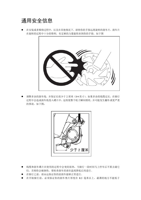
通用安全信息●在安装或者维修过程中,以及在其他情况下,请将你的手指远离旋转的刹车片,刹车片在旋转的过程中十分的锋利,有足够的力量能伤害到你的手指。
如下图●调整多余的刹车线,并保证长度少于2厘米(3/4英寸),如果多余的线缆过长,在骑行过程中会造成刹车线卷入碟片中,这将使整个轮子瞬间锁死,并可能发生翻车或更严重的事故。
如下图:●线缆和刹车碟片在使用的过程中会变的很热,当骑行一段时间马上停车后不要去碰它们。
否则你会被烧伤,要检查刹车的请在温度降低后再进行。
●在骑行之前,请永远保证你的前刹车能够正常进行。
●在开始骑行前,必须保证你的刹车垫片厚度在0.5毫米以上,最薄的地方不能低于0.5mm,如下图:●当你在使用刹车的时听到其他的噪音,这有可能是刹车片损坏或者磨损造成的,在检查完刹车系统确保碟片温度降下来以后,请检查刹车片是否变薄了,或十分有必要更换新的刹车片,请通过刹车片指示器看提示是否需要更换新的刹车片,如下图:●请小心,不要将任何的的油脂进入到刹车片和碟片上,如果有油脂和其他油脂类物质进入到刹车片上,你需要重新更换刹车片,如果有相关油脂和润滑油进入到碟片上,你需要清理碟片。
如果不这样做的话,刹车系统将不会正确的工作。
●检查刹车线是否还能进行工作,检查刹车线是否有弹性和伸缩性,如果线缆磨损或者其它问题,十分有必要更换新的线缆,如果不这样做,刹车系统将不会正常的工作。
●长距离的在雨中骑行,为了使刹车能够更好的工作,请控制好你的车速,这样使刹车x系统能够尽早的完成并确保您的安全。
●如果路面十分湿滑,会加速磨损刹车线和刹车片,并造成刹车线加热磨损或者失灵,如果发生了这种情况这时候你需要尽快跳下车子,为了避免这些,请减小你的速度并提前做好刹车。
●如果快拆装置和碟片处在用一面,有可能造成碟面和快拆接触的可能,所以请检查并尽可能的处理这个问题。
●了解刹车的工作系统是十分必要的,这样会尽可能的会减少事故的发生,你可以从相关操作手册或者及自行车购买商店了解到这些技能,并且在骑行训练过程中适当的进行一些练习。
自行车中文说明书Shimano

自行车中文说明书——Shimano CN-7701/CN-93/CN-73山地链条安装和维护Shimano CN-7701/CN-93/CN-73山地链条安装和维护一.基础信息CN-7701/CN-93/CN-73都是9速链条,只能使用加强连接栓(reinforced connecting pin)来连接链条。
有两种不同规格的加强连接栓,所使用的工具也不同,不正确的搭配会导致链条损坏乃至断裂。
请根据下表进行选择:链条加强连接栓工具9速链条如:CN-7701/CN-HG93TL-CN31/TL-CN228/7/6速链条如:CN-HG50/CN-IG51TL-CN31/TL-CN22和TL-CN30/TL-CN21要截断链条时,注意不要在加强连接栓和末端栓(end pin)的地方进行:二.连接步骤:将链条两端拉在一起,建议外侧一端在前(按传输方向),如图A。
这比相反方向(如图B)的强度要高:插入加强连接栓:用工具将连接栓按进链条内:到位后的样子:用工具拔掉多余的部分:注意:固定栓在链条两侧的突出程度要一样。
三.维护链条上油前先清洗干净。
不要使用酸性材料做清洗剂。
洗完后用清水除去清洗剂。
当链条完全干燥后再上油。
定期的润滑能延长链条的使用寿命。
润滑油要上在链条的关节处,并让其渗进去。
行车中文说明书——Shimano CS-M970/CS-M760/CS-M580山地飞轮安装和维护Shimano CS-M970/CS-M760/CS-M580山地飞轮安装和维护一.规格表XTRDEORE XTDeore LX型号CS-M970CS-M760CS-M580类型HG Cassette Sprocket速级9链条Super Narrow HG for 9-speed齿数(ba)11-32T(be)11-34T(bd)12-34T(aq)11-32T(as)11-34T(ar)11-32T(au)11-34TSprocket MaterialSteel-5/Ti-4steelsteelSprocket FinishNickel/Titaniumchrome platedpearl bright finish齿数:11-32T:11-12-14-16-18-21-24-28-3211-34T:11-13-15-17-20-23-26-30-3412-34T:12-14-16-18-20-23-26-30-34二.安装(1).对齐安装位置每个飞轮齿片有标记的那面要装在外侧。
渠道Shimano的UM-28J0A-002-06用户手册说明书

请不要操作E-Thru手柄。碟盘非常锋利,所以可能导致重伤。
• 在使用刹车的过程中,刹车卡钳和碟盘将变得非常热。在骑车后进行E-Thru 系统使用作业时,有烫伤的危险,所以请确认刹车部件是否充分冷却。
• 在安装作业前,请在清除后叉端片的孔和轴螺帽、轴开口部的垃圾和灰尘 后方可作业。垃圾和灰尘将导致E-Thru系统安装不适当,花鼓和轴的不适当 安装将导致车轮脱落而负重伤。
图1
图2
各部名称
轴螺帽
后叉端片
花鼓肩
轮轴
操作
注意
• E-Thru手柄的操作请务必用手进行。绝对不要进行用锤子等放倒的操作。将 导致E-Thru系统、车架破损。
E-Thru花鼓是指?
这是通过花鼓的E-Thru手柄一个操作,就可以简单地固定和解除车轮的构造。
E-Thru花鼓的功能
斜拉E-Thru手柄至CLOSE位置,固定车架以确保车轮处于正确位置。
骑车前的日常检查项目
骑车前请检查下面所记载的项目。当有异常时,建议在销售店或代理店进行 检查或更换作业。
• 车轮是否正确安装到车架上? • E-Thru手柄是否推至CLOSE位置?
快速检查
抬起自行车,使车轮离开地面。请如图1所示向下猛烈敲击轮胎的上部数次。 接着如图2所示向两侧晃动车轮,确认完全无松动。这种检查方法并不是确认 E-Thru手柄是否充分拧紧的方法。若不明确E-Thru手柄是否正确拧紧,请在仔 细阅读该使用说明书的“车轮的安装方法”一项的基础上,正确固定并纠正后 方可骑车。
• 如果REAR E-THRU 12mm安装不当,骑行时会造成车轮脱离并导致严重身体
伤害。 • 当E-Thru手柄位于车架的左侧(碟盘侧)时, 图1
请注意碟盘与E-Thru手柄的干扰(图1)。此
Shimano变速手柄 UM-67R0A-003 用户手册说明书

(Chinese)UM-67R0A-003用户手册变速手柄https://目录重要提示 (3)重要安全信息 (4)注意 (5)骑车前的例行检查项目 (6)部件名称 (7)操作方法 (8)操作方法(RAPIDFIRE PLUS MONO手柄) (10)重要提示重要提示对于用户手册中未包含的产品安装、调节和更换相关信息,请咨询购买地或经销商。
为专业和具备熟练经验的自行车技师提供的经销商手册,可参见我们的网站(https://)。
为了安全起见,在使用前请务必仔细阅读“用户手册”的基础上正确使用,并将其妥善保管,以便能够随时查阅参考。
为避免对人员造成伤害以及对设备和周围环境造成物理损坏,请务必遵守以下事项。
错误使用产品时可能产生的危险和损坏按等级进行区分说明。
未依说明使用会导致重伤甚至死亡。
警告未依说明使用可能导致重伤甚至死亡。
小心未依说明使用可能导致人员受伤或设备和周围环境受到物理损坏。
重要安全信息重要安全信息不得对产品进行拆卸或改动。
否则会造成产品运行不正常,而且可能会造成您突然摔落,并严重受伤。
注意注意进行手柄操作时,请务必持续转动曲柄臂。
另请阅读前拨链器和后拨链器用户手册。
因正常使用及老化所产生的自然磨损及性能劣化不在保修范围内。
为了获得最大的性能,我们强烈推荐 SHIMANO 润滑油和保养产品。
骑车前的例行检查项目骑车前的例行检查项目骑车前请检查下面所记载的项目。
如果发现任何问题,请咨询购买地或经销商。
变速是否顺利?手柄是否被牢固地安装到了车把上?操作过程中是否出现了任何异常噪音?部件名称前侧后侧曲柄臂操作方法变速操作进行手柄操作时,请务必持续转动曲柄臂。
操作时的注意事项完成变速后,手柄A和手柄B将返回初始位置。
右侧手柄操作飞轮片移动数由手柄行程决定。
若要移动一个飞轮片,请将手柄移动至位置(1)。
若要移动两个飞轮片,请将手柄移动至位置(2)。
(1) 移动一个飞轮片示例:从第3个飞轮片移动至第4个飞轮片(2) 快速移动两个飞轮片示例:从第3个飞轮片移动至第5个飞轮片手柄A:从最小飞轮片侧移动到最大飞轮片侧A 初始位置手柄B:从最小飞轮片侧移动到最大飞轮片侧示例:从第4个飞轮片移动至第3个飞轮片左侧手柄操作初始位置手柄A:从最小链轮片侧移动到最大链轮片侧手柄A:从最大链轮片侧移动到最小链轮片侧初始位置操作方法(RAPIDFIRE PLUS MONO手柄)使用一个手柄操作。
SHIMANO 自行车零配件说明书

(English)DM-TORQUE-00 Dealer's ManualTorque ChartDURA-ACEBR-R9270 BR-R9170 BR-R9200 BR-R9210 BR-R9100 BR-R9110 ST-R9100 RD-R9100 FD-R9100 WH-R9200 WH-R9100 WH-R9270 WH-R9170 CS-R9200-12 CS-R9100 FC-R9200 FC-R9100 FC-R9200-P FC-R9100-PBB-R9100SM-RT900ST-R9120ULTEGRABR-R8170BR-R8070BR-R8100BR-R8110BR-R8000BR-R8010ST-R8000RD-R8000FD-R8000WH-R8170CS-R8100-12CS-R8000CS-HG800-11FC-R8100FC-R8000FC-R8100-PSM-BBR60SM-RT800ST-R8020ST-R8025SHIMANOSM-RT70SHIMANO 105BR-R7170BR-R7070BR-R7000BR-R7010ST-R7000RD-R7000FD-R7000CS-R7100-12CS-R7000CS-HG700-11FC-R7100FC-R7000ST-R7020ST-R7025DURA-ACE Di2ST-R9250RD-R9250FD-R9250ST-R9270ULTEGRA Di2ST-R8150RD-R8150FD-R8150ST-R8170SHIMANO 105 Di2RD-R7150FD-R7150ST-R7170General (Torque)Torque ChartContents Notice (3)ROAD (4)Hydraulic Disc Brake Caliper (4)Dual Pivot Caliper Brake (5)DUAL CONTROL LEVER (6)Rear Derailleur (7)Front Derailleur (7)Wheel Set (8)Wheel Set (Disc Brake) (8)Cassette (8)Crankset (9)Crankset with Power Meter (9)Threaded Bottom Bracket (10)Disc Brake Rotor (10)NoticeThis content has been compiled for the higher-end models in each series.Although every effort has been made to keep the content as up-to-date as possible, we cannot guarantee that the contents are the most current available.For the latest information and other details, refer to the dealer's manual for each product.ROADHydraulic Disc Brake CaliperBR-R9270, BR-R9170, BR-R8170, BR-R8070, BR-R7170, BR-R7070Parts Name Model Torque(N·m)ToolsBleed nipple BR-R9170, BR-R8070, BR-R70704 - 77 mm box wrenchBleed screw BR-R9270, BR-R8170, BR-R71704 - 6 3 mm hexagon wrench Caliper fixing screw All 6 - 8 4 mm hexagon wrenchFlare nut BR-R9270, BR-R8170, BR-R71705 - 68 mm spannerBR-R9170, BR-R8070, BR-R70705 - 78 mm hexagon wrenchPad axle BR-R9270, BR-R9170, BR-R8070, BR-R70700.2 - 0.4Slotted screwdriver 0.8 x 4BR-R8170, BR-R7170 2 - 4 3 mm hexagon wrench Hydraulic Disc Brake CaliperDual Pivot Caliper BrakeBR-R9200, BR-R9210, BR-R9100, BR-R9110, BR-R8100, BR-R8110, BR-R8000, BR-R8010, BR-R7000, BR-R7010Parts Name Model Torque(N·m)ToolsInner cable fixing screw All 6 - 8 4 mm hexagon wrench Mounting screw BR-R9210, BR-R9110, BR-R8110, BR-R8010, BR-R70105 - 7 4 mm hexagon wrenchRecessed nut BR-R9200, BR-R9100, BR-R8100, BR-R8000, BR-R70008 - 10 5 mm hexagon wrench Shoe fixing screw All 1 - 1.5 2 mm hexagon wrench Shoe fixing screw unit All 5 - 7 4 mm hexagon wrench Dual Pivot Caliper BrakeDUAL CONTROL LEVERST-R9250, ST-R9100, ST-R8150, ST-R8000, ST-R7000Parts Name Model Torque(N·m)ToolsClamp screw All 6 - 8 5 mm hexagon wrench Name plate fixing screws ST-R9100, ST-R8000, ST-R70000.15 - 0.2Screwdriver[#1]Unit cover fixing screws ST-R9100, ST-R8000, ST-R70000.2 - 0.25Screwdriver[#1]ST-R9270, ST-R9120, ST-R8170, ST-R8020, ST-R8025, ST-R7170, ST-R7020, ST-R7025Parts Name Model Torque(N·m)ToolsBattery holder fixing screw ST-R9270, ST-R8170, ST-R71700.4Slotted screwdriver 0.8 x 4Bleed screw ST-R9270, ST-R8170, ST-R71700.5 - 0.7 2.5 mm hexagon wrenchST-R9120, ST-R8020, ST-R8025, ST-R7020, ST-R70250.5 - 0.7 2 mm hexagon wrench Clamp screw All 6 - 8 5 mm hexagon wrench Flange flare nut All 5 - 68 mm spannerLid fixing screw ST-R9120, ST-R8020, ST-R8025, ST-R7020, ST-R70250.8Hexalobular [#8]Name plate fixing screws ST-R9120, ST-R8020, ST-R8025, ST-R7020, ST-R70250.15 - 0.2Screwdriver[#1]Unit cover fixing screws ST-R9120, ST-R8020, ST-R8025, ST-R7020, ST-R70250.2 - 0.25Screwdriver[#1]DUAL CONTROL LEVERRear DerailleurRD-R9250, RD-R9100, RD-R8150, RD-R8000, RD-R7150, RD-R7000Parts Name Model Torque(N·m)ToolsBracket axle (Direct mount type)All8 - 10 5 mm hexagon wrenchInner cable fixing screw RD-R9100, RD-R8000,RD-R70006 -7 4 mm hexagon wrench Mounting screw All8 - 10 5 mm hexagon wrench Plate stopper pin RD-R8150, RD-R7150 1 - 1.1Cross head screwdriver [#2] Pulley screw RD-R9250 2.5 - 5 3 mm hexagon wrench Pulley set RD-R8150 2.5 - 5 3 mm hexagon wrenchRetaining screw RD-R9250, RD-R8150,RD-R71500.9 - 1.2Hexalobular [#10]RD-R9100, RD-R8000,RD-R70001Hexalobular [#10]Tension & Guide Pulley Set RD-R9100, RD-R8000,RD-R7150, RD-R70002.5 - 5 3 mm hexagon wrench Tension pulley All 2.5 - 5 3 mm hexagon wrench Front DerailleurFD-R9250, FD-R9100, FD-R8150, FD-R8000, FD-R7150, FD-R7000Parts Name Model Torque(N·m)ToolsInner cable fixing screw FD-R9100, FD-R8000, FD-R70006 -7 4 mm hexagon wrench Mounting screw All 5 - 7 5 mm hexagon wrench Rear DerailleurWheel SetWH-R9200, WH-R9100Parts Name Model Torque(N·m)ToolsFreewheel body fixing screw WH-R910045 - 5014 mm hexagon wrench Lock nut (FREEHUB)WH-R920016 - 20 5 mm hexagon wrench +17 mm hub spannerWH-R910015 - 17 5 mm hexagon wrench x 2 Lock nut (Front hub)WH-R920015 - 17 5 mm hexagon wrench +22 mm hub spannerWH-R9100 5 mm hexagon wrench x 2 Wheel Set (Disc Brake)WH-R9270, WH-R9170, WH-R8170Parts Name Model Torque(N·m)ToolsDisc brake rotor lock ring WH-R9270, WH-R817040TL-LR15 + 24 mmhub spanner /adjustable wrenchWH-R9170TL-FC36 Freewheel body WH-R9170, WH-R8170147 - 200TL-FH15Lock nut (FREEHUB)WH-R927016 - 2017 mm hub spannerx 2WH-R9170, WH-R817017 - 22Lock nut (Front hub)All18 - 2017 mm hub spanner+ 22 mm hubspanner CassetteCS-R9200-12, CS-R9100, CS-R8100-12, CS-R8000, CS-HG800-11, CS-R7100-12, CS-R7000, CS-HG700-11Parts Name Model Torque(N·m)ToolsLock ring CS-R9200-12, CS-R8100-12, CS-R7100-1230 - 50TL-LR10 / TL-LR15 +adjustable wrenchCS-R9100, CS-R8000, CS-HG800-11, CS-R7000, CS-HG700-11TL-LR15 + adjustable wrenchCranksetFC-R9200, FC-R9100, FC-R8100, FC-R8000, FC-R7100, FC-R7000Parts Name Model Torque(N·m)ToolsChainring fixing screws All12 - 16Hexalobular [#30] Crank mounting screw All0.7 - 1.5TL-FC16 / TL-FC18Left crank arm mounting screws All12 - 14 5 mm hexagon wrench Crankset with Power MeterFC-R9200-P, FC-R9100-P, FC-R8100-PParts Name Model Torque(N·m)ToolsChainring fixing screws All12 - 16Hexalobular [#30]Left crank arm mounting screws All12 - 14 5 mm hexagon wrench Left crank mounting ring All0.7 - 1.5TL-FC40Threaded Bottom Bracket BB-R9100, SM-BBR60Parts Name Model Torque(N·m)ToolsLeft- and right-hand cups BB-R910035 - 50TL-FC24 + TL-FC32TL-FC24 + TL-FC33TL-FC24 + TL-FC36TL-FC34SM-BBR60TL-FC25 + TL-FC32TL-FC25 + TL-FC33TL-FC25 + TL-FC36TL-FC37 Disc Brake RotorSM-RT900, SM-RT800, SM-RT70Parts Name Model Torque(N·m)ToolsDisc brake rotor lock ring All40TL-LR15 + adjustablewrench Threaded Bottom BracketOne Holland, Irvine, California 92618, U.S.A. Phone: +1-949-951-5003High Tech Campus 92, 5656 AG Eindhoven, The Netherlands Phone: +31-402-6122223-77 Oimatsu-cho, Sakai-ku, Sakai City, Osaka 590-8577, JapanPlease note: specifications are subject to change for improvement without notice. (English)© Mar. 2023 by SHIMANO INC. ITP11。
Shimano 鱼竿 使用说明书

安全注意事项接节部难以拔出的时候使用带导环并继/印笼继竿时使用印笼继/逆印笼继竿时禧玛诺(上海)贸易有限公司中国上海市仙霞路137号盛高国际大厦17楼邮编:200051官方网站: 官方微信号:禧玛诺渔具官方微信二维码:鱼竿使用注意事项使用时需注意鱼竿竿身上有触电注意标贴,标贴为了不轻易被剥离施加了涂层,请不要用手去剥,另外,有部分商品的触电注意标贴是印刷上去的。
当产品故障时请联系您购买的店铺或就近的SHIMANO专柜店,如果您不清楚专柜店信息,请致电SHIMANO或通过浏览官方网站了解。
同时,请提供购买时间以及确切的商品名称和商品代码。
使用无导环竿时使用带导环振出竿时使用无导环竿时使用并继/印笼继竿时接节部有沙子进去时使用带导环振出竿时请注意竿梢节、第二节、第三节接节口的折断●如不合理地去拧或撬,都可能造成竿梢折断。
●请确保活动导环固定到位,另外会造成竿梢折断。
使用鱼竿支架/鱼竿固定架时使用实心竿梢鱼竿时使用含渔轮座竿时其他注意事项●鱼竿弯曲时,由于绕线部涂厚漆的部分无法适应鱼竿的弯曲,有时会产生裂纹,但导环和鱼轮座的固定力是完全没有问题的。
目前的生产技术还无法防止这种裂纹,敬请理解。
●●请勿在渔线缠绕的状态下收主线,在鱼竿部分如果施加不合理的力量可能会造成鱼竿折断。
●在取下前堵的时候,请朝着正上方拉拔前堵,如不合理地去拧或撬,都可能造成接节扣部分损坏。
●请勿在渔线缠绕的状态下继续使用。
另外,在使用过程中请不要强行朝垂直方向拉拔,鱼竿可能会因不合理的施加力而造成损坏。
●需要收起鱼竿时请从手把节开始,在收回竿梢节、第二节、第三节等细节时,请把手把节夹在腋下并拿着接节部的上下两端,边拧边塞进去。
●当竿尾贴靠在物体进行收竿时,请贴靠在质地柔软的东西上,从手握竿的地方依次一根一根收纳。
这时请注意不要让竿尾碰到水。
●用腋下夹住鱼竿收竿或出竿时,长竿会相对更易以施加力量,请注意不要太用力避免损伤第二节、第三节的玉口。
禧玛诺自行车轮组使用说明
使用上的注意
另外,务必让用户知悉以下事项 : ••请勿对花鼓内部注入油。否则会引起润滑脂外流。 ••初次使用刹车或骑行1000km后,建议向自行车经销商咨询刹车的调整方法。 ••由于轮圈张贴物会脱落,所以请勿用洗涤液或化学药剂擦拭车轮。 ••一般的碱性爆胎修理剂腐蚀轮圈,可能引起气体泄漏,所以不建议使用。 ••该产品会自然磨损或因正常使用而受损及老化。 •• 由于轮圈接缝上涂抹的气封剂会剥落,因此,请勿使用洗涤液或化学药品等擦拭车轮。 ••有专用的辐条扳手作为选购件供货。
?本车轮并不是为下坡自由骑车而设计的因此受骑车状况的影响可能会使花鼓安装轴上产生裂纹因而引起该轴的折断而造成摔倒事故有时会使骑车者受重伤或者死亡
(Chinese)
DM-WH0001-02
经销商手册
MTB轮组
DEORE XT WH-M785-29 WH-M785-275
目录
重要提示..................................................................................................... 3 为了安全起见............................................................................................. 4 安装............................................................................................................ 6
- 1、下载文档前请自行甄别文档内容的完整性,平台不提供额外的编辑、内容补充、找答案等附加服务。
- 2、"仅部分预览"的文档,不可在线预览部分如存在完整性等问题,可反馈申请退款(可完整预览的文档不适用该条件!)。
- 3、如文档侵犯您的权益,请联系客服反馈,我们会尽快为您处理(人工客服工作时间:9:00-18:30)。
● CJ-S700 闸瓦盒连接器仅适用于 18T– 23T 的链轮。 如果使用 CT-S500 拉链器,请使用专 用的 CS-S500 18T 或 20T 的带链条护 盖的链轮。不得使用其他型号的链轮, 否则,链条有从链轮上脱落的危险。
● 在向链条或链轮注油时,务请注意,不 得将油沾在闸瓦盒连接器的橡胶波纹管 或橡胶盖上。
变速线末端箍帽
5. 将内线从塑料帽处穿入 OT-SP41/SP40 外 线。 ( 杆侧 )
8. 检查外线头是否确实插入变速杆的调节螺 栓内后,将内线固定套件安装在内线上。 安装内线固定螺栓时,建议使用专用工具 TL-S700。
铝帽
塑料帽
如果要剪断外线,请在塑料帽一头剪断,并 保留塑料帽。剪断后,请将断端修正为圆形, 再套上塑料帽。
● 对于正常使用条件下的自然磨耗以及品 质的劣化不予以保证。
SI-6TV0A-001
SL-S700 变速杆 CJ-S700 闸瓦盒连接器
使用说明书
换至高速档(手柄 B)
仅变速 1 档的场合操作到①的位置,变速 2 档 的场合操作到②的位置。如此类推,仅需操作 想变速的档数的位移量。最大可一次变速两个 档次。
显示器套件的交换与组装
变速线末端箍帽
3. 将内线插入卷线器孔中,再将内线穿过变 速线调节螺栓上的孔。然后,拉动内线, 使内线封头嵌入卷线器槽中。
仅在拆除和交换显示器套件时,方需分解或组装。
调至 11 档
■ 拆除
1. 按变速杆 B 十次或十次以上,调至 11 档。 2. 松开并拆下用于固定显示器套件的 3 个盖
5. 用 3 个盖板锁紧螺钉将显示器套件固定。
锁紧力矩 : 0.3 – 0.5 N·m {3 – 5 kgf·cm}
6. 按变速杆 A 和变速杆 B,确认动作是否正常。 如果动作不正常,请重新安装显示器套件, 装时要特别注意上述第 4 步。
变速线的安装
使用单侧封头的变速线。 单侧封头变速线 : OT-SP41/SP40(直径 4mm)
11 6 1
手柄 B 的起始位置 ● 2-WAY RELEASE
( 双方向解除 ) ● MULTI RELEASE
不得分解显示器套件或变速杆。分解会导致 故障。
1. 将变速杆调至 11 档。
从车架上拆下后轮后,如何拆开变速线
变速杆的安装
请按照示意图安装变速杆。
使用最大外径为 34 mm 的把手手柄。
外部支承体支承部
橡胶波纹管
槽
1
将橡胶波纹管放 入槽中
2 装外线座
外线座
橡胶盖
184 mm
将断端修正为圆形。 套上塑料帽。
■ 闸瓦盒连接器侧
6. 将橡胶盖和橡胶波纹管装在外线座上。
橡胶波纹管
外线座 橡胶盖
75 mm 以下 一边装内线固定套件,一边拉内线。
内线
托架
锁紧力矩 : 3.5 – 5.5 N·m {35 – 55 kgf·cm}
锁紧螺钉
1
从车架上拆下后轮,从闸瓦盒连接器上 拆开变速线。
调至 11 档
■ 变速杆侧
2. 松开并拆下变速线末端箍帽。
龙头
2
3 锁紧
4mm 内六角扳手
22.2mm 龙头握把
锁紧力矩 : 4.5 – 6.5 N·m {45 – 65 kgf·cm}
34mm 以下
闸瓦盒连接器
1. 将变速杆调至 11 档。
板锁紧螺钉。
3. 请如示意图所示拆下显示器套件。
盖板锁紧螺钉
2. 请顺时针按下导轮手柄,松开内线。后 面的第 3、4 步,请在此状态下进行操作。
导轮手柄
变速线调节螺栓上的孔
卷线器孔
使用前,请务必阅读此使用说明书,并结合 阅读 SG-S700 花鼓的使用说明书。
显示器套件
转动导轮。
变速杆换档操作
INSTANT RELEASE 机构能在操作的同时进 行飞快解锁。该手柄兼备不管是按或拔,一 次操作便可完成两个档次变速的 2-WAY RELEASE, MULTI RELESE 机构。 在变速结束后松开手指时,手柄 A 和手柄 B 均 会回到手柄的起始位置。
盖板锁紧螺钉
橡胶波纹管
外部支承体支承部
1 从外部支承体支承 部拔出外部支承体。
■ 安装
4. 请确认显示器的指针是否在左侧( 11 的位 置),然后安装显示器套件,方向要笔直向上。 这时,请确认主轴已安装到凸轮孔中,并 且凸轮销已安装到卷线器孔中,然后将从 显示器的下部穿出的指针轴插入凸轮槽中。
托架 槽
SI-6TV0A-001-06
一般安全注意事项
警告
– 为了防止严重伤害 : ● 在安装零件前,请仔细阅读使用说明。
如果零件有松动、磨耗或损坏,会使骑 车人受严重伤害。仅使用纯正禧玛诺更 换用零件。 ● 请仔细阅读该使用说明书,然后加以妥 善保管。
注意
– 为了防止严重伤害 换档时要就轻施加在脚踏板上的压力。假 如你在脚踏板上施加很大压力的情况下强 制换挡,你的脚有可能从脚踏板上滑下, 并且自行车有可能翻倒,这样会导致严重 事故。
塑料帽 拆下塑料帽。
内线固定套件
注 : 该内线固定螺栓是 CJ-S700 专用。 7 段、8 段的固定螺栓无法使用。
10mm
内线锁紧螺母 内线锁紧垫圈 ( 黑色 ) 内线锁紧螺栓 ( 黑色 )
请将内线穿过此孔。
12. 请按示意图将内线装入导轮,将装有橡皮 伸缩管的内线沿闸瓦盒连接器托架上的槽 导入,然后将外部支承体牢固地插入外部 支承体支承部。此时请注意不要损伤橡胶 波纹管。
2 外线座 从槽中抽出
4. 从闸瓦盒连接器的导轮上将内线固定套 件拆下。
指针轴显示器套件来自内线固定套件内线的圆头
卷线器孔
4. 请如图所示,旋转变速线末端箍帽,直至 不能转动。如果拧得太紧,会损坏盖板上 的螺纹。 而且,如果套件盖板变形,会因此而造成 套件盖板与变速杆 A 相碰,导致变速杆 A 不能正常动作。 如果变速杆 A 不能很好复位,请将变速线 末端箍帽稍微松开,使得变速杆 A 和套件 盖板之间有一条缝,然后检查一下变速杆 A 的复位是否改善。
换至低速档(手柄 A) 仅变速 1 档的场合操作到①的位置,变速 2 档 的场合操作到②的位置。如此类推,仅需操作 想变速的档数的位移量。最大可一次变速两个 档次。
11 6 1 手柄 A 的起始位置
变速杆 B
3. 从闸瓦盒连接器的外部支承体支承部拔 出外部支承体。从托架的切槽取下带有 橡皮伸缩管的内线。这时,请注意不要 使橡皮伸缩管受损。