液晶风淋控制器F4H中英文说明书
风淋室控制器使用说明书

风淋室控制器使用说明书软件版本:V10.5.31北京三江汇诚科技有限公司一、控制器简介1.二、控制器画面1.开机画面系统通电后控制器屏幕显示如下画面(可能因版本不同显示方式也有所不同),图1画面内容有控制器名称,控制器软件版本,画面中间部分是控制器检测状态滚动条,最下面是研发厂商信息。
2.主画面在开机画面中,系统开始检测,然后显示如下画面(虚线所示动态显示内容仅供用户参考,可能因版本不同显示方式也有所不同)。
图2此画面中显示信息有:◆通道一开关门状态:显示通道一的门状态,如果指示灯在侧,表示通道一门体正在开启或者已经开启,此状态后面显示的是门将要关闭的倒计时时间;如果指示灯在侧,表示通道一门体正在关闭或者已经关闭,此状态后面显示的是门一开门停留时间。
◆通道二开关门状态:显示通道二的门状态,如果指示灯在侧,表示通道二门体正在开启或者已经开启,此状态后面显示的是门二将要关闭的倒计时时间;如果指示灯在侧,表示通道二门体正在关闭或者已经关闭,此状态后面显示的是门二开门停留时间。
◆风淋状态:显示风淋的开关状态。
如果指示灯是“”状态,则表示风淋正在开启或者已经开启,此状态后面显示的是风淋将要关闭的倒计时时间;如果指示灯是“”状态,则表示风淋正在关闭或者已经关闭,此状态后面显示的是风淋的运行设置时间。
◆照明状态:显示风淋照明灯的开关状态。
如果指示灯是“”状态,则表示照明灯正在开启或者已经开启,此状态后面显示的是照明灯将要关闭的倒计时时间;如果指示灯是“”状态,则表示照明灯正在关闭或者已经关闭,此状态后面显示的是照明灯的开启设置时间。
3.系统设置(显示顺序因版本不同有轻微差距,某些项目需要厂家密码口令)此画面可以设置系统相关时间图3此画面中显示信息有:◆开关门延迟:表示按键反应时间,避免误动作设置单位0.1秒。
◆门到位时间:门从打开到到位的时间。
◆风淋运行时间:风淋电机的运行时间。
图4◆开灯时间:照明灯开启时间。
风淋室控制器说明书
一、概述
风淋室控制器具有门磁监测,门锁、照明灯、送风机自动控制以及中文语音提示功能,面板上有指示灯和管标示风淋室的各个状态以及时间,可以设定风淋吹淋时间长短,以及吹淋后暂停时间长短。
风淋过程中可以急停止键中断吹淋,也可以在任何时候手动按键启动风淋。
1.输入接点
a.供电电源:AC220V
b.进出门开关:门磁开关(关门:闭合,开门:断开)
c.红外线感应开关:无源接点(无人:断开,有人:闭合)
2.输出接点
a.外门电锁:DC12V ≤850mA
b.内门电锁:DC12V ≤850mA
c.风机:220V AC(交流接触器线圈)
d.红外感应器电源:12VDC
e.照明:220V AC, <=100W
f.电源工作指示灯:220V AC
h. 工作指示灯:220V AC。
ST500EFMH智能型电动机控制器技术说明书(英文)
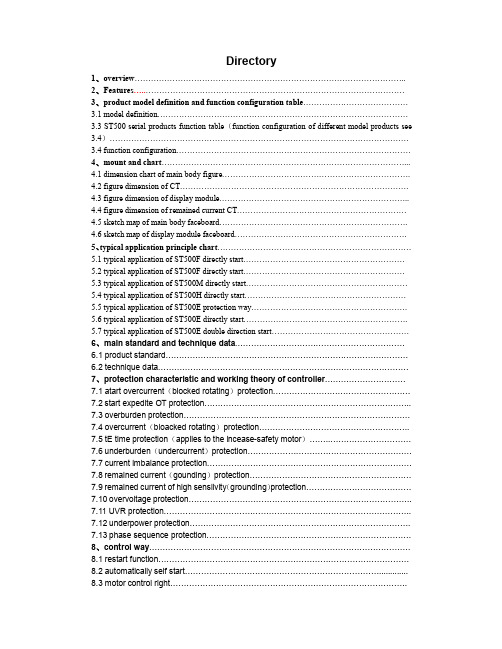
Directory1、overview………………………………………………………………………………………..2、Features…..……………………………………………………………………………………3、product model definition and function configuration table…………………………………3.1 model definition…………………………………………………………………………………3.3 ST500 serial products function table(function configuration of different model products see 3.4)…………………………………………………………………………………………………3.4 function configuration……………………………………………………………………………4、mount and chart………………………………………………………………………………...4.1 dimension chart of main body figure…………………………………………………………….4.2 figure dimension of CT………………………………………………………………………….4.3 figure dimension of display module……………………………………………………………..4.4 figure dimension of remained current CT………………………………………………………4.5 sketch map of main body faceboard…………………………………………………………….4.6 sketch map of display module faceboard……………………………………………………….5、typical application principle chart………………………………………………………………5.1 typical application of ST500F directly start……………………………………………………5.2 typical application of ST500F directly start……………………………………………………5.3 typical application of ST500M directly start……………………………………………………5.4 typical application of ST500H directly start……………………………………………………5.5 typical application of ST500E protection way………………………………………………….5.6 typical application of ST500E directly start…………………………………………………….5.7 typical application of ST500E double direction start……………………………………………6、main standard and technique data………………………………………………………6.1 product standard………………………………………………………………………………6.2 technique data…………………………………………………………………………………7、protection characteristic and working theory of controller…………………………7.1 atart overcurrent(blocked rotating)protection……………………………………………7.2start expedite OT protection…………………………………………………………………..7.3 overburden protection…………………………………………………………………………7.4 overcurrent(bloacked rotating)protection………………………………………………..7.5 tE time protection(applies to the incease-safety motor)……..…………………………7.6 underburden(undercurrent)protection…………………………………………………….7.7 current imbalance protection………………………………………………………………….7.8remained current(gounding)protection……………………………………………………7.9 remained current of high sensiivity(grounding)protection…………………………………7.10 overvoltage protection………………………………………………………………………..7.11 UVR protection………………………………………………………………………………..7.12underpower protection……………………………………………………………………….7.13phase sequence protection………………………………………………………………….8、control way…………………………………………………………………………………….8.1 restart function…………………………………………………………………………………8.2 automatically self start……………………………………………………………….............8.3 motor control right…………………………………………………………………………….1、OverviewThree phase AC asynchronous motor(shortened form motor below)is widely used in each field,it is especially important to ensure the safety control and economically run. Secondary control circuit of traditional motor is generally realized by the hard wiring, high cost,control principle and wiring is complex,workload of design、debug and maintenance is big, when problems appears, it is hard to investigate, protection of traditional motor mainly adopts thermal relay, protection range is narrow(cannot start motor when heavy load)、precision and reliability is low、power consume is big,caused many unnecessary economic loss, ST500 serial intelligent motor controller( shortened form motor below)integrates the technology of Computer、Control、Communication and CRT,also combines many kinds start scheme of motor,monitor the start of motor、run and the electric parameter when abnormal failure happens,utilize the fast disposal ability of microprocessor, according to rating parameter of motor, set time by user, limit value parameter whether normal to motor and failure sort, to correctly judge and distinguish to dispose,ensure the safety run of motor,and through the Chinese LED display、light to indicate、signal output、communication and many other form to inform users.Controller is applicable to the filed of rating frequency 50Hz、rating voltage to690VAC、rating current to 820A, in which motor is used, use of this product simplify the traditional secondary control protection circuit of the motor,provide the perfect motor control and protection method,as the intelligent terminal, it can also realizes the communication group net based on many kinds bus way,realizes the separated control protection and centralized management. The application of controller shorten the project circle, greatly improve the design and production efficiency,also reduces the amount of work that users debug and maintenance.This product adopts modular design,main body、special use current transformer and display module installed separately,volume of product is small, configuration compatible, mount conveniently,can be directly mounted and used in various drawer chest when at 1/4 modulus or above.2、Features●Assistant working power supply supports AC、DC(AC220V、DC220V/110V)●DI supports dry node(weak current DI)or wet node(weak current DI)input,wet node input can select AC or DC power supply.●Control DO supports AC load or DC load,meanwhile “start controlDO ”and“ protect/stop control DO” separate;signal DO is used in self detecting and failure alarm output, etc.●Measuring function is separated as basal measure(current parameter)andaccessorial measure(voltage parameter、remained current)●Supports various control logistic of motor(frequency conversion start、soft start、star-triangle start、two directions start、directly start, etc)●Protection function is separated as basal protection overload、block rotatingovercurrent, etc)and accessorial protection(tE time、remained current、overvoltage、under frequency, etc)●Parameters of protection function can be set at the scene by professional staffaccording to the actual parameters, will not lose when power off.●“tE time protection” meets the standard (GB3836.3-2000)●When extra big short current happens, can lock contactor,through control relay2DO to drive circuit breaker, reliably eliminate the failure.●“resist shaking current” function can ensure the motor continuous run,short timeUVR, lose voltage can realize the motor separate batch to restart(accessorial to select)●Controller can realized the motor start automatically function●4~20mAsimulated signal output can select the various run parameter of motor(accessorial)●Controller supports MODBUS-RTU、PROFIBUS-DP、DeviceNet doubleMODBUS-RTU and many other bus,realize data transmission function (accessorial)●Controller can record current run time、current stop time、accumulated run time、accumulated stop time、accumulated failure time、accumulated operating times,convenient for daily maintenance.●Controller can timely inquiry about I/O status of switching value、current motor runstatus●Controller can record motor eight times failure and failure time mark(standardmatched time clock),realize fast failure position fix.●Friendly human and machine interface:all Chinese LED display(accessorialattachment)3、product model definition and function configuration sheet3.1 model definitionST50 □□─□─□─□┼□┼□┼□┼□ST50 ST500 serial production model1 No communication function2 PROFIBUS-DP3 MODBUS-RTU4 DeviceNet5 Double MODBUS-RTU6 Double PROFIBUS-DPCommunicationF DI is dry node(internal installed DC24Vinput),control DO working powersource is AC220V/380VE DI is dry node(internal installed DC24Vinput),control working power sourceDo working power source is220V/380V,no control logicInput and output working power sourceM DI is wet node(AC220V input),control DOworking power source is AC220V/380VH DI is wet node(DC220V/110V input),control DOworking power source is DC220V/110VControl wayA Directly start controlB Double direction start controlC Frequency conversion start controlF star-triangle start control(two relays)G Resistance voltage reduced controlH Double speed start controlJ Protection wayM Autotransformer reduced voltage to control(two relays)S Soft controlRating current2A5A6.3A25A100A250A500A820ASelected functionV High voltage functionL (grounding) protection function for remained current of high sensitive(need to match special remained current transformer)M2 Analog signal output function(4~20mA)E tE time protection functionS “voltage+restart”function(resist shaking current、UVR、losing voltage restart)Omit will be no selected functionDisplay moduleST522ST522E( no control function)Serial port lineT910-02T915-02T920-02T930-02Remained current transformerZT30 500mA special using remained current transformer, range(50mA~500mA)ZT100 1000mA special using remained current transformer, range(100mA~1000mA)* when select L function, must choose one special using remained current transformerTM electronic arc-control device TMProtection parameter table:itemContentrangeRating power(Pn)250W ~100kW Rating voltage(Ue) 380V ~1200VmotorFull burden current(Ir1)2A(0.5~2A)、5A(1~5A)、6.3A(1.6~6.3A)、25A (6.3~25A )、100A(25~100A)、250A (63~250A )500A(250~500A)、820A (250~820A ) Acting wayalarm 、power offActuating value 20%Ir1~100%Ir1+OFF(close) Under burden protectionDelay time 0s ~50.00s Actuating wayalarm ,power offK coefficient10、16、24、40,60、80、100、130、180、280、400、600、800、1000、1100 1200、1400、1800 Cool time 0min ~1080minHot-cold curve ratio 20%~100% Start allowing heat capacity The 1st way ,the 2nd wayFailure reset way Manual 、automaticNot actuating trait 1.05Ir1OverburdenprotectionActuating trait 1.2Ir1 burden delay actuate in 2h Actuating way alarm 、power off Actuating value 5%~60%+OFF(close) ImbalanceprotectionDelay time 0.1s ~5.00s Actuating wayalarm 、power offMaximum breakingcurrent(Iic ) 200%Ir1~1000%Ir1+OFF(no limitActuating value 100%Ir1~Iic+OFF(close) Overcurrent protectionDelay time 0s ~50.00s Actuating way alarm 、power offActuating value20%Ir1~100%Ir1+OFF(close)Start delay time 0s ~60.00s Run delay time 0s ~60.00sRemainedcurrent (groundin g )protectionCutting coefficient 1.5~6.0+OFF (fixed time lag )Rating value of remained current transformer( I Δnm) 300~60000mA ,generally use 500mA 、1000mA Actuating way alarm 、switch offActuating value10%I Δnm ~100%I Δnm+OFF(close)Start delay time 0s ~60.00s Remainedcurrent of highsensitivity (grounding )protectionRun delay time 0s ~60.00s Actuating way alarm 、switch off Actuating value 75%~95%Ue+OFF(close) UVR protection Delay time0.1s ~50.00s Actuating way alarm 、switch off Actuating value 105%~150%Ue+OFF(close)Overvoltageprotection Delay time 0.1s ~50.00s Actuating way alarm 、switch off Actuating value 20%Pn ~95%Pn+OFF(close)Under power protection Delay time 1s ~60sStart expedite overtime Actuating way alarm 、switch off Actuating wayalarm 、switch offExternal failure Delay time 0.1s ~60.00s Phase sequence protection Phase sequence protection forbid 、enable Actuating way alarm 、switch offActuating value 100%Ir1~1000%Ir1+OFF(close) Startovercurrent protectionDelay time 0s ~50.00s Actuating wayAlarm 、switch off tE time 1.0~12.8+OFF(close) Not actuating trait1.05Ir1tE time protection Actuating trait1.2Ir1 burden delay actuate in 2h3.2 rating power、rating current reference sheet and selection function instruction ofelectromotor below:Rating power (kW)Ratingcurrent(A)SelectratingcurrentofcontrollerRatingpowerofmotor(kW)Ratingcurrentofmotor(A)SelectratingcurrentofcontrollerRatingpowerofmotor(kW)Ratingcurrentofmotor(A)Select ratingcurrent ofcontroller0.06 0.22 2A 7.5 14.8 25A 75 135 250A 0.12 0.42 2A 11 21 25A 90 165 250A 0.37 1 2A 15 28.5 100A 110 200 250A 0.55 1.5 2A 18.5 35 100A 132 240 250A 0.75 2 2A 22 42 100A 160 2851.12.5 6.3A 30 57 100A 200 3522.2 5 6.3A 37 69 100A 220 3883 6.5 25A 45 81 100A 250 437 5A+ZT40-500A CT5.5 11 25A 55 100 100A / / / note:date in the sheet applies to four polarity mouse case motor in AC400V、50Hz,1500 turn/min3.3 function sheet of ST500 serial products( function configuration of different model product see table 3.4)Measuring function Protection function Control way Maintenance andmanagement functionCommunicationfunctionI/O Other functionsThree phase current Start overcurrentprotectionDirectly start control Current run time MODBUS RTU 12 way switchingvalue(dry node orwet node)Simulating signaloutput(4-20mA)Three-phase voltage Start expediteovertime protectionDouble direction startcontrolCurrent stop time PROFIBUS DP-V0 3 way control D0,can select AC andDC“resist shakingcurrent”Effective power Overload reversedtime lag protection Double speed startcontrolAccumulated run time Double MODBUSRTU3 way signalalarmPower factor overcurrent(blockedrotating)protection Y-Δ start control(tworelay)Accumulated stop time DeviceNetfrequency tE timeprotection(applies toadd ampere motor) Resistance reducevoltage start controlStart timeEffective power energy underburden/undercurrentprotectionAutomatic reducedvoltage startcontrol(two relays)Start timeThermal capacity Currentimbalance/phasebreakSoft starter control Operating timesCurrent imbalance ratio Remainedcurrent(grounding)protectionFrequency conversionstart controlI/O statusRemained current(groundin g) Overvoltage protection UVR and loosingvoltage restart control8 times failure recordUVR protection Self start control whencurrent onFailure time remarkUnder powerprotectionNo control(protectionway)Run status indicationPhase sequenceprotectionPT breaking line lockclosedExternal failureOverflowfailure(directly startcontrol or protectionway)3.4 function configurationST500F series function configurationST500M series function configurationST500H series function configurationST500E series function configurationfunction contentStandard matchedaccessorialStandard matchedaccessoriaStandard matchedaccessorialStandard matchedaccessorialThree phase current √ √ √ √ Three phase voltage √ √ √ √ Effective power √ √ √ √ Power factor √ √ √ √ Frequency√ √ √ √ Effective power energy √ √ √ √ Thermal capacity√ √ √ √ Current imbalance ratio√ √ √ √ Remained current(grounding )(0.3-1.0)Ir1√ √ √ √ measureRemained current (grounding )50-1000mASelect one √ √ √ √ Start overcurrent protection √ √ √ √ Start expedite OT protection√ √ √ √ Overburden reversed time lag protection √ √ √ √ Overcurrent (blocked rotating)protection √ √ √ √ tE time protection(applies to ampere adding motor)√ √ √ √ under burden/undercurrent protection √ √ √ √ Current imbalance /phase breaking√ √ √ √ Remained current(grounding)protection :(0.3-1.0)Ir1√ √ √ √ Range of remainedcurrent(grounding)protection :50-1000mA √ √ √ √ Overvoltage protection √ √ √ √ Under voltage protection √ √ √ √ Under power protection √ √ √ √ Phase sequence protection √ √ √ √ PT line breaking lock closed √ √ √ √ External failure√ √ √ √ protectionOverflow failure(directly start control or protection way) √ √ √ √ Directly startTwo directions startFrequency conversion start star-triangle start( two relays ) Resistance reduced voltage to startDouble speed start Control modeProtection waySelect one√√√Autotransformer reduced voltage to star( two relays) Soft starterVoltage +restar“resist shaking current ”、UVR )restart√ √ √ √Attached table :ST500F series function configurationST500M series function configurationST500H series function configurationST500E seriesfunction configurationfunction contentStandard matchedaccessorialStandard matchedaccessorialStandard matchedaccessorialStandardmatchedaccessorialMODBUS-RTU PROFIBUS-DPDouble MODBUS-RTU Communic ation functionDeviceNetSelect one √ √ √ √Simulating signal function One way 4~20mA output ,transmit variation and can be programmable √ √ √ √ Timely clockyear 、month 、date 、hour 、min 、sec √√√√Protection parameter System parameter I/OStart parameterParameter setAlarm informationFailure information I/O state informationOperating times Failure times Stop timeParameter setinformation inquiry Run timeInformation inquiryNeed to match display moduleNeed to match display moduleNeed to match display moduleNeed to match display module12 way switching value dry node( internal installed DC24V )√√12 way switching valuewet node (AC220V ) √ 12 way switching value wet node (DC220V ) √ Switching value input12ay switching value wet node (DC110V )Select one √ 3 control DO (AC burden ) √ √ √ Switching value output 3 control DO (DC burden ) Selectone√ LEDindicationstop/run 、bus 、failure/alarm√√√√note:4-20mA transmitting variation program range:Ia、Ib、Ic、Iav、Ua、Ub、Uc、Uav、Δa、Δb、Δc、Δav、F、P4、mount and chart4.1 shape of main body dimension chart4.2 figure dimension of CTUsers can select fixed mounted or standard rail mounted wayØFigure and mounting dimension chart of100A house CT6、main standard and technique data6.1 product standardGB 14048.1 low voltage switchgear and control device general principlesGB 14048.4 low voltage switchgear and control device low voltage mechnical and electrical form contactor and motor starterGB 14048.5 control circuit electrical components and switch component mechanical and electrical form control circuit electrical components GB 3836.3-2000 exploding condition use electrical deviceThe third section:ampere adding“e”JB/T10613-2006 digital motor compositive protection device common use technicalconditionJB/T10736-2007 AC motor protectorGB/T 18858.3-2002 low voltage switchgear and control device controller-device interface(CDI)the third section:DeviceNetGB/T 20540.1-6-2006 measure and control digital communication industry control systemuse scene bus type 3: PROFIBUS criterion6.2 Technique dataMain circuitRating working voltage(Ue)400V/690VRating insulating voltage(Ui)690VController rating current (Ir1)2A、5A、6.3A、25A、100A、250A、500A、820ARating working frequency 50Hz Insulating resistance 100MΩ/500VMedium intension test 2kV(r.m.s),50Hz,1minInsulatingtest Rush voltagetest 5kV(peak),1.2/50us,0.5J 3 plus,3minus,interval 5sAuxiliary working power supplyRating working voltage(US)AC85~264V,DC100~300VPower consume 8W /8VAWorking conditionWorking allowingtemperature-20℃,70℃Storing temperature -25℃,85℃Mounting altitude 2000mMounting type IIIProtection grade Main body:IP20;display module:IP45 Control relay outputControl relay output capacity E/F/MResistance trait:AC240V 8AAC-15:AC240V 3AAC380V 1.9Aresistance trait type product resistance trait type productHResistance trait:DC125V 10ADC250V 1.5ADC-13:DC125V 2.2ADC250V 0.2A type product type productmaximum breaking voltage E/F/M: 400VAC H:300VDCMaximum breaking ability AC E/F/M: 2000VA H:4000VASignal relay outputAC250V 5A(resistance trait)Output capacityDC30V 3A(resistance trait)maximum breaking voltage 300VACMaximum breaking abilityAC1500VAEMC electric magnetic compatibleElectrical fast conversionimpulse group anti-disturbdegree testRigor grade is IV gradeRadiofrequency electromagnetic radiation anti-disturb test Field force 10V/m,scan speed 1.5*10-3ten multiples/SStatic discharge anti-disturb test Grade is gradeⅢsurge(rush)anti-disturb test Power supply and I/O 4 kv,communication 2kvIndustry frequencymagnetic field anti-disturbtestRigous grade is IV gradeElectromagnetic shoot test In ten meters measuring distance, radiation shoot limited value:40dB(µV/m)Voltage temporary reduced、short time cut and voltagechanging anti-disturb test50 ms7 、protected characteristic and working theory of controller7.1 start over current(blocked rotating)protectionDuring start, according to the ratio of the maximum current measuring value and motor rating current to decide whether start this protection. This function is put into use in the process of start, automatically close lock after starting then change to run status .Set randgeOvercurrent range 100%Ir1~1000%Ir1,OFF(close)Actuating way alarm/alarmActuating time 0 ~50.00s7.2 start expedite OT protectionafter reaching start time,through testingthe motor loop current whether reduces tobelow 110% of motor rating current, to decidewhether to start this protection. Forincrease-safety motor , start time cannot beset 1.7 multiples tE time. In the chart, whenthe set time is T1, because current isn ’t reduced below 110%Ir1,so is judged as start expedite OT, controller send the protection action signal ,if set time is T2, can enter run status. In the set start time ,motor hasn ’t finished starting ,protection action to 5DO relay.Set rangeStart time range 1.00s ~60.00s Actuating way switch off/alarm Actuating time instant actuate7.3 overburden protectionmotor frequently start management, thermal memory function have significant mean to the frequently start motor field. Controller simulates heat capacity under various run status, timely monitor the heat condition of motor, effectively protect restart under overheatcondition ,can make use of the motor atmaximum degree ,also can ensure the motor ’s safety ,ensure the continuous run of motor. Below chart is the heat capacity when frequently start ,only when the heat capacity cool to the “ forbid ” line, can send the wellprepared signal , allow to start the motor again. start allowing heat capacity (heat capacity on “forbid ” line ) is divided two kinds ,one is the fixed heat capacity is15%(the 1st way );the other heatcapacity only needs to satisfy(100%-heat capacity produced by last time start-2%) or 15% ( the 2nd way ).Note :in special condition, to make the motor continues run ,can forcedly clear the heat capacity in memory, immediately start the motor, this function need ST500 series controller support.Overburden failure resetAfter overburden failure switch off, provides automatic and manual two kinds reset ways for users to choose.“ automatic reset ”way is failure reset automatically after motor overburden failure switches off ,heat capacity reduces to below allowing start heat capacity ,not need to through reset operation can start again ;“ manual reset ”way is failure cannot be cleared automatically, need to manual reset, otherwise not allow to start motor.Set rangeProtection actuating way switch /alarmCurve speed K 18 kind for choose Cool time 0min ~1080min Failure reset way manual/automaticStart allowing heat capacity the 1st way 、the 2nd way Cool-heat curve ratio 20%~100%characteristicwhen motor runs under the overburden failure, controller computes the heat capacity I 2t according to the heat characteristic of motor, simulate motor heat characteristic to protect the motor. Overburden protection has 18 characteristic curves for choose, see time table 、overburden characteristic curve chart 、curve speed table.100%0禁止作热容量Trip time under the appointed conditionCurve speed KSatisfyprotectiongradeCommutemultiples1.05 1.2 1.5 7.210-80 2 ≤2min Tp≤2s 24 3 ≤2min 2s<Tp≤3s 40 5 ≤2min 3s<Tp≤5s130、180 10A ≤2min 2s<Tp≤10s280 10 ≤4min 5s<Tp≤10s 600 20 ≤8min 10s<Tp≤20s1100 30 ≤12min 20s<Tp≤30s1800 40 Trip timeNotactuate in2 hActuatein 1h- 30s<Tp≤40sOverburden protection characteristic curve, see chart below, time table of overburden actuating characteristic, see attached table one .X Ir1Curve speed comparable tableCurve speed 1 2 3 4 5 6 7 8 9 10 11 12 13 14 15 16 17 18 correspondingK -value 10 16 24 40 60 80 100 130 180 280 400 600 800 1000 1100 1200 1400 18007.4 overcurrent(blocked rotating)protectionAccording to the ratio of maximum line current measuring value and rating current of motor, todecide the motor whether in overcurrent status, when current is higher than fixed value, it willstart the overcurrent protection.Set rangeActuating value 100%Ir1~Icu actuating time 0 s ~50.00sactuating way switch off/alarm contactor allows breaking current Icu Icu set range 200%Ir1~1000%Ir17.5 tE time protection( applys to the safety-increased motor)Provide heat overburden protection when in tE time to break the motor power supply when blocked rotating ,only after the motor finished starting then put into use. Protection actuation to 5DO relay.Characteristic curve :I A /I E22107892345643551210810152050t E p (S )10Set rangetE time set tEp 1.0s ~12.8s,OFFin : tEp: allow blockced rotaing time when 7 multiples rating current IA: blocked rotating current(that is I) IE: rating current of motor ( that is Ir1) Actuating conditionProtection devotion openMotor finishes start, then enter run status, protection actuates.Start when current is equals or higher than two multiples rating current,actuate following below curve.tE time protection characteristic table see the 2nd attached table. 7.6 under burden (undercurrent )protectionWhen burden with motor appears broken or pump empty rotates, then it will appear under burden, the latter will cause the damage of facility.Under burden protection decides whether to start according to the three phase average value of motor loop. Set rangeActuating value 20%Ir1~100%Ir1Actuating time 0 s ~50.00s Actuating way power off/alarm Actuating conditionIn the actuating time,the current is below the set value all the time.7.7 current imbalance protectionSeparately compute three phase imbalance rate,through compare the max imbalance rate and set imbalance protection actuating value of three phase, to determine whether to start the imbalance protection. Phase breaking is the limited status of imbalance, imbalance rate when phase break is1 100%,production immediately actuate the protection. The computing formula of imbalance rate: |I-Iav|/Iav,Iav is the average value of three phase,when Iav is below to Ir1,the denominator use Ir1.When the motor happens phase lacking or three phase imbalance, protection to 5DO relay. Set rangeCurrent imbalance rate 5%~60%,OFFActuating time 0.1s~5.00sActuating way switch off/alarm7.8 remained current(grounding)protectionAutomatically computes remained current,not need to external connect CT,afterprotection actuates,aHas fixed time lag and reversed time lag characteristic, its current signal is got from theinternal CT current vector sum, is used to protect the phase line short circuit protection to metal house of motor. Actuating current characteristic :when≤ 0.9Iq, not actuate,when ≥1.1Iq delay actuate. Grounding delay time characteristic: t = Ir1 / I * C * Tqthereinto:t----failure delay time;Ir1 ---motor rating current;I---grounding failure current;C----cut coefficient;Tq-----grounding set delay time;Iq-----grounding set value.When C is set as OFF, actuating characteristic is the fixed time lag.Set rangeActuating value 20%Ir1~100% Ir1,OFF(Ir1 motor rating current)S t art delay time 0s~60.00sRund elay time 0s~60.00sCut coefficient C 1.5~6.0,OFF(when C is set as OFF, actuating characteristic is fixed time lag,whereas is the reversed time lag.)Actuating way switch off/alarm。
mhs_f菜单说明书[1]..
![mhs_f菜单说明书[1]..](https://img.taocdn.com/s3/m/f102604e844769eae109ed11.png)
2.4选择“是”:启用软加载;选择“否”:禁止软加载。默认为“否”。
2.5该功能暂不提供,默认“无”。
2.6压缩机的启动顺序可以选择“自动”和“手动”,选择“自动”,系统会自动根据压缩机的启动次数和运行时间优化压缩机的启动顺序;选择“手动”,进入下一菜单,可以强制设定压缩机的启动顺序。默认“自动”。
4.1.3查看主控制板的开关量输出状态,从左到右依次对应主控制板上的NO1至NO18。“C”表示闭合,“O”表示断开。
4.1.4系统1油压。
4.1.5系统2油压。
4.1.6系统1排气温度。
4.1.7系统2排气温度。
4.1.8系统1排气压力。
4.1.9系统2排气压力。
4.1.10进水温度。
4.1.11出水温度。
6.14设置排气过热度限制值。如采用左边的设定值,则预抽空结束后,如果排气过热度低于或等于10度,则压缩机强制减载。过热度大于10度,并保持30秒后,压缩机才退出强制减载状态。
6.15预留功能,暂不提供。
6.16预留功能,暂不提供。
6.17设置从25%-> 100%的加载脉冲数。如采用左边的设定值10,则 ,取整后为7%。即每个加载脉冲加载7%,每个减载脉冲减载7%。
4.3.2未用。
4.3.3未用。
4.3.4系统1第四级风机输出,“N”表示关第四级风机,“Y”表示开第四级风机。
4.3.5系统1第五级风机输出,“N”表示关第五级风机,“Y”表示开第五级风机。
4.3.6系统2第四级风机输出,“N”表示关第四级风机,“Y”表示开第四级风机。
4.3.7系统2第五级风机输出,“N”表示关第五级风机,“Y”表示开第五级风机。
RWF 40 中文操作说明
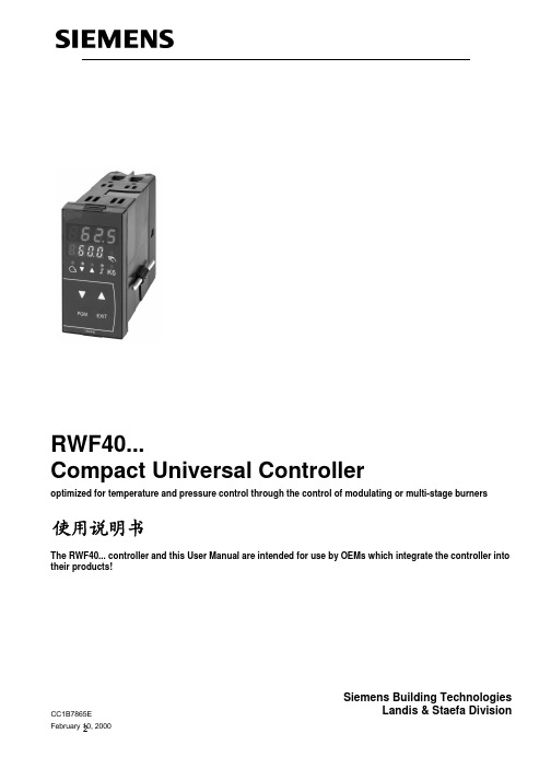
RWF40...Compact Universal Controlleroptimized for temperature and pressure control through the control of modulating or multi-stage burnersUser Manual The RWF40... controller and this User Manual are intended for use by OEMs which integrate the controller into their products!CC1B7865E February 10, 2000Siemens Building TechnologiesLandis & Staefa Division2使用说明书2/56CC1B7865E February 10, 2000Landis & Staefa Division目录11. 1.2 1.3 1.3.1 1.3.2 1.3.3233.1 3.2 3.3 3.4 3.5 3.644.1 4.2 4.3 4.455.1 5.2 5.2.1 5.2.2 5.2.3 5.2.4 5.3 5.4 5.4.1 5.4.2 5.4.3 5.4.4 5.5 5.5.1 5.6 5.7简介 (6)提示 (6)概述 (6)图形 (7)警告 (7)注意 (7)键面 (7)型号 (8)安装 (9)安装位置和气候条件 (9)尺寸 (9)并排安装 (10)安装在面板开孔中 (10)清洁面板 (11)拆下控制件 (11)电气连接 (12)安装备忘 (12)程序图 (13)端子说明 (14)分项描述 (17)工作模式 (18)低火位操作 (18)高火位操作 (18)比例调节燃烧器3位输出 (18)比例调节燃烧器比例输出 (19)两段燃烧器3位输出 (19)两段燃烧器比例输出 (20)安全锁定 (20)预界定设定点 (20)SP1/SP2设定点转换 (21)SP1/外部设定点转换 (22)SP1模拟量/二位设定点偏移 (23)外部设定二位设定偏移 (24)环境温度设定点偏移 (25)加热曲线斜率 (26)逻辑门Q响应 (27)冷启动功能 (28)36.1 6.1.1 6.2 6.2.1 6.2.2 6.2.3 6.2.4 6.2.5 6.3 6.3.1 6.4 6.4.1788.1 8.2 8.3 8.3.1 8.3.2 8.3.3 8.3.4 8.3.5 8.3.6 8.3.7 8.3.8 8.3.9 8.3.1099.1 9.210 10.1显示 (30)按键说明 (30)用户权限 (31)改变设定 (31)手动操作比例燃烧器 (33)手动操作二段燃烧器 (33)起动自设定 (34)显示软件版本和实测值单位 (34)参数等级 (35)进入参数设定 (35)初始化权限 (35)改变初始编码 (35)参数设定 (36)初始化 (38)C111 参数输入 (38)C112精密限位仪控制器型号设定点SP1锁定.40 C113寻址单位输出范围 (44)SCL 标定标准信号起始位模拟量输入1 (45)SCH 标定标准信号结束位模拟量输入1 (45)SCL2标定标准信号起始位模拟量输入2 (45)SCH2标定标准结束位模拟量输入2 (46)SPL限定最低设定点 (46)SPH限定最高设定点 (46)OFF1数值校正,模拟量输入1 (46)OFF2数值校正,模拟量输入2 (46)OFF3数值校正,模拟量输入3 (46)dF12nd数字滤波,模拟量输入1 (46)自设定功能 (47)高位火自设定功能 (47)检查控制参数 (49)故障排除 (50)数字在显示屏上闪烁 (50)411.1 11.1.1 11.1.2 11.1.3 11.1.4 11.1.5 112 11.2.1 11.2.2 11.2.3 11.2.4 11.2.5 11.2.6 11.3 11.3.1 11.3.2 11.3.31212.1 12.2 12.3输入 (51)模拟量输入1真值 (51)模拟量输入2外部设定设定点偏移 (51)模拟量输入3外部温度 (52)二进位输入D1 (52)二进位输入D2 (52)输出 (52)输出1释放燃烧器 (52)输出233位输出 (52)输出4精密限位仪 (52)输出5 比例输出可选 (53)可供直流电源 (53)界面RS 485可选 (53)概述 (53)测量精度 (54)实测值监测 (54)环境 (54)数据设定 (55)过程参数 (55)参数权限 (55)初始化权限 (56)561.1 提示使用前请阅读手册手册置于任何使用者能查找的地方请帮助我们完善手册欢迎给出建议所有设定要求内部设定均描述于手册中控制器软件编号126.01.016.2.5章显示软件版本和单位调试中任何难题不应作任何未授权的改变这将损害你的权利请联系我们归还整机附件须遵守易感静电器件保护DIN EN10015标准,用合适的ESD 包装运输不接受任何由于ESD 引起的损失.ESD: 静电释放1.2 概述使用RWF40基本用于控制油\气加热装置的温度和压力.是一个没有燃烧器位置反馈的三位控制器.可通过一个外部开关实现二级控制两段火燃烧器内部控制器控制开关燃烧器,可调的罗辑门控制到高位火输出.控制 偏移控制器控制温度和压力,可设最小和最大设定点限位.带一个标准化的自设定功能拔插件可方便把控制器安装在面板上,显示屏为两组4位7段分别显示实测值(红色)和设定值(绿色).带一可设定的限位仪;可在八个限位仪中选择所需功能备选件RS-485界面可接入数字网,输出5用作比例输出和2级操作.所有连接均用螺接端子在后部连接."#71.3 图形 1.31 警告信号 这些信号表示警告和危险危险用于常严格遵守后则将伤及人. 警告可能损害设备或数据警告 可能有静电析放.1.32 注意NOTE 需特别注意REFERENCE 参考 FOOTNOT 附注 ACTION 需要动作1.3.3 键面:键面按键如图所示,符号及文本可输入,若按盘设为复合键,当前通常为文本输入键.按键组合 表示该按键需与其他信号组合即必须先按EXT 按键不放再按其他键#"!abc¹.✱✱PGMEXIT+ v2.1型号范围位置外壳贴有型号说明,型号决定工作电压外接附件型号型号说明RWF 40.000A97基本型带3位输出RWF 40.010A971RWF 40.001A97多一比例输出RWF 40.011A971RWF 40.002A97多一比例输出和RWF 40.012A971RS-485 接口1 不同的包装#必须按所标电压供电工厂设定测量值范围和模拟信号输入由工厂设定8章<<初始化>>附件RG40 转接件可换RWF32成RWF40BRAKET ARG41可把RWF40安在导轨上, 导轨符合D41 46277标准.Dummy Cover AVA10.200/109可遮盖面板开口.893.1 安装位置和气候条件-安装在没有震动灰尘和腐蚀的地点-远离电磁源如变频器高压点火变压器相对湿度95%没凝结环境温度-20 (500)储存温度: -40 (700)3.2尺寸489691,5K6PGM EXITRWF40112Panel cutout to DIN 437004592+0,6+0,843,5127,515,57865m 01e /0200103.3并排多个控制器并排安装间隙最小纵向30.5mm,水平10.5mm3.4安装在面板开孔中安装好附带的密封.必须安装密封圈使油水不能渗入.控制器插入面板开孔安装好紧因螺丝心旋紧.#✱✱3 安装3.5 清洁面板前面板可用一般清洁剂或去污剂清洁不允许用酸性液腐蚀液和磨擦性的洁具或清洁时用力按压.3.6拆下控制件控制件可从外壳拆下维护.必须遵守DIN100015Protection of electostatically sensitive devicess 任何由静电引起损坏均不被接受.同时按住上下棱纹按钮可拆下控制件.#✱安全条例:↑导线选择,安装和电气连接必须符合VDE0100<<Regulation for thecontroller of power circuits with nominal Votages below Ac1000V>>或符合当地条例.↑电气连接由具备资质人士完成.↑控制器按上允许的接触器时,必须双向电气隔离.保险↑内部限流器保护短路,外部保险不能超过1A(慢熔断),输出回路需安装保险以防超过2A电流烧熔控制接触器确点.11.2章<<输出>>↑不允许其它负荷接在控制器上干扰↑电磁干扰和标准参照<<Technical data>>第11章<<技术数据>>↑输入,输出,控制线应分别布线,不能并行布线↑感应器线,传输线,屏显线卷在一起与电源线分开,地线接到<<TE>>端子↑ <<TE>>端接到保护接地端,交叉接触面不小于线截面积,保护接地端星形联接.多个控制器地线不能串接非正确使用↑控制器不适用于有爆炸危险环境.↑控制器误设定(设定点,参数数据和权限)可导致控制器误动作直至损坏.独立的安全装置如过压释放阀,温控器/监察器应安装并由专业人士调整且符合安全条例因自设定不能检测所有控制出厂前设置的值应先检查控制器模拟量输入对地<<TE>>不超AC 30V或DC50V..见4.3电路!!!3位输入燃烧器释放1继电器N.O.连接1Pt100, Ni100, Pt1000,2外部设定点设定点更改3外部温度Pt100, Ni10003位输出限位比较4继电器N.O.连接转换器比例输出可选5比例输出DC 0...10 V, DC 1运行方式2设定点切换2继电器调节装置断开3继电器调节装置闭合界面可选仅由专业人士进行接线工作输出LED 显示端子号接线图继电器1开启燃烧器接触保护变阻 S07K275Q14 接线柱Q13 常开触点继电器2调节装置开启接触保护RC装置继电器3调节装置关闭接触保护RC装置Y1 常开触点Q 公共端Y2 常开触点继电器4限位比较接触保护变阻 S07K275K6Q 64 端子Q 63 常开触点比例输出可选DC 04…20mA02 (10V)X1+X1-X1+X1-G-G+GNDD1D2I1CBCGCATEL1NY2M1U1G1+XB6M6XU6B9M9QY1Q13Q14Q63Q64模拟量输入1(实测值)端子接线图热电偶L1M1电阻式温控器3线M1G1+l1电阻式温度表2线补偿由补偿校正(OFF1)M1G1+电流输入DC0…20mA,4…20 mAL1M1电压输入DC0...1V, 0 (10V)U1M1模拟量输入2(设定点和设定点偏移)端子接线图电阻式电位计重设校正(OFF2)XB6 是启端M6 滑动端M6 末端电流输入DC0…20 mA, 4…20 mA XB 6 M6电压输入DC0…1V, 0…10V XU 6 M6模拟量输入3 (外部温度)端子接线图电阻式温控器2线线补偿由重设校正 (OFF3)B9M92位输入端子接线图操作模式选择Ö5.2章<<高火位操作>>D1设定点偏移/转Ö5.4.1…5.4.4章节D2公共接地端GND工作电压界面端子接线图工作电压AC100…240V + 10%48…63HZL1线N中线保护接地线TE变送运行电压G+G-多媒体界面RS - 485CACBCGD1D2GND7865a12/1099L1NTE7865a18/1099G+G-+-DC 24 V / 30 mA7865a14/1099该图显示了可能存在于控制器功能的最大电位差限位比较输出4-继电器N.O.接触3位输入输入1Pt1000Ni100实测值Pt1000Ni1000热电耦或标准信号输入2外部设定点设定点改变0…1k Ω电阻或标准信号燃烧器启动 L1N 输出1-继电器N.O.接触输入3外部温度Pt1000Ni10003位输出 L1N输出2-继电器调节装置断开输出3-继电器调节装置闭合2位输入自由电位接触D1运行模式转换D2设定点改变/转换变送电源DC 24V 30 mA 短路保护运行电压 L1NAC 100…240 V ±10%48…63 Hz比例输出可选输出 5比例输出DC 0…10V DC 0…20mA4…20mA多媒体界面RS-485 可选MOD 总线协议波特率 9600接地 TE最大绝缘电压DC 50 V AC 400 V AC 4000 V低火位操作即锅炉处于低负荷输出中两位控制器控制设定点如温控器般启闭燃烧器温控器功能 此工作模式如温控器功能通过可调整的开关积分避免燃烧器频繁启动52高火位操作高火位工作即锅炉处于高负荷输出中,燃烧器一直在工作在温控器功能作用下实测值开始下降并低于开启门HYS1操作器并不即刻转到高火位操作而先计算实测值偏移量是否超过可调罗辑门Q见Ö5 6逻辑门Q响应操作模式转换-在高火位中相对于低火位工作模式更大的燃料消耗可用D1选择两段或比例调节-D1断开比例调节-D1闭合两段调节521比例调节燃烧器3位输出图例1是温控器工作模式图2是比例调节模式在高火位中3位控制器通过接触器2打开和接触器3闭合驱动执行器图3中实测值超过逻辑门HYS1时于B 点关闭燃烧器当实测值低于逻辑门HYS1时燃烧器才重新启动若积分值超过Q逻辑门在A 点转到高火位操作Ö见56章逻辑Q响应比例和两段操作:实测值在HYS1和HYS3之间W(3)522比例调节燃烧器比例输出图1是温控器工作模式图2中控制器控制可调的设定点执行器位移信号通过比例输出作为标准信号控制器必须具备此项功能可选Ö8.2章C112精密限位仪控制器型号设定点SP1锁定523两段燃烧器3位输出图1温为控器工作模式图2通过接触器2打开和接触器3关闭控制逻辑门HYS1和HYS2输出断开控制来实现2段控制图3当实测值超过逻辑门HYS3控制关闭燃烧器B 燃烧器只在实测值低于逻辑门HYS1时重新启动当逻辑门Q被超过时启动高火段控制二段火AÖ56章逻辑门Q响应"IIIW524两段燃烧器比例输出在这种控制模式中当实测值低于逻辑门HYS1同时超过逻辑门Q 时通出模拟输出X1输出一个2位信号开启两段火超过HYS2时关闭输出控制器必须具备比例控制功能可选Ö82章C112精密控制仪控制器型号设定点SP1锁定53安全锁定当感应器故障控制器无法监测锅炉温度模拟量输入1时安全锁定动作保证不过量供热外部设定模拟量输入2具备同样功能功能燃烧器关闭 3位输出关闭调节器 自设定停止 手动操作停止5.4预界定设定点可在预设定中键入数值预设设定点根据环境温度或外部接触器输入模拟量或二位信号可偏移设定点(1)X1"章端子说明章端子说明5.4.3SP1模拟量/二位设定点偏移二位输入D2Ö 4.2章端子说明5.4.4 外部设定二位设定偏移章端子说明5.5 环境温度设定点偏移连接上外部感应器,QAC22后可实现环境温度设定点偏移,设定点干SPL 和SPH 界定的范围内变量P 可设定加热曲线每一RWF 40需单独连接一个外部感应器不能并行连接加热曲线描述第7章参数设定外部温度°C炉温度设定点°C热曲线斜率2040608010012014016043.83.63.43.232.82.62.42.221.81.61.41.210.80.60.40.22017.512.5107.552.5-2.5-5-7.5-10-12.5-15-17.5-20157865d 02e /1199SPL SPH#5.5.1加热曲线斜率斜率H可用来调整设定点对外部温度的响应根据外部环境温度如图响应通常原始点设在20/20气候调节点作用由SPL 和SPH 限定范围HYS1启动燃烧器HSYS3关闭燃烧器如前所说同时由环境温度器控制Ö5.2.1章比例燃烧器3位输出Ö5.2.2章比例燃烧器比例输出H larger7865d01e/11995.6逻辑门Q响应逻辑门Q响应界定燃烧器转到高火位操作时的实测值低于转换设定点时间多长和数值多低内部数字积分仪累计响应区域Q eff =Q1+Q2+Q3仅计算低于设定点HYS1的区域积分当积分值Q eff超过设定的逻辑门Q值时启动二段火操作或3位程控器操作/比例操作-即调节仪启动当实测值到达设定值时Q eff 被置零实测值监察避免低火和高火位间频繁动作温度°Cteff5.6 冷启动功能系统长时间关闭,实测值会降低.控制器根据设定的限定值可快速响应即刻转向高火位操作.限定值如下计算:限定值=2×(HYS1-HYS3)例:工作模式比例 3位输出HYS1=-3K HYS3=+5K W=600C限定值=2×(-3-5)=-16K当实测值低于440C 时, 操作器即刻启动高火位操作功能,代替温控器工作模式.7865d20/1099WHYS1HYS3t2 x (H Y S 1 - H Y S 3)X°Cdb6 运行操作权限用PGM 键可在显示屏进到任何级如下图顶部红色显示参数值和实测值下部绿色显示参数和设定值1用PGM 键进入各参数设定当最后参数被设定后自动回复o r t i m e -o u t (a p p r o x . 30 s )7865f08e/12996 运行6.1显示通电后PWF40显示如下图显示实测值和相关的设定参数值手动操作自设定用户设定初始化都可从这操作6.1.1按键说明启动燃烧器PGM 按钮减小值设定值显示绿实测值红7865p02e/020031启动通电后显示闪烁约10秒所有显示发亮手动操作实测值显示在显示屏高端手动指示灯LED 发亮根据操作权限和不同型号设定值显示在设定范围内绿色Ö参考手动操作6.2.2章自设定功能实测值红色显示同时tunE 在设定区绿色闪烁Ö参考9.1 自设定功能在高火段操作实测值显示闪烁Ö第10章What to do if…二段操作Ö第5.2节高段火调节时间超限 30秒内若不作任何改变控制器自动回到基本显示屏幕6.2用户权限从基本显示屏中进入设定点SP1SP2/dSP可改变类比输入E2外部设定点/设定偏移和E3外部温度设定可视6.2.1改变设定改变SP1SP2或dSP*到用户权限按PGM *改变SP1按 和*到设定SP2或dSP按PGM*改变SP2或dSP 按 和*回到基本显示屏按EXIT 或停留30秒 2秒后设定值自动运用只能在相应权限内改变相应参数""PGMPGMPGMtAPGMSP.EdSPor50.010.0PGM65.065.060.370.010.0SP 1EXITSP 2EXITEXIT7865f06e/119932基本显示使用级根据代码11显示根据2位输入2-Dsp -Sp2外部温度测量值通过模拟量输入3外部设定点或设定点偏移测量值通过模拟量输入26.2.2手动操作比例燃烧器*按EXIT5秒手形位置上的显示灯LED点亮3位控制器*改变控制单元位置按和按住接触器2打开调节器按住接触器3闭合调节器OPEN 和CLOSE 动作时调节器指示LEDs 显示比例控制器*改变控制单元位置按和比例输出驱动控制单元位移*按EXIT5秒回到自动操作模式当手动操作正在运行调节单元位置被设在零位直到由按键改变其输入为止温控器模式若温控器模式设定接触器1为工作状态只有手动才能控制若温控器模式设定接触器1为不工作状态手动控制可选6.2.3 手动操作二段燃烧器*按EXIT5秒*轻按-接触器2工作接触器3不工作-输出模拟量可选DC 10 V调节单元打开*或轻按-接触器2不工作接触器3工作-输出模拟量可选OC 0 V调节单元关闭*按EXIT5秒回到自动模式若温控器模式设接触器1在手动中不工作手动操作可选""33346.2.4起动自设定*PGM+ 启动自设定*取消当tunE 停止闪动自设定停止*按确定新设参数至少按2秒在手动和温控器模式中不可能启动tunE6.2.5显示软件版本和实测值单位*按PGM+可能的单位: 0C, 0F, % (标准信号"356.3 参数等级系统起动在此设定操作权限在权限内可按PGM 进入按控制器型号不同显示不同的设定参数6.3.1 进入参数设定通过可选值进入选定参数按相应按扭变化跟随*按增加数值*按 减少数值*按PGM 确定*或者按EXIT 取消2秒后,所设值自动生效,数值仅可在相应的权限内改变Ö 第7章参数设定6.4 初始化权限用于特别调试用某些原始数值需改变如型号值等6.4.1改变初始编码*按 选择参数位置闪动*按改变参数值*按PGM 确认或按EXIT 取消Ö 第8章参数设定""参数显示在显示屏低端绿色数值显示在高端红色+9999超限1036参数显示在显示屏低端绿色数值显示在高端红色3000s-199.9章0章大火操作999.9章0章4章加热曲线斜章1+90章温度1该参数受十进制位置设定影响37Pt100Pt100Ni100Ni100Pt1000323232Nicr-Ni/k20 mA20 mA10 V1 V外部设定点外部设定点外部设定点外部设定点v外部设定点模拟量设定点偏移模拟量设定点偏移模拟量设定点偏移模拟量设定点偏移模拟量设定点偏移1K阻值电位器DC 020mADC 420mADC 010VDC 01V1K阻值电位器DC 020mADC 420mADC 010VDC 01V123456789A38模拟量输入3没功能外部感应器Pt1002线外部感应器Ni10002线外部感应器Ni10002线二位输入D2没功能设定点转变设定点偏移工厂设定Landis & Staefa Iec 751DIN 43760Landis & Staefa9031239408.2 C112精密限位仪控制器型号设定点SP1 锁定C112精密限位仪无功能1K11K21K31K41K51K61K71K81K71K81K71K8控制器型号3位控制器比例控制器DC020mA 比例控制器DC420mA 比例控制器DC010V SP1设定SP1按纽设定SP1外部感应器设定锁定无锁定初始设定锁定参数锁定按纽锁定按键锁定只能运行1次由PGM 确认动作后所有按纽均被锁住只能由工厂解锁出厂设定1位输入1位输入1位输入1位输入1位输入1位输入1位输入1位输入2位输入2位输入3位输入3位输入1012341lK1 功能 屏显功能测量值在设定点范围w内时继电器K6动作例如w=800C AL=5 HYSt= 2 见图实测值上升K6在760C 动作闭合在860C 复原断开实测值下降K6在840C 动作在940C 复原lK2功能 同1K 但继电器闭合与断开相反HYSt=积分开关边界 AL=设定点间距lK3功能 低位限制信号功能继电器动作条件为实测值设定点限定值例如W=800C AL=10 HYSt=2实测值上升K6继电器在710C 动作闭合 实测值下降K6继电器在690C 复位断开测量值Measured value Output 442IK4功能 同1K3但闭合与断开相反HYSt=积分开关AL=设定点间距Ö见第7章参数设定IK5功能 高限信号功能接触器动作条件为实测值设定点+限定值例如W=800C AL=10 HYSt=2实测值上升K6继电器在910C 断开 实测值下降K6继电器在890C 闭合IK6功能 同1K5功能但闭合与断开功能相反测量值IK7功能开关功能独立于控制设定点仅由AL 功能决定开关点功能继电器动作条件为实测值限定值例如AL=50 HYSt =2实测值上升K6在510C时闭合实测值下降K6在490C时断开IK8功能同1K7但闭合与断开相HYST=积分开关AL= 限位值Ö参看第章参数设定测量值测量值438.3 C 113 寻址单位输出范围小数位设定影响参数真值单位地址位址0位址1位址 99小数位无小数位1位小数无小数位1位小数超限信号限位仪关闭限位仪工作出厂设定ºCºCºFºF991110 ##44例SCL = 20;SCH = 100 0C0 mA(起始)对应测量值 200C设定范围-1999…+9999工厂设定08.3.2SCH 标定标准信号结束位模拟量输入1例SCH = 80; SCL = 0 0C20 mA(结束)对应测量值 800C设定范围-1999…+9999工厂设定1008.3.3SCL2标定标准信号起始位模拟量输入2例SCL2 = 200 mA(起始)对应测量值 200C如上所述设定范围-1999…+9999工厂设定045例SCL2 = 8020 mA(结束)对应测量值 800C如上所述设定范围-1999…+9999工厂设定1008.3.5SPL限定最低设定点例控制器据此最低设定点设定范围-1999…+9999工厂设定08.3.6SPH限定最高设定点例控制器据此最高设定点设定范围-1999…+9999工厂设定1008.3.7OFF1数值校正,模拟量输入1数值校正设定通过特别计算器向上或向下校正测量值,也可用于2线电阻式线补偿设定范围-1999…+9999工厂设定0例测量值2947295.3校正+0.3-0.3显示2952958.3.8OFF2数值校正,模拟量输入2设定范围-1999…+9999工厂设定08.3.9OFF3数值校正,模拟量输入3设定范围-1999…+9999工厂设定08.3.10dF12nd数字滤波,模拟量输入1设定范围0…100 s工厂设定1s469.1高位火自设定功能tunE只能在高位火和比例燃烧器模式中实现tunE自设功能出为独立软件可插入控制器中在比例调节操作模式中tunE测试控制器的响应用特制的程序来步进位移信号用一个复杂的控制程序来响应控制器并计算和储存控制数给PID或PI控制器设dt=01 tunE程序可按要求重复响应参看流程图二段程序tunE 功能在启动时用两种不同方式根据实测值与设定点运动方向自动选择反应tunE能在任何实测值运动方向上启动如果tunE动作时实测值与设定点间存在巨大距离在自设定功能阶段开关限位线就沿着波动的值来设立开关限位线被设成实测值低于设定点值启动自设定PID控制设定控制系统识别控制器控制系统启动开关范围当真值与设定值持续小幅波动时控制系统就在设定点上下小幅波动wxt7865d12e/11994748被记录下的振幅用来计算控制参数<rt. dt. Pb.1>和得出最适合控制器的真值波时间条件-比例燃烧器中的高火操作-温控功能开关1必须连续工作否则tunE功能被删除不可能找到合适的控制参数-上述振幅在自测时不能超过高位温控设定功能若需要可增加但不能超过低位温控设定点启动twx499.2 检查控制参数可用启动程序闭合控制线圈来检查设定参数是否最适当以下图示可能出现的不正确设定和改进方法例如以下是3位PID 控制器设定点改变后的图示这些调整方法能够而且运用到其它控制系统上合适的值为dt=rt/4PB 太小PB太大rt dt 太小rt dt太大最佳调整ttt7865d16/1099txwt10故障排除5010.1 …数字在显示屏上闪烁控制器不能测到正确参数值 参数值由感应器型号决定Ö11.3.2章实测值监测显示概述原因/控制器/排除红色1999显示并闪烁显示设定值输入1超高限或超低限不能测量实测值,控制器在启动时自锁看5.3自动锁定根据 1.113设定响应*检查感应器接线当外部温控器C111由输入3控制需检测时1999闪烁红色在输入3上超高或超低检测不到外部温控器设定设定点不工作*检查感应器接线当输入2( C111)需设定和需检测实测值时1999闪烁红色当输入2上超高或超低外部设定点不可测控制器初始锁定Ö5.3章安全锁定*检查感应器开路电气连接实测值值红色显示××××测定值显示屏显示绿色1999在输入2上超高或超低设定点偏移量不可测控制器初始锁定Ö5.3章安全锁定*检查感应器开路电气连接。
LG M4224C M4224F 英语监控信息屏幕说明书

ENGLISHMONITOR SIGNAGEMONITOR SIGNAGE MODELS M4224C M4224FPlease read this manual carefully before operating your set and retain it for future reference.OWNER’S MANUALAV Component RGB PC HDMI/DVIComponentRGB PC HDMI/DVI RGB PC HDMI/DVIRGB IN RGB IN RGB IN RGB INAV Component RGB PC HDMI/DVIAV Component RGB PC HDMI/DVIAUDIO (RGB/DVI)REMOTERGB INRGB OUTHDMI/DVI INRGB INRGB OUTHDMI/DVI INAUDIO (RGB/DVI)REMOTEConnect the video/audio cable as shown in the below figure and then connect the power cord (See page 7).RCA-PC Audio CableProductVCR/DVD/Set-top BoxHDMI to DVI Signal Cable (not included)VCR/DVD/Set-top BoxProductSelect an input signal.Press the INPUT button on the remote control to select the input signal.Or, press the SOURCE button on the back of the product.INPUT SETSOURCE AUTO/SETHDMI Signal Cable (not included)When connecting with a HDMI to DVI signal input cable.When connecting with a HDMI signal input cable.• Select HDMI/DVIInput AVComponent RGB PC HDMI/DVI-HDMI Supports High Definition input and HDCP (High-bandwidth Digital Content Protection). Some devices require HDCP in order to display HD signals.Note : Dolby Digital is not supported.HDMI Input (480p/576p/720p/1080i/1080p)AVComponentRGB PCHDMI/DVI This is where the unit receives signals from the remote control.VividStandardMENUToggles between screen presets.: Select this option to display with a sharp image.Standard: The most general and natural screen display status.MENUBacklight: To control the brightness of the screen,adjust the brightness of LCD panel.Contrast : Adjust the difference between the light and dark levels in the picture.CoolMediumWarmUser Color Settings: Slightly purplish white. Medium: Slightly bluish white.Red / Green / BlueSet your own color levels.Gamma: Set your own gamma value. : -50/0/50On the monitor, high gamma values display whitish images and low gammavalues display high contrast images.16:9Original Widescreen mode.Adjust the screen video.PictureAuto Config. (RGB PC input only) : This button is for the automatic adjustment of the screen position, clock and phase. This function is available for analog signals only.If the picture isn't clear after auto adjustment and characters are stillClear VoiceStandardMusicClear Voice: By differentiating the human sound range from others,it helps users listen to human voices better.Standard: The most commanding and natural audio.To adjust uneven sound volumes across all channels or signals automatically to the mostIf the current time is incorrect, reset the clock manually.1) Press the MENU2) Press thePower SavingOffLevel 1This screen brightness adjusting menu helps you save energy. Level: Total 4 screen brightness levels are provided.To choose the language in which the control names are displayed. Use the buttons to selectTile mode and choose Tile alignment and set the ID of the current product to set location.Tile ModeID 1ID 2ID 3ID 4Tile mode (product 1 ~ 4) : c(2) x r(2)columnID 1ID 2ID 1ID 2ID 3ID 4ID 5ID 6ID 7ID 8ID 9ID 1ID 5ID 9ID 13ID 2ID 6ID10ID 14ID 3ID 7ID 11ID 15ID 4ID 8ID 12ID 16Adjust the horizontal size of the screen taking into account the size of the bezel.Network Select-LAN : Enables communication via Ethernet.You can assign a uniqueproducts are connected for display. Specify the number (01H~63H) using the。
斐夫液晶温控器说明书
⑩ 想要设置一个固定的温度,我们就需要分别设置最大值(H)和最小值(L)。
注意:温度锁定功能只能在所有程序都完全设定以后才能激活.
取消温度锁定功能:
①要取消这个功能,依次按“JOLLY”键、L1+和L2+大约10秒钟,显示器上将会 显示信息"UT OT"
②按住“JOLLY”键3秒钟,信息"UT OT"将会在显示器上闪动4次,温度锁定将 会被取消.所有设置的温度界限将会被取消.
感谢您对我们产品的信任和购买,我们真诚的建议您能仔细阅读我们的产品说明书。它 包含了产品所有必要的技术特性,以及正确安装和使用此温控器的有效信息。
由于技术和材料的不断提高,如果没有超前的意识,我们产品的规格和使用也会赶不 上日新月异的变化。
警告! 为了将来也能够参阅此书,请将说明书放置于干燥处,以防毁坏。 键: ① 数字时钟显示器
⑩ 提前编程(滚动)选择键
⑾当前时间调节(滚动选择)键 h(用笔摁住此键选择时间)
⑿当前日期调节(推动选择)键 d(用笔摁住此键选择 日期)
⒀供暖/温度调节操作开关
⒁”Jolly”高级功能键
⒂跨接线
(I)= 推动选择
(S)= 滚动选择
安装和使用说明
这种有着精美外观的温控器可以根据不同需求搭配各种各样颜色的门,使之显现出独 特的个性。
置不同的时间段并且我们使固定线出现在L1的温度里而不是L2的温度里。
⑨ 我们住 PROG DAY 键)由此类 推,周三、周四……都可以用这样的方法复制程序。
⑩ 另外,如果要求每一天的程序都不同的话,按住 PROG DAY 键选择需要日期,根据需 求编程。
② 温度设置键(confort L1) ③ 温度设置键(Risparmio L2) ④盖 ⑤ 电池盒盖 ⑥ 自动/手动/关闭按钮 ⑦ 选择(推动选择)/编程输入温度值键 confort L1 ⑧ 选择(滚动选择)/编程输入温度值键 Risparmio L2
液晶风淋控制器F4H中英文说明书
语音风淋室说明书一. 概述风淋室自控系统主要用于风淋室、货淋室及风淋通道的自动控制。
可自动实现内、外门的互锁与解锁;照明的启停;人体自动感应以及风机的启停等功能。
产品在自动流程时有相关语音提示,并具有风淋时间、前后门解锁延时时间、照明延时间可调等灵活功能。
二.主板面膜示意图及按键说明液晶语音风淋室控制器,图文界面,可与PLC相媲美,具有强大的功能,可随时进入系统改变参数,以满足客户的需要,语音系统有中文、英文二种可选用。
LCD voice air shower controller,graphic interface,can be comparable with PLC,With a powerful function, can be entered at any time to change the parameters of the system to meet the needs of customers, the voice system has two kinds of Chinese and English can be selected.面板功能说明:Touch screen function description(一)、面板示意图(1). Touch screen sketch map(二)、面板按键(2). Panel keyPower ON/OFF电源键:开启/关闭系统Light ON/OFF照明键:开启/关闭照明/ 退出键Lighting key:Turn on / off lighting/Exit keyClean ON风淋键:手动开启风淋/ 确认键Showering key:Manual opening air shower/Confirm key+PB 1、设定时间参数(增量)增量键:2、选择模式(上移)UP key: 1.Setting Times.2.Select mode.-PB 1、设定时间参数(减量)减量键:2、选择模式(下移)DOWN key: 1.Setting Times.2.Select mode.RESET复位键:紧急情况使用Emergency stop key:Emergency use(三)、图标示意图(四)、参数设置(4).Parameter setting在控制面板上同时按住键和键5秒后,进入系统设置参数。
志高风冷冷热水模块机组控制器说明书
编制XXX校对XXX审核XXX批准XXX 日期06、9、8日期2006.09.12日期2006.09.12日期2006-9-12广东志高商用空调事业本部第一部分手操器操作说明一、作面板示意图二、显示界面组成及层次:1.显示界面的组成:1.1开机显示“欢迎”界面1.2主工作界面1.3系统功能选择界面1.3.1运行管理a)机组运行设定b)设置系统日期时间c)定时功能设置1.3.2状态查询a)运行状态及检测温度查询b)故障状态查询c)故障记录查询1.3.3系统参数设置a)地址设置b)参数设置1.3.4制造商参数设置a)设置初次开机密码b)设置一级限时运行c)设置二级限时运行2.显示界面的层次图运行指示灯定时指示灯故障指示灯态查询录查询三、“欢迎”界面1.界面示意图:2.界面说明:显示生产厂家信息。
3.界面操作:开机即进入“欢迎”界面,按“菜单”键进入主工作界面。
或显示30秒后自动进入主工作界面。
四、主工作界面1.界面示意图:2.界面说明:2.1首行显示当前年份、日期、星期和时间。
2.2实时显示系统总进水温度、温度设定值、系统总出水温度、环境温度,工作模式和负荷量。
2.3负荷量的计算方法:正在运行的压机数/所有模块的压机总数×100。
不显示小数,小数部分四舍五入。
2.4显示辅热状态:3.界面操作:�按“菜单”键进入系统功能选择界面,按“返回”键返回显示欢迎界面。
�系统没有发生锁机时,或锁机时密码错误输入次数已经超限。
若十秒内不操作任何按键(运行指示页面除外),则系统自动回到主工作画面。
否则回到需要锁机密码输入提示界面。
五、系统功能选择界面1.界面示意图:2.界面说明:系统功能选择界面包括如下菜单:2.1运行管理:运行设置及设定时钟和定时开关机时间。
2.2运行状态及故障记录查询:查询模块参数及运行状态,查询历史故障记录。
2.3系统参数设置:设置系统运行参数。
进入该页面需密码验证。
2.4制造商设置:设置限制运行条件。
SuitePRO远程式自适应温泉周暖通器说明(英文)说明书
SuitePRO® ThermostatsEnergy Savings, Room By RoomIn lodging facilities, HVAC accounts for roughly 30% of the energy usage. There’s no need to be at the mercy of guests cranking up the heat or air conditioning. It’s particularlywasteful — and expensive — when guests change the temperature setting and then leave the room for hours. SuitePRO gives you endless options, putting you back in control with multiple temperature setback choices and a variety of other energy-saving features.• H ousekeeper Setback — Train your housekeeping staff to quickly put the thermostat into Economy Setback mode by simply pressing and holding the system button.• A ctivity Sensing — If the thermostat hasn’t been touched for 4, 8, 12, 16, 20 or 24 hours, as configured during setup, it will automatically return to Economy Setback to save energy.• R emote Setback Input — You can also havean occupancy sensor wired to the remote setback inputs. An occupancy sensor can provide on-demand occupancy and can shift to the energy-saving Economy Setback mode when the room is empty.• W ireless Occupancy Solution — If running wires to an occupancy sensor is an issue, SuitePRO works seamlessly with Honeywell’s WSK-24 to provide energy savings. The Wireless Occupancy Solutiondelivers comfort by combining a door switch with an occupancy sensor to assure that the thermostat won’t shift into setback mode when a room is occupied. And by triggering the setback mode when a room is unoccupied, you’ll save on heating and cooling costs.For owners and managers of hotels, dorms, retirement facilities and other personal-stay buildings with multiple rooms, controlling heating and cooling costs is a huge challenge. Honeywell is here to help you meet these challenges day in and day out with the energy-saving SuitePRO ® thermostat.From the temperature setback options to the VersaSpeed ® fan ramp algorithm, the attractive SuitePRO gives you the control you need to maintain customer comfort while maximizing energy savings. With just a few buttons and a large, backlit display, your customers will find it easy to adjust the settings to reach the comfort level they desire. Simply put, for both you and your customers, SuitePRO is sweet.2There’s Always Room For Energy SavingsEven More OptionsWhere Comfort and Energy SavingsCome T ogether• V ersaSpeed — A Honeywell exclusive, this patent-pendingfan ramp algorithm automatically adjusts the fan to reachthe setpoint.• A uto Fan Reset — When this algorithm is enabled and thehotel guest has selected a constant fan speed, the thermostatwill reset the fan to auto after two or four hours as selectedduring setup.•S U I T E P R O®T H E R M O S TAT S3Learn MoreFor more information on the Honeywell SuitePRO thermostat, call 1-800-466-3993 or visit .67-7077 PR January 2015© 2015 Honeywell International Inc.Also Consider WebStat®Building Automation Made SimpleEnjoy energy savings and improved control throughout your facility — the main entrance, pool room, kitchen and more — with a Honeywell WebStat ® controller. WebStat allows you to step up from standalone thermostat control to the automated T7350H communicating thermostat platform without incurring any excessive cost or complexity. You’ll get standard automation features such as alarming, trending, scheduling and network accessibility, andyou’ll enjoy reduced operational savings by enabling remote monitoring, alarming, floor plan visuals andthermostat assignment privileges. Best of all, WebStat keeps control simple by allowing Internet accessibility and flexibility for assigning user privileges.Automation and Control Solutions In the U.S.: Honeywell1985 Douglas Drive North Golden Valley, MN Follow us on Twitter: @honeywellcproYouTube:@honeywellcpro。
- 1、下载文档前请自行甄别文档内容的完整性,平台不提供额外的编辑、内容补充、找答案等附加服务。
- 2、"仅部分预览"的文档,不可在线预览部分如存在完整性等问题,可反馈申请退款(可完整预览的文档不适用该条件!)。
- 3、如文档侵犯您的权益,请联系客服反馈,我们会尽快为您处理(人工客服工作时间:9:00-18:30)。
语音风淋室说明书一. 概述风淋室自控系统主要用于风淋室、货淋室及风淋通道的自动控制。
可自动实现、外门的互锁与解锁;照明的启停;人体自动感应以及风机的启停等功能。
产品在自动流程时有相关语音提示,并具有风淋时间、前后门解锁延时时间、照明延时间可调等灵活功能。
二.主板面膜示意图及按键说明液晶语音风淋室控制器,图文界面,可与PLC相媲美,具有强大的功能,可随时进入系统改变参数,以满足客户的需要,语音系统有中文、英文二种可选用。
LCD voice air shower controller,graphic interface,can be comparable with PLC,With a powerful function, can be entered at any time to change the parameters of the system to meet the needs of customers, the voice system has two kinds of Chinese and English can be selected.面板功能说明:Touch screen function description(一)、面板示意图(1). Touch screen sketch map(二)、面板按键(2). Panel keyPower ON/OFF电源键:开启/关闭系统Light ON/OFF照明键:开启/关闭照明/ 退出键Lighting key:Turn on / off lighting/Exit key Clean ON风淋键:手动开启风淋/ 确认键Showering key:Manual opening air shower/Confirm key +PB 1、设定时间参数(增量)增量键:2、选择模式(上移)UP key: 1.Setting Times.2.Select mode.-PB 1、设定时间参数(减量)减量键:2、选择模式(下移)DOWN key: 1.Setting Times.2.Select mode.RESET复位键:紧急情况使用Emergency stop key:Emergency use(三)、图标示意图(四)、参数设置(4).Parameter setting在控制面板上同时按住键和键5秒后,进入系统设置参数。
进入后,键为确认键,键为退出键,键和键为选择项目和增减数值,所有项目设置结束后,按键确认,并退出(或5秒后自动确认并退出)。
On the control panel, hold the key and key for 5 seconds as the same time to enter the system setting parameters.After entering, the key to confirm key, key for the exit key, key andkey to select items and increase or decrease value,All project settings after the end of the key to confirm, and exit (or 5 seconds after the automatic recognition and exit).风淋时间快速设置:按住键或键5秒后,快速进入“b-01”风淋时间设置,5秒后自动确认并退出。
Air shower time quick setting: hold key or key for 5 seconds, quickly enter the "b-01" air shower time set, 5 seconds after the automatic confirmation and exit.参数表Parameter table一、风淋室正常操作过程:2. Air shower normal operation process(一)、初始化自检(1). Initialize the self-inspection打开电源,面板液晶屏点亮,同时微电脑控制器做一次检测,显示当前的模式(闪烁3次),进出门是否关闭,红外探头与反光板是否对准。
如系统有故障,将在屏幕上显示代码,并语音提示。
Turn on the power, LCD display, the screen flashes 3 times, at the same time, a microcomputer controller to do a test, Is the inlet and outlet door closed? Infrared probe and reflective board is aligned. If the system is faulty, the code will be displayed on the screen, and voice prompts.(二)、正常工作状态(2).Normal working state接通电源380V(带零线),指示灯由红色变为绿色,液晶屏点亮,风淋室处于自动状态。
The 380 v power supply is connected (with zero wire),Power LED red light turns green, the screen display, air shower in the automatic state.(三)、从非洁净区进入洁净区(3). From Non clean area enter clean area手拉门(红外线连锁)Manual door (Infrared sensor interlocking)开启进门,出门自动上锁,风淋室出门指示灯为红色(30秒后,进门仍未关闭,则语音提示“请关门”,且在液晶屏上有图标闪烁),人员进入风淋室,经红外探头,关闭进门,风淋启动(0~999s可调,语音提示“风淋中,请转身”),此时进出门均上锁,指示灯均为红色,风淋倒计时结束(语音提示“风淋结束,请离开),开启出门,人员走出风淋室,出门关闭,整个过程结束。
Open the inlet door, outlet door automatic locked,air shower outlet door indicator light is red (30 seconds later, inlet door is not closed, then the voice prompts " close the door, please!" and on the screen have flashing icon) and personnel to enter the air shower, through infrared sensor, closed the inlet door, the air shower running (0 ~ 999s can be adjustable, and the voice prompt "showering, please turn"), this time inlet and outlet door was locked, indicator light red, when showering end (voice prompt "showering end, please leave), open the outlet door, personnel leave air shower, closed the outlet door, the whole process end.(四)、从洁净区退出非洁净区(4). From clean area to non clean area手拉门Manual door开启出门,进门自动上锁,风淋室进门指示灯为红色(30秒后,出门仍未关闭,语音提示“请关门”,且在液晶屏上有图标闪烁),人员进入风淋室风淋不启动,关闭出门,开启进门,走出风淋室,关闭进门,整个过程结束。
Open the outlet door, inlet door automatic locked, air shower inlet door indicator light is red (30 seconds later, outlet door is not closed, voice prompts "close the door, please!" and on the screen icon flash) an personnel to enter the air shower, air shower does not start, outlet door closed, open the inlet door, personnel leave air shower, closed the inlet door, the whole process end.(五)、连锁控制(5). Interlocking control进出门连锁控制部分,分别安装于进出门外则。
Inlet door and outlet door interlocking control part,respectively installed on the inlet and outlet door.风淋室待机时,进出门指示灯亮绿灯。
Air shower standby, inlet and outlet door indicator light is green1)开进门,出门上锁,出门指示灯亮红灯,进门指示灯亮绿灯。
1) Open the inlet door, outlet door locked, outlet door indicatorlight is red, inlet door indicator light is green.2)开出门,进门上锁,进门指示灯亮红灯,出门指示灯亮绿灯。
2) Open the outlet door, inlet door locked, inlet door indicatorlight is red, outlet door indicator light is green.3)风淋室在运转时,进、出门均锁定,指示灯亮红灯。