OSPF单区域 实验报告
实验17 OSPF单区域
OSPF单区域1 实验目的:能够在单区域环境中配置OSPF路由协议。
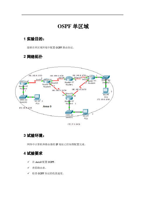
2 网络拓扑3 试验环境:网络中计算机和路由器的IP地址已经如图配置完成。
4 试验要求✓在Area0配置OSPF。
✓查看路由表。
✓检查OSPF协议的收敛速度。
5 基本配置步骤5.1在Router2上Router>enRouter#config tEnter configuration commands, one per line. End with CNTL/Z.Router(config)#router ospf 1Router(config-router)#network 192.168.0.0 0.0.0.3 area 0Router(config-router)#network 172.16.0.0 0.0.255.255 area 0Router(config-router)#ORRouter(config)#router ospf 1Router(config-router)#network 192.168.0.1 0.0.0.0 area 0Router(config-router)#network 172.16.0.1 0.0.0.0 area 0Router(config-router)#5.2在Route0上Router>enRouter#config tEnter configuration commands, one per line. End with CNTL/Z.Router(config)#router ospf 1Router(config-router)#network 192.168.0.0 0.0.0.3 area 0Router(config-router)#network 192.168.0.4 0.0.0.3 area 0Router(config-router)#network 192.168.0.12 0.0.0.3 area 0Router(config-router)#ex5.3在Router1上Router>enRouter#config tEnter configuration commands, one per line. End with CNTL/Z.Router(config)#router ospf 1Router(config-router)#network 192.168.0.0 0.0.0.255 area 05.4在Router4上Router>enRouter#config tEnter configuration commands, one per line. End with CNTL/Z.Router(config)#router ospf 1Router(config-router)#network 192.168.0.0 0.0.0.255 area 0Router(config-router)#network 172.18.0.0 0.0.255.255 area 05.5在Router3上Router>enRouter#config tRouter(config)#router ospf 1Router(config-router)#network 192.168.0.0 0.0.0.255 area 0Router(config-router)#network 172.17.0.0 0.0.255.255 area 0Router(config-router)#6 检查路由表6.1在Router3上Router#show ip routeCodes: C - connected, S - static, I - IGRP, R - RIP, M - mobile, B - BGPD - EIGRP, EX - EIGRP external, O - OSPF, IA - OSPF inter areaN1 - OSPF NSSA external type 1, N2 - OSPF NSSA external type 2E1 - OSPF external type 1, E2 - OSPF external type 2, E - EGPi - IS-IS, L1 - IS-IS level-1, L2 - IS-IS level-2, ia - IS-IS inter area* - candidate default, U - per-user static route, o - ODRP - periodic downloaded static routeGateway of last resort is not setO 172.16.0.0/16 [110/1563] via 192.168.0.13, 00:01:15, Serial2/0C 172.17.0.0/16 is directly connected, FastEthernet0/0O 172.18.0.0/16 [110/782] via 192.168.0.17, 00:01:15, Serial3/0192.168.0.0/30 is subnetted, 5 subnetsO 192.168.0.0 [110/1562] via 192.168.0.13, 00:01:15, Serial2/0O 192.168.0.4 [110/1562] via 192.168.0.13, 00:01:15, Serial2/0O 192.168.0.8 [110/1562] via 192.168.0.17, 00:01:15, Serial3/0C 192.168.0.12 is directly connected, Serial2/0C 192.168.0.16 is directly connected, Serial3/0Router#6.2查看OSPF邻居Router#show ip ospf neighborNeighbor ID Pri State Dead Time Address Interface 192.168.0.13 1 FULL/- 00:00:39 192.168.0.13 Serial2/0 192.168.0.17 1 FULL/- 00:00:35 192.168.0.17 Serial3/0 Router#6.3查看OSPF数据Router#show ip ospf databaseOSPF Router with ID (192.168.0.18) (Process ID 1)Router Link States (Area 0)Link ID ADV Router Age Seq# Checksum Link count192.168.0.1 192.168.0.1 673 0x80000005 0x0082b6 3 192.168.0.9 192.168.0.9 317 0x80000004 0x004015 4 192.168.0.17 192.168.0.17 219 0x80000005 0x00dc82 5 192.168.0.13 192.168.0.13 214 0x80000006 0x00fbd0 6 192.168.0.18 192.168.0.18 200 0x80000005 0x0093be 5 7 测试OSPF收敛速度7.1在PC0上PC>tracert 172.17.0.2Tracing route to 172.17.0.2 over a maximum of 30 hops:1 6 ms 8 ms 7 ms 172.16.0.12 12 ms 11 ms 11 ms 192.168.0.23 13 ms 18 ms 15 ms 192.168.0.144 25 ms 28 ms 29 ms 172.17.0.2Trace complete.PC>可以看到数据包是通过Router2→Router0→Router37.2在Router3上Router>enRouter#conf tEnter configuration commands, one per line. End with CNTL/Z.Router(config)#interface serial 2/0Router(config-if)#shutdown7.3在PC0上PC>tracert 172.17.0.2Tracing route to 172.17.0.2 over a maximum of 30 hops:1 9 ms 6 ms 7 ms 172.16.0.12 15 ms 11 ms 13 ms 192.168.0.23 14 ms 14 ms 16 ms 192.168.0.64 19 ms 22 ms 15 ms 192.168.0.105 26 ms 25 ms 29 ms 192.168.0.186 29 ms 30 ms 36 ms 172.17.0.2Trace complete.你可以看到数据包途径Router2→Router0→Router1→Router4→Router3。
实验 4 OSPF单区域配置
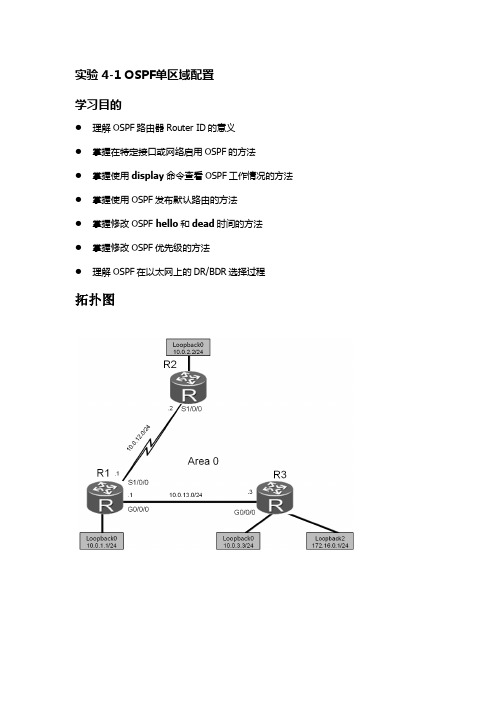
实验 4-1 OSPF单区域配置学习目的●理解OSPF路由器Router ID的意义●掌握在特定接口或网络启用OSPF的方法●掌握使用display命令查看OSPF工作情况的方法●掌握使用OSPF发布默认路由的方法●掌握修改OSPF hello和dead时间的方法●掌握修改OSPF优先级的方法●理解OSPF在以太网上的DR/BDR选择过程拓扑图场景你是公司的网络管理员。
现在公司的网络准备使用OSPF协议来进行路由信息的传递。
规划网络中所有路由器属于OSPF的区域0。
实际使用中需要向OSPF发布默认路由,此外你也希望通过这次部署了解DR/BDR选举的机制。
学习任务步骤一. 基本配置<Huawei>system-viewEnter system view, return user view with Ctrl+Z.[Huawei]sysname R1[R1]interface serial1/0/0[R1-Serial1/0/0]ip address 10.0.12.1 24[R1-Serial1/0/0]interface GigabitEthernet 0/0/0[R1-GigabitEthernet0/0/0]ip address 10.0.13.1 24[R1-GigabitEthernet0/0/0]interface loopback 0[R1-LoopBack0]ip address 10.0.1.1 24<Huawei>system-viewEnter system view, return user view with Ctrl+Z.[Huawei]sysname R2[R2]interface serial 1/0/0[R2-Serial1/0/0]ip address 10.0.12.2 24[R2-Serial1/0/0]interface loopback 0[R2-LoopBack0]ip address 10.0.2.2 24<Huawei>system-viewEnter system view, return user view with Ctrl+Z.[Huawei]sysname R3[R3]interface GigabitEthernet 0/0/0[R3-GigabitEthernet0/0/0]ip address 10.0.13.3 24[R3-GigabitEthernet0/0/0]interface loopback 0[R3-LoopBack0]ip address 10.0.3.3 24[R3-LoopBack0]interface loopback 2[R3-LoopBack2]ip address 172.16.0.1 24步骤二. OSPF配置定义R1的Loopback0接口地址10.0.1.1作为R1的Router ID,使用默认的OSPF进程号1,将10.0.12.0/24、10.0.13.0/24和10.0.1.0/24三个网段定义到OSPF区域0。
实验六:单区域OSPF配置报告
实验六:单区域OSPF配置
⏹实验目的
1、在路由器上启动OSPF路由进程
2、启用参与路由协议的接口,并且通告网络及其所在的区域
3、路由id的配置
4、DR选举的控制
5、查看和调试OSPF路由协议
⏹实验要求
本实验要达到如下要求:
1、给出具体的实现步骤
2、给出某个路由器上路由表的内容
3、给出各个网段的DR和BDR
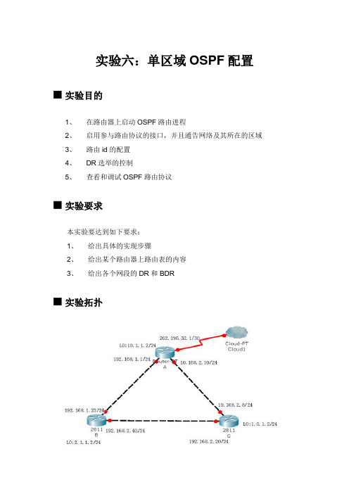
⏹实验拓扑
⏹实验设备(环境、软件)
1、路由器3台
2、交叉线3条
3、光纤1条
⏹实验设计到的基本概念和理论
给出OSPF特性、链路、链路状态、自治系统、区域的概念⏹实验过程和主要步骤
路由器A:
路由器B:
路由器C:
查看各个路由器上的路由信息:
路由器A:
路由器B:
路由器C:
查看和调试OSPF路由协议
心得体会
本次试验是进行ospf单区域的配置,本次试验的关键在于ospf协议的配置,在配置的过程中需要选定一个区域零,并把它作为主区域,然后进行命令的输入,即可达到目的。
本次试验相对来说还是比较简单的,只要我们对ospf协议配置比较熟悉,应该说还是很容易就能达到目的的。
OSPF实验
OSPF实验实验20 OSPF实验任务一:单区域OSPF基本配置步骤一:搭建实验环境并完成基本配置步骤二:检查网络连通性和路由器路由表在ClientA上ping ClientB (IP地址为10.1.0.1),结果是无法互通,导致这种结果的原因是RTA上只有直连路由,没有到达ClientB 的路由表,故从ClientA上来的数据报文无法转发给ClientB 步骤三:配置OSPF在RTA上完成OSPF如下配置:[RTA]router id 1.1.1.1[RTA]ospf 1如上配置中,数字1的含义是OSPF进程号,缺省情况下取值为1 [RTA-ospf-1]area 0.0.0.0在如下的空格中填写最恰当的配置命令[RTA-ospf-1-area-0.0.0.0]network 1.1.1.1 0.0.0.0[RTA-ospf-1-area-0.0.0.0]network 10.0.0.0 0.0.0.255[RTA-ospf-1-area-0.0.0.0]network 20.0.0.0 0.0.0.255在RTB上配置OSPF:[RTB]router id 2.2.2.2[RTB]ospf 1[RTB-ospf-1]area 0.0.0.0[RTB-ospf-1-area-0.0.0.0]network 2.2.2.2 0.0.0.0[RTB-ospf-1-area-0.0.0.0]network 10.1.0.0 0.0.0.255[RTB-ospf-1-area-0.0.0.0]network 20.0.0.0 0.0.0.255步骤四:检查路由器OSPF邻居状态及路由表在路由器上可以通过display ospf peer命令查看路由器OSPF邻居状态。
通过如上命令在RTA上查看路由器OSPF邻居状态,依据输出信息,可以看到,RTA 与Router ID为2.2.2.2(RTB)的路由器互为邻居, 此时,邻居状态达到FULL,说明RTA 和RTB之间的链路状态数据库同步,RTA具备到达RTB的路由信息。
计算机网络原理实验【OSPF单区域】

实验 5 报告 学号姓名 课堂号 01 实验日期 实验名称OSPF 单区域 实验用时 同组人指导教师 一、实验目的通过实验理解并掌握OSPF 路由选择协议的原理及配置方法,掌握使用OSPF 动态路由实现网络的连通性。
二、实验要求1.通过实验理解并掌握动态路由选择协议OSPF 的原理及配置方法,2.理解并掌握查看路由器系统及配置信息;3.掌握OSPF 路由方式实现网络的连通性。
三、实验环境(设备)实验设备路由器4台,三层交换机2台,PC4台,直连线4根,交叉线2根,V.35 DCE/DTE 电缆3根IP 地址规划,如下表: S1(C) S0 S1(C) S0 S2(C)S0 R2620-1 R2624-2 F0 S3550-1 S3550-2 F1 Area0 R2624-1 Vlan5 Vlan10 R2620-2 PC1 PC2 PC3 PC4 F0 F0设备名接口IP地址R2624-1 S0 200.20.100.1/24 S1 200.20.110.1/24 S2 200.20.120.1/24R2624-2 F0 192.168.10.2/24 F1 192.168.5.2/24 S0 200.20.120.2/24R2620-1 S1 200.20.100.2/24 F0 200.10.10.1/24R2620-2 S0 200.20.110.2/24 F0 200.10.100.1/24S3550-1 VLAN 5 192.168.5.1/24S3550-2 VLAN 10 192.168.10.1/241、单击一个路由设备如:R2624-1/2 (4口) R2620-1/2(1口)用ctrl+C中断要你输入的内容,进入Red-Giant>2、路由器R2624-1配置(1)配置R2624-1的串口s0,s1和s2R2624-1(config)#interface serial 0R2624-1(config-if)#ip address 200.20.100.1 255.255.255.0R2624-1(config-if)#no shutdownR2624-1(config)#interface serial 1R2624-1(config-if)#ip address 200.20.110.1 255.255.255.0R2624-1(config-if)#clock rate 64000(配置时钟,注意是DCE端)R2624-1(config-if)#no shutdownR2624-1(config)#interface serial 2R2624-1(config-if)#ip address 200.20.120.1 255.255.255.0R2624-1(config-if)#clock rate 64000(配置时钟,注意是DCE端)R2624-1(config-if)#no shutdown(2)验证路由器接口及串口配置:R2624-1#Show ip interface brief(3)配置ospf路由R2624-1(config)#router ospf 100R2624-1(config-osp)f#network 200.20.100.0 0.0.0.255 area 0 R2624-1(config-osp)f#network 200.20.110.0 0.0.0.255 area 0 R2624-1(config-osp)f#network 200.20.120.0 0.0.0.255 area 0 R2624-1#show ip route(查看路由)3、路由器R2624-2配置(1)配置2624-2的串口s0配置2624-2的串口s0R2624-2(config)#interface serial 0R2624-2(config-if)#ip address 200.20.120.2 255.255.255.0R2624-2(config-if)#no shutdown(2)配置以太网接口F0和f1R2624-2(config)#interface f0R2624-2(config-if)#ip address 192.168.10.2 255.255.255.0R2624-2(config-if)#no shutdownR2624-2(config)#interface f1R2624-2(config-if)#ip address 192.168.5.2 255.255.255.0R2624-2(config-if)#no shutdown(4)配置ospf路由R2624-2(config)#router ospf 100R2624-2(config-osp)f#network 192.168.10.0 0.0.0.255 area 0R2624-2(config-osp)f#network 192.168.5.0 0.0.0.255 area 0R2624-2(config-osp)f#network 200.20.120.0 0.0.0.255 area 0R2624-2#show ip route(查看路由)4、路由器R2620-1配置R2620-1>enableR2620-1#conf terEnter configuration commands, one per line. End with CNTL/Z. R2620-1(config)#hostname R2620-1R2620-1(config)#(1)查看路由器接口状态R2620-1#show ip int brief(2)配置接口f0R2620-1#conf terEnter configuration commands, one per line. End with CNTL/Z. R2620-1(config)#interface fa 0R2620-1(config-if)#ip address 200.10.10.1 255.255.255.0R2620-1(config-if)#no shutdown(3)配置串口s1R2620-1(config)#inter serial 1R2620-1(config-if)#ip address 200.20.100.2 255.255.255.0R2620-1(config-if)#clock rate 64000(配置时钟,注意是DCE端)R2620-1(config-if)#no shutdown(4)验证接口、串口配置R2620-1#Show ip interface brief(5)ospf配置R2620-1(config)#router ospf 100R2620-1(config-ospf)#network 200.10.10.0 0.0.0.255 area 0R2620-1(config-ospf)#network 200.20.100.0 0.0.0.255 area 05、路由器R2620-2配置R2620-2>enableR2620-2#conf terEnter configuration commands, one per line. End with CNTL/Z. R2620-2(config)#hostname R2620-2R2620-2(config)#(1)查看路由器接口状态R2620-2#show ip int brief(2)配置接口f0R2620-2#conf terEnter configuration commands, one per line. End with CNTL/Z. R2620-2(config)#interface fa 0R2620-2(config-if)#ip address 200.10.100.1 255.255.255.0R2620-2(config-if)#no shutdown(3)配置串口s0R2620-2(config)#inter serial 0R2620-2(config-if)#ip address 200.20.110.2 255.255.255.0R2620-2(config-if)#no shutdown(4)验证接口、串口配置R2620-2#Show ip interface brief(5)ospf配置R2620-1(config)#router ospf 100R2620-1(config-ospf)#network 200.10.100.0 0.0.0.255 area 0R2620-1(config-ospf)#network 200.20.110.0 0.0.0.255 area 06、配置S3550-1S3550-1#conf tS3550-1(config)#vlan 5S3550-1(config-vlan)#exitS3550-1(config)#interface renge f 0/10-15S3550-1(config-if-range)#switchport access vlan 5S3550-1(config)#interface vlan 5S3550-1(config-if)#ip address 192.168.5.1 255.255.255.0S3550-1(config-if)#no shutdownS3550-1(config)#router ospfS3550-1(config-ospf)#network 192.168.5.1 0.0.0.255 area 07、配置S3550-2S3550-2#conf tS3550-2(config)#vlan 10S3550-2(config-vlan)#exitS3550-2(config)#interface renge f 0/10-15S3550-2(config-if-range)#switchport access vlan 10S3550-2(config)#interface vlan 10S3550-2(config-if)#ip address 192.168.10.1 255.255.255.0S3550-2(config-if)#no shutdownS3550-2(config)#router ospfS3550-2(config-ospf)#network 192.168.10.1 0.0.0.255 area 08、测试•断开防火墙•断开第1块网卡连接•将PC1的内网卡 IP设置成192.168.5.20,掩码255.255.255.0 网关192.168.5.1 •将PC2的内网卡 IP设置成192.168.10.2,掩码255.255.255.0网关192.168.10.1 •将PC3的内网卡 IP设置成200.10.10.10,掩码255.255.255.0网关200.10.10.1 •将PC4的内网卡 IP设置成200.10.100.10,掩码255.255.255.0网关200.10.100.1 (请注意:R2620和主机之间的连接需要使用交叉线)•测试互通性附录:可使用的验证命令1.show run2.show ip interface brife3.show ip route4.Show ip ospf5.Show ip ospf border-routers6.Show ip ospf interface7.Show ip ospf neighbor五、实验记录在完成相应的配置后,以下是所有设备的路由信息【S3550-1】s3550-1>en 14Password:s3550-1#show ip routeType: C - connected, S - static, R - RIP, O - OSPF, IA - OSPF inter areaN1 - OSPF NSSA external type 1, N2 - OSPF NSSA external type 2E1 - OSPF external type 1, E2 - OSPF external type 2Type Destination IP Next hop Interface Distance Metric Status---- ------------------ --------------- --------- -------- -------- --------C 192.168.5.0/24 0.0.0.0 VL5 0 0 ActiveO 192.168.10.0/24 192.168.5.2 VL5 110 2 ActiveO 200.10.10.0/24 192.168.5.2 VL5 110 98 ActiveO 200.10.100.0/24 192.168.5.2 VL5 110 98 ActiveO 200.20.100.0/24 192.168.5.2 VL5 110 97 ActiveO 200.20.110.0/24 192.168.5.2 VL5 110 97 ActiveO 200.20.120.0/24 192.168.5.2 VL5 110 49 Actives3550-1#******************************************************************************** 【S3550-2】s3550-2#show ip routeType: C - connected, S - static, R - RIP, O - OSPF, IA - OSPF inter areaN1 - OSPF NSSA external type 1, N2 - OSPF NSSA external type 2E1 - OSPF external type 1, E2 - OSPF external type 2Type Destination IP Next hop Interface Distance Metric Status---- ------------------ --------------- --------- -------- -------- --------O 192.168.5.0/24 192.168.10.5 VL10 110 2 ActiveC 192.168.10.0/24 0.0.0.0 VL10 0 0 ActiveO 200.10.10.0/24 192.168.10.5 VL10 110 98 ActiveO 200.10.100.0/24 192.168.10.5 VL10 110 98 ActiveO 200.20.100.0/24 192.168.10.5 VL10 110 97 ActiveO 200.20.110.0/24 192.168.10.5 VL10 110 97 ActiveO 200.20.120.0/24 192.168.10.5 VL10 110 49 Actives3550-2#******************************************************************************** ******************************************************************************** 【R2624-1】r2624-1>enr2624-1#show ip routeCodes: C - connected, S - static, R - RIPO - OSPF, IA - OSPF inter areaE1 - OSPF external type 1, E2 - OSPF external type 2Gateway of last resort is not setO 192.168.10.0/24 [110/870] via 200.20.120.2, 00:06:06, Serial2O 192.168.5.0/24 [110/870] via 200.20.120.2, 00:06:06, Serial2C 200.20.120.0/24 is directly connected, Serial2O 200.10.100.0/24 [110/49] via 200.20.110.2, 00:06:06, Serial1C 200.20.110.0/24 is directly connected, Serial1C 200.20.100.0/24 is directly connected, Serial0O 200.10.10.0/24 [110/49] via 200.20.100.2, 00:06:06, Serial0r2624-1#******************************************************************************** 【R2624-2】r2624-2#show ip routeCodes: C - connected, S - static, R - RIPO - OSPF, IA - OSPF inter areaE1 - OSPF external type 1, E2 - OSPF external type 2Gateway of last resort is not setC 192.168.10.0/24 is directly connected, FastEthernet0C 192.168.5.0/24 is directly connected, FastEthernet1C 200.20.120.0/24 is directly connected, Serial0O 200.10.100.0/24 [110/97] via 200.20.120.1, 00:06:23, Serial0O 200.20.110.0/24 [110/96] via 200.20.120.1, 00:06:23, Serial0O 200.20.100.0/24 [110/96] via 200.20.120.1, 00:06:23, Serial0O 200.10.10.0/24 [110/97] via 200.20.120.1, 00:06:23, Serial0r2624-2#******************************************************************************** ******************************************************************************** 【2620-1】R2620-1>enR2620-1#show ip routeCodes: C - connected, S - static, R - RIPO - OSPF, IA - OSPF inter areaE1 - OSPF external type 1, E2 - OSPF external type 2Gateway of last resort is not setO 192.168.10.0/24 [110/918] via 200.20.100.1, 00:06:43, Serial1O 192.168.5.0/24 [110/918] via 200.20.100.1, 00:06:43, Serial1O 200.20.120.0/24 [110/917] via 200.20.100.1, 00:06:43, Serial1O 200.10.100.0/24 [110/97] via 200.20.100.1, 00:06:43, Serial1O 200.20.110.0/24 [110/96] via 200.20.100.1, 00:06:43, Serial1C 200.20.100.0/24 is directly connected, Serial1C 200.10.10.0/24 is directly connected, FastEthernet0R2620-1#******************************************************************************** ******************************************************************************** 【R2620-2】R2620-2#sho ip routCodes: C - connected, S - static, R - RIPO - OSPF, IA - OSPF inter areaE1 - OSPF external type 1, E2 - OSPF external type 2Gateway of last resort is not setO 192.168.10.0/24 [110/918] via 200.20.110.1, 00:07:09, Serial0 O 192.168.5.0/24 [110/918] via 200.20.110.1, 00:07:09, Serial0 O 200.20.120.0/24 [110/917] via 200.20.110.1, 00:07:09, Serial0 C 200.10.100.0/24 is directly connected, FastEthernet0C 200.20.110.0/24 is directly connected, Serial0O 200.20.100.0/24 [110/96] via 200.20.110.1, 00:07:09, Serial0 O 200.10.10.0/24 [110/97] via 200.20.110.1, 00:07:09, Serial0 R2620-2#六、实验结果及其分析以下是测试通讯是否畅通的结果,以地址为192.168.10.1为例Microsoft Windows XP [版本5.1.2600](C) 版权所有1985-2001 Microsoft Corp.C:\Documents and Settings\Administrator>ping 192.168.10.1Pinging 192.168.10.1 with 32 bytes of data:Reply from 192.168.10.1: bytes=32 time=3ms TTL=63Reply from 192.168.10.1: bytes=32 time<1ms TTL=63Reply from 192.168.10.1: bytes=32 time<1ms TTL=63Reply from 192.168.10.1: bytes=32 time<1ms TTL=63Ping statistics for 192.168.10.1:Packets: Sent = 4, Received = 4, Lost = 0 (0% loss), Approximate round trip times in milli-seconds:Minimum = 0ms, Maximum = 3ms, Average = 0msC:\Documents and Settings\Administrator>ping 192.168.10.5Pinging 192.168.10.5 with 32 bytes of data:Reply from 192.168.10.5: bytes=32 time<1ms TTL=255 Reply from 192.168.10.5: bytes=32 time<1ms TTL=255 Reply from 192.168.10.5: bytes=32 time<1ms TTL=255 Reply from 192.168.10.5: bytes=32 time<1ms TTL=255Ping statistics for 192.168.10.5:Packets: Sent = 4, Received = 4, Lost = 0 (0% loss), Approximate round trip times in milli-seconds:Minimum = 0ms, Maximum = 0ms, Average = 0msC:\Documents and Settings\Administrator>ping 192.168.5.1Pinging 192.168.5.1 with 32 bytes of data:Reply from 192.168.5.1: bytes=32 time<1ms TTL=64 Reply from 192.168.5.1: bytes=32 time<1ms TTL=64 Reply from 192.168.5.1: bytes=32 time<1ms TTL=64 Reply from 192.168.5.1: bytes=32 time<1ms TTL=64Ping statistics for 192.168.5.1:Packets: Sent = 4, Received = 4, Lost = 0 (0% loss), Approximate round trip times in milli-seconds:Minimum = 0ms, Maximum = 0ms, Average = 0msC:\Documents and Settings\Administrator>ping 192.168.5.20Pinging 192.168.5.20 with 32 bytes of data:Reply from 192.168.5.20: bytes=32 time<1ms TTL=128 Reply from 192.168.5.20: bytes=32 time<1ms TTL=128 Reply from 192.168.5.20: bytes=32 time<1ms TTL=128 Reply from 192.168.5.20: bytes=32 time<1ms TTL=128Ping statistics for 192.168.5.20:Packets: Sent = 4, Received = 4, Lost = 0 (0% loss), Approximate round trip times in milli-seconds:Minimum = 0ms, Maximum = 0ms, Average = 0msC:\Documents and Settings\Administrator>ping 200.20.120.1Pinging 200.20.120.1 with 32 bytes of data:Reply from 200.20.120.1: bytes=32 time=21ms TTL=254 Reply from 200.20.120.1: bytes=32 time=18ms TTL=254 Reply from 200.20.120.1: bytes=32 time=19ms TTL=254 Reply from 200.20.120.1: bytes=32 time=18ms TTL=254Ping statistics for 200.20.120.1:Packets: Sent = 4, Received = 4, Lost = 0 (0% loss), Approximate round trip times in milli-seconds:Minimum = 18ms, Maximum = 21ms, Average = 19msC:\Documents and Settings\Administrator>ping 200.20.110.1Pinging 200.20.110.1 with 32 bytes of data:Reply from 200.20.110.1: bytes=32 time=21ms TTL=254Reply from 200.20.110.1: bytes=32 time=19ms TTL=254 Reply from 200.20.110.1: bytes=32 time=19ms TTL=254Ping statistics for 200.20.110.1:Packets: Sent = 4, Received = 4, Lost = 0 (0% loss), Approximate round trip times in milli-seconds:Minimum = 19ms, Maximum = 21ms, Average = 19msC:\Documents and Settings\Administrator>ping 200.10.100.1Pinging 200.10.100.1 with 32 bytes of data:Reply from 200.10.100.1: bytes=32 time=44ms TTL=253 Reply from 200.10.100.1: bytes=32 time=37ms TTL=253 Reply from 200.10.100.1: bytes=32 time=37ms TTL=253 Reply from 200.10.100.1: bytes=32 time=37ms TTL=253Ping statistics for 200.10.100.1:Packets: Sent = 4, Received = 4, Lost = 0 (0% loss), Approximate round trip times in milli-seconds:Minimum = 37ms, Maximum = 44ms, Average = 38msC:\Documents and Settings\Administrator>ping 200.10.100.10Pinging 200.10.100.10 with 32 bytes of data:Reply from 200.10.100.10: bytes=32 time=37ms TTL=125 Reply from 200.10.100.10: bytes=32 time=37ms TTL=125Reply from 200.10.100.10: bytes=32 time=36ms TTL=125Ping statistics for 200.10.100.10:Packets: Sent = 4, Received = 4, Lost = 0 (0% loss), Approximate round trip times in milli-seconds:Minimum = 36ms, Maximum = 37ms, Average = 36ms C:\Documents and Settings\Administrator>ping 200.20.100.2 Pinging 200.20.100.2 with 32 bytes of data:Reply from 200.20.100.2: bytes=32 time=39ms TTL=253 Reply from 200.20.100.2: bytes=32 time=37ms TTL=253 Reply from 200.20.100.2: bytes=32 time=37ms TTL=253 Reply from 200.20.100.2: bytes=32 time=37ms TTL=253Ping statistics for 200.20.100.2:Packets: Sent = 4, Received = 4, Lost = 0 (0% loss), Approximate round trip times in milli-seconds:Minimum = 37ms, Maximum = 39ms, Average = 37ms C:\Documents and Settings\Administrator>ping 200.10.10.10 Pinging 200.10.10.10 with 32 bytes of data:Reply from 200.10.10.10: bytes=32 time=38ms TTL=125 Reply from 200.10.10.10: bytes=32 time=36ms TTL=125 Reply from 200.10.10.10: bytes=32 time=36ms TTL=125Ping statistics for 200.10.10.10:Packets: Sent = 4, Received = 4, Lost = 0 (0% loss),Approximate round trip times in milli-seconds:Minimum = 36ms, Maximum = 38ms, Average = 36ms经测试,四台主机均可以实现相互通讯。
OSPF单区域 实验报告.

实验报告课程名称网络规划与管理实验项目名称OSPF单区域班级与班级代码实验室名称(或课室)实验楼808 专业信息管理与信息系统任课教师学号:姓名:实验日期:2014 年9月25 日广东财经大学教务处制姓名实验报告成绩评语:指导教师(签名)年月日OSPE单区域实验一、【实验名称】OSPE单区域基本配置。
二、【实验目的】掌握在路由器上配置OSPE单区域。
三、【实验原理】OSPE(Open Shortest Path First,开放式最短路径优先)协议,是目前网络中应用最广泛的路由协议之一。
属于内部网关路由协议,能够适应各种规模的网络环境,是典型的链路状态(link-state)协议。
OSPE路由协议通过向全网扩散本设备的链路状态信息,使网络中每台设备最终同步一个具有全网链路状态的数据库,然后路由器采用SPF算法,以自己为根,计算到达其他网络的最短路径,最终形成全网路由信息。
OSPF属于无类路由协议,支持VLSM(变长子掩码)。
OSPE是以组播的形式进行链路状态的通告的。
在大规模的网络环境中,OSPE支持区域的划分,将网络进行合理规划。
划分区域时必须存在area0(骨干区域)。
其他区域和骨干区域直接相连,或通过虚链路的方式连接。
四、【实现功能】实现网络的互连互通,从而实现信息的共享和传递。
五、【实验设备】S3350(1台)、R1762路由器(两台)、V35线缆(1根)、交叉线或直连线(1条)六、【实验步骤与结果】步骤1基本配置。
三层交换机基本配置验证测试路由器基本配置1)路由器12)路由器2验证测试:验证路由器接口的配置和状态。
S3550配置OSPF路由器1配置OSPF路由器2配置OSPF步骤3查看验证三台路由设备的路由表,查看是否自动学习其他网段的路由信息。
步骤4测试网络的连通性。
C:\>ping 172.16.3.22 !从PC1 ping PC2七、【参考配置】八、【实验分析与结论】在这次实验中,我掌握了在路由器上配置OSPE单区域,知道了OSPE路由协议是通过向全网扩散本设备的链路状态信息,使网络中每台设备最终同步一个具有全网链路状态的数据库,然后路由器采用SPF算法,以自己为根,计算到达其他网络的最短路径,最终形成全网路由信息这个实验原理。
ospf单区域配置实验报告

ospf单区域配置实验报告一、实验名称OSPF单区域基础配置。
二、实验目的掌握在路由器上配置OSPF单区域。
三、实验原理OSPF(OpFnShortFstPathFirst,开放式最短路径优先)协议,是现在网络中应用最广泛路由协议之一。
属于内部网关路由协议,能够适应多种模网络环境,是经典链路状态(link-statF)协议。
0SPF路由协议经过向全网扩散本设备链路状态信息,使网络中每台设备最终同时一个含有全网链路状态数据库,然后路由器采取SPF算法,以自己为根,计算抵达其她网络最短路径,最终形成全网路由信息。
OSPF属于无类路由协议,支持VLSM(变长子掩码)。
OSPF是以组播形式讲行铸路状态通告。
在大规模网络环境中,0SPF支持区域划分,将网络进行合理计划。
划分区域时必需存在area0(骨干区域)。
其她区域和骨干区域直接相连或经讨虚铸路方法连接。
四、实验功效实现网络互连互通、从而实现信息共享和传输。
五、实验设备S3350(1台)、R1762路电器(两台)、V35线缆(1相)、交叉线可吉连线(1条)。
六、实验结果在这次实验中,我掌握了在路由器上配置OSPF单区域,知道了OSPF 路由协议是经过向全网扩散本设备链路状态信息,使网络中每台设备最终同时一个含有全网链路状态数据库,然后路由器采取SPF算法,以自己为根,计算抵达其她网络最短路径,最终形成全网路由信息这个实验原理。
即使在刚开始做实验时候出现了很多问题,比如说路由器和交换机之间应该怎么连线,IP地址和缺省网关没有配置正确等等,造成实验不能成功。
但以后经过同学之间相互研究和讨论以及老师耐心解答,这些问题都一一处理了,最终把实验成功做出来了、实现网络互连互通、从而实现信息共享和传输。
ospf单区域配置的实验报告
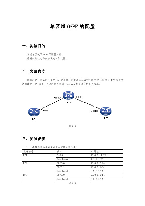
单区域OSPF的配置一、实验目的掌握单区域的OSPF的配置方法;理解链路状态路由协议的工作过程;二、实验内容实验的拓扑图如图2-1所示,要求通过配置单区域OSPF,实现RT1和RT2、RT2和RT3之间建立OSPF邻居,且互相学习到到loopback接口对应的路由信息。
图2-1三、实验步骤1.搭建实验环境并完成基本配置如表1-1。
表1-12.配置RT1的OSPF。
在RT1上启用OSPF协议,并在G0/0/0和Loopback0接口上使能OSPF,将它们加入OSPF的Area0。
[RT1] ospf 1[RT1-ospf-1] area 0[RT1-ospf-1-area-0.0.0.0] network 1.1.1.1 0.0.0.0[RT1-ospf-1-area-0.0.0.0] network 10.0.0.0 0.0.0.2553.配置RT2的OSPF。
在RT2上启用OSPF协议,并在G0/0、G0/1和Loopback0接口上使能OSPF,将它们加入OSPF的Area0。
[RT2] ospf 1[RT2-ospf-1] area 0[RT2-ospf-1-area-0.0.0.0] network 2.2.2.2 0.0.0.0[RT2-ospf-1-area-0.0.0.0] network 10.0.0.0 0.0.0.255[RT2-ospf-1-area-0.0.0.0] network 20.0.0.0 0.0.0.2554.配置RT3的OSPF。
在RT3上启用OSPF协议,并在G0/0和Loopback0接口上使能OSPF,将它们加入OSPF的Area0。
[RT3] ospf 1[RT3-ospf-1] area 0[RT3-ospf-1-area-0.0.0.0] network 3.3.3.3 0.0.0.0[RT3-ospf-1-area-0.0.0.0] network 20.0.0.0 0.0.0.255四、实验结果1.配置结束后,如图4=1所示。
- 1、下载文档前请自行甄别文档内容的完整性,平台不提供额外的编辑、内容补充、找答案等附加服务。
- 2、"仅部分预览"的文档,不可在线预览部分如存在完整性等问题,可反馈申请退款(可完整预览的文档不适用该条件!)。
- 3、如文档侵犯您的权益,请联系客服反馈,我们会尽快为您处理(人工客服工作时间:9:00-18:30)。
实验报告
课程名称网络规划与管理
实验项目名称OSPF单区域
班级与班级代码
实验室名称(或课室)实验楼808 专业信息管理与信息系统
任课教师
学号:
姓名:
实验日期:2014 年9月25 日
广东财经大学教务处制
姓名实验报告成绩
评语:
指导教师(签名)
年月日
OSPE单区域实验
一、【实验名称】
OSPE单区域基本配置。
二、【实验目的】
掌握在路由器上配置OSPE单区域。
三、【实验原理】
OSPE(Open Shortest Path First,开放式最短路径优先)协议,是目前网络中应用最广泛的路由协议之一。
属于内部网关路由协议,能够适应各种规模的网络环境,是典型的链路状态(link-state)协议。
OSPE路由协议通过向全网扩散本设备的链路状态信息,使网络中每台设备最终同步一个具有全网链路状态的数据库,然后路由器采用SPF算法,以自己为根,计算到达其他网络的最短路径,最终形成全网路由信息。
OSPF属于无类路由协议,支持VLSM(变长子掩码)。
OSPE是以组播的形式进行链路状态的通告的。
在大规模的网络环境中,OSPE支持区域的划分,将网络进行合理规划。
划分区域时必须存在area0(骨干区域)。
其他区域和骨干区域直接相连,或通过虚链路的方式连接。
四、【实现功能】
实现网络的互连互通,从而实现信息的共享和传递。
五、【实验设备】
S3350(1台)、R1762路由器(两台)、V35线缆(1根)、交叉线或直连线(1条)
六、【实验步骤与结果】
步骤1基本配置。
三层交换机基本配置
验证测试
路由器基本配置1)路由器1
2)路由器2
验证测试:验证路由器接口的配置和状态。
步骤2配置OSPF路由协议。
S3550配置OSPF
路由器1配置OSPF
路由器2配置OSPF
步骤3查看验证三台路由设备的路由表,查看是否自动学习其他网段的路由信息。
步骤4测试网络的连通性。
C:\>ping 172.16.3.22 !从PC1 ping PC2
七、【参考配置】
八、【实验分析与结论】
在这次实验中,我掌握了在路由器上配置OSPE单区域,知道了OSPE路由协议是通过向全网扩散本设备的链路状态信息,使网络中每台设备最终同步一个具有全网链路状态的数据库,然后路由器采用SPF算法,以自己为根,计算到达其他网络的最短路径,最终形成全网路由信息这个实验原理。
虽然在刚开始做实验的时候出现了很多问题,比如说路由器和交换机之间应该怎么连线,IP地址和缺省网关没有配置正确等等,导致实验不能成功。
但后来经过同学之间的相互研究和讨论,以及老师的耐心解答,这些问题都一一解决了,最终把实验成功做出来了,实现网络的互连互通,从而实现信息的共享和传递。