Agilent35670A操作手册(106)
AgilentEA仪器操作作业指导书
工艺文件产品型号:ZXC10 BTSB部件代号:BTS文件名称: Agilent E4406A仪器操作作业指导书文件编号:版本:A共 29 页(包括封面)拟制审核会签标准化批准中兴通讯股份有限公司1适用范围用于指导如何使用Agilent E4406A型(或者Agilent E4445A型)矢量信号分析仪测试ZXC10 BTSB(包括ZXC10 BTSB I1系统、ZXC10 BTSB I2系统)和ZXC10 BTSAE系统的无线指标。
2工具大功率衰减器(40dB衰减,50Ω,工作频段应满足CDMA450MHz ~频段) 1个Agilent E4406A型矢量信号分析仪(或者Agilent E4445A型)1台后台服务器(安装了ZXC10 OMC后台软件) 1台时钟电缆(BNC阳-SMB阴) 2根射频电缆(N阳-N阳,2米) 1根射频电缆(N阳-N阳,1米) 1根集线器 1个地线1根3测试方法和步骤在ZXC10 BTSB系统调试和射频的有关单板调试中,需要对系统或单板的无线指标进行测量,无线指标是否达标是衡量系统或单板是否合格的一个重要标准。
在调试中,我们采用Agilent E4406A型矢量信号分析仪对系统或单板的无线指标进行测量。
具体测试项目测试方法请按后面的说明进行操作。
3.1仪器上电前的准备工作接地:矢量信号分析仪为贵重仪器,在仪器上电之前应该保证仪器有良好的接地,以免对仪器造成不必要的损害。
在仪器的后背板的右下角有一个接地的环形接线柱,用接地电缆把仪器接地接线柱和大地良好连接起来。
外接时钟参考源:矢量信号分析仪需要外部提供PP2S和10M的参考时钟。
对于ZXC10 BTSB I1 、ZXC10 BTSB I2机架,在GCM单板的前面板上有PP2S时钟和10M时钟的输出口。
用两根时钟电缆(BNC阳-SMB阴)分别连接仪器后背板的接线柱和基站的主用GCM单板上的时钟参考源的输出口。
具体为:TRIGGER IN接线柱接ZXC10 BTSB 机架的主用GCM面板的PP2S输出口,EXT REF IN接线柱连接主用GCM面板的10M输出口。
370A测试仪操作指导书

370A测试仪操作指导书福建捷联电子有限公司编号:OPE- 30 版本:A 主题:370A测试仪操作指导书编制部门:供应商品保部文件管制:发布日期: 年月日保密等级:更新层次:起草者: 薛小华日期: 09 年 3 月 4 日审查: 日期: 年月日核准: 日期: 年月日主题:370A测试仪操作指导书文件更改记录本程序根据实际需要作如下更改,已经相关部门会签并呈报核准,签核意见及变更具体内容见附页《文件新建/更改申请单》。
主题:370A 测试仪操作指导书1.目的:确保仪器设备的正确使用及测试结果的准确性,防止仪器设备的误操作。
2.适用范围:适用于公司内所使用各类分立半导体电参数测量。
3.仪器主要功能:用于测量晶体二、三极管击穿电压、正向压降、漏电流、放大倍数等电性参数。
4.面板说明:6710主题:370A测试仪操作指导书①“OUTPUTS”开关:测试时,需将开关上拔向“ENABLED”。
测量完毕,将“OUTPUT”开关下拔置于“DISABLED”。
②电源开关。
③测试夹具的插孔。
④选择测试夹具的位置按键:如测试夹具插在左边,则按左边的按键,使之指示灯亮。
⑤电压或电流大小的微调旋钮。
⑥“CURSOR”指针按键,测试时置于“DOT”.⑦输出为曲线或点的选择键,一般置于“LONG”或“SHORT”,防止晶体管过热,引起测试损坏。
除非需要确认曲线状况,则置于“OFFSET”。
(短时间确认)。
⑧最大电压和功率量程选择键:为防止对零件的破坏,需视具体功率大小设置最大量程。
⑨输入波形选择键:视测试参数选择。
⑩波形上的测试点选择位置:若测试输出曲线时,需将曲线上的“亮点”移到曲线的最上端,以确保测试参数的正确性。
“HORIZONTAL”“VERTICAL”的刻度值旋钮。
输入“电压”或“电流”选择按钮:测试二、三极管等电流控制元件,选择为“电流”,测试MOSFET压控元件,选择为“电压”。
“STEP GENERATOR ”产生合适的STEP输出特性图.5.具体操作步骤说明:5.1开机5.1.1 检查“OUTPUTS”开关,使之置于“ENABLED”位置。
Agilent A操作说明(共16张PPT)
Agilent 34972A数据采集器操作说明
2)多路多功能复用器模块;
Agilent 34972A数据采集器操作说明
2)多路多功能复用器模块; 将导线连接到模块中如下图所示:
Agilent 34972A数据采集器操作说明
2)多路多功能复用器模块;
内部连接要求:
Agilent 34972A数据采集器操作说明
5.再按Measure键(表示确定并继续设置),再通过旋转旋扭,直到显示屏出现UNITS ℃ (度量单位为摄氏度)。 6.再按Measure键(表示确定并继续设置),再通过旋转旋扭,直到显示屏出现DISPLAY 0.1 ℃(显示精度0.1 ℃)。
7.再按Measure键,即可完成设置并退出。 其余各通道配置类似上述操作,具体步骤略。
Agilent ቤተ መጻሕፍቲ ባይዱ4972A数据采集器操作说明
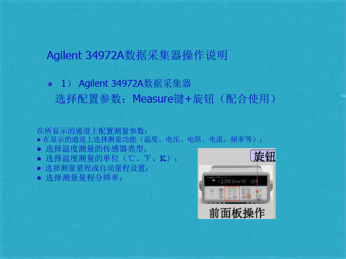
1) Agilent 34972A数据采集器
选择配置参数:Measure键+旋钮(配合使用)
在所显示的通道上配置测量参数:
● 在显示的通道上选择测量功能(温度、电压、电阻、电流、频率等);
● 选择温度测量的传感器类型; ● 选择温度测量的单位(℃、℉、K); ● 选择测量量程或自动量程设置; ● 选择测量量程分辨率;
Agilent 34972A数据采集器操作说明
其他的例图
Agilent 34972A数据采集器操作说明
停止扫描
Agilent 34972A数据采集器操作说明
导出数据
Agilent 34972A数据采集器操作说明
导出的数据结果,仅供参考!
谢谢! 2013-1-18
3) Agilent BenchLink Data Logger 3软件使用过程:
安捷伦气相色谱操作规程
安捷伦气相色谱操作规程安捷伦气相色谱操作规程1.实验室准备:1.1 检查仪器是否处于正常工作状态,包括气源系统、采样系统和检测系统。
1.2 准备好所需的色谱柱和载气瓶,并检查其是否有足够的气体。
2.仪器准备:2.1 打开色谱仪电源,并进行仪器预热。
根据实验需要,选择合适数量的柱和适当的载气。
2.2 检查色谱柱的状态,确保柱不会泄漏或损坏。
2.3 将柱连接到气相色谱仪,并确保连接紧密可靠。
2.4 打开色谱仪软件程序,并进行仪器的初始化和校准。
2.5 预先设定好实验条件,包括进样量、测量时间和温度程序。
3.样品准备:3.1 选择合适的样品,并按照样品的性质和要求进行前处理。
3.2 根据实验要求,选择合适的样品容器和进样方法,如注射器或固相微萃取技术。
3.3 将样品准备好并装入进样器或样品容器中。
4.样品进样:4.1 打开进样器,并将样品进样器与色谱仪连接。
4.2 设置进样条件,如进样量和进样速度。
4.3 按照操作手册的要求进行进样操作,包括选择进样模式和进样位置。
4.4 完成进样后,关闭进样器。
5.仪器运行:5.1 等待仪器达到平衡状态,并确保色谱柱的温度稳定。
5.2 根据实验要求,设置检测器的参数,如电流、放大倍数和检测器温度。
5.3 开始运行仪器,记录开始时间,并注意监控进样和分离过程。
5.4 在运行过程中,根据需要对仪器参数和条件进行调整,以获得最佳的分离效果。
5.5 根据需要,收集和保存分离出的化合物。
6.实验结束:6.1 在实验结束后,关闭色谱仪和进样器,并清理工作台和仪器周围的杂物。
6.2 定期对仪器进行维护和清洁工作,保持仪器的正常运行状态。
6.3 整理好实验记录和数据,制作实验报告并存档。
6.4 如果有异常情况或故障发生,及时报告并进行相应的维修和处理。
以上就是安捷伦气相色谱操作规程的简要介绍,希望对您有所帮助!。
安捷伦液相基本操作

编辑课件
24
常见色谱故障----拖尾峰
可能原因: a、柱效降低或有柱塌陷 b、进样体积过大 c、柱外扩散效应 d、碱性基质与硅羟基作用 e、重金属反应
常见色谱故障----前伸峰
可能原因: a、色谱柱过载 b、进样体积过大 c、大峰之前有未彻底分离 的小峰
编辑课件
25
常见色谱故障----负峰
可能原因: a、样品吸收比流动相吸收小 b、溶解样品的溶剂通过色谱柱平衡被破坏 c、示差检测器中最常见,溶质的折光指数小
15
工作站使用
单次样品:样品命名
编辑课件
16
工作站使用
序列样品:命名与序 列表设置
编辑课件
17
打开仪器1脱机
编辑课件
18
数据分析
数据文件夹
序列样品数据 单次样品数据
数据分析 色谱图
样品数据 色谱图编辑
编辑课件
色谱峰 数据
19
数据分析
调节积分参数
编辑课件
20
ห้องสมุดไป่ตู้
数据分析
报告→打印报告
编辑课件
21
三.常见色谱故障
编辑课件
22
常见色谱故障----基线噪音
可能原因:a、检测池脏 b、检测池灯能量下降 c、由泵引起的脉冲 d、检测器上的温度效应 e、检测其中有气泡通过
编辑课件
23
常见色谱故障----基线漂移
可能原因:a、梯度洗脱所用溶剂有吸收 b、流动相脏 c、色谱柱没有用流动相平衡 d、系统中污染物溢出 e、实验温度不稳定
编辑课件
4
2. HPLC的特点和优点
①高压:流动相为液体,流经色谱柱时,受到的阻力较大,
Agilent高效液相色谱仪标准操作程序
Agilent高效液相色谱仪标准操作程序1.目的:建立一个高效液相色谱的标准操作程序。
2.范围:适用于Agilent高效液相的使用。
3.责任:使用Agilent高效液相的化验员。
4.程序4.1工作环境实验室温度为20~27℃,温度变化<3℃/hr,相对湿度<80%,液相色谱仪工作台,长2米、宽0.8米、承重大于80公斤,离墙距离0.3米以上。
单相交流220V,(+5%~10%),50~60Hz,有单独的良好接地。
配置稳压电源,功率大于2.5千瓦。
4.2使用前的准备4.2.1二次蒸馏水,(建议用0.45微米水相滤膜过滤);甲醇或乙晴(色谱纯),(建议用0.45微米有机相滤膜过滤);其他样品所需流动相,(都需经过0.45微米滤膜过滤)。
将上述溶剂放入超声波池,除去气泡,方可使用。
4.2.2把流动相放入溶剂瓶中,打开purge阀,单击pump图标,出现参数设定菜单,单击setup选项,进入pump编辑画面,设flow:5ml/min,单击OK;单击pump图标,出现参数设定菜单,单击pump control选项,选中ON,单击OK,则系统开始purge,直到管线内(由溶剂瓶到泵入口)无气泡为止,切换通道继续purge,直到所有要用通道无气泡为止;单击pump图标,出现参数设定菜单,单击setup选项,进入pump编辑画面,设flow:1.0ml/min,关闭purge valve。
单击pump下的的瓶图标,输入溶剂的实际体积和瓶体积,也可输入阻止分析和关泵的体积,单击OK。
4.2.3进行样品前处理(稀释或溶解至所需浓度)。
4.3实验步骤4.3.1准备4.3.1.1开启Agilent 1100LC各模块电源。
4.3.1.2打开计算机,双击online图标。
4.3.1.3从"view"菜单中选择"method and run control"画面,单击"view"菜单中的"show top toolbar","show status toolbar","system diagram","sampling diagram"使其命令前有"√"标志。
Agilent气相色谱仪操作规程(2)

气相色谱仪操作规程 (1)Agilent 气相色谱仪操作规程 (9)Agilent6890N型气相色谱仪操作规程 (19)Agilent 6820 气相色谱仪标准操作规程。
(19)安捷伦7820A气相色谱仪操作规程 (22)安捷伦7890型气相色谱仪操作规程 (27)气相色谱仪操作规程1 目的:建立Agilent 6820气相色谱仪使用操作规程,保证正确使用。
2 适用范围:适用于Agilent 6820气相色谱仪的使用。
3 职责:3.1 质量控制部负责本规程的起草、审核、修订、培训和执行。
3.2 质量控制部经理负责本规程的审核和监督执行。
3.3 质量部经理负责本规程的批准。
3.4 质量保证部现场监控员负责本规程执行情况的监控。
3.5 仪器管理员负责对Agilent 6820气相色谱仪的管理。
4 定义:无5 引用标准:Agilent 6820气相色谱仪使用说明书。
6 流程图:无7 程序7.1 场地准备7.1.1 试验台空间要求气相是靠对流冷却,空气的入口在仪器的侧板和下方。
热空气从顶部、后面及侧面板上的槽孔排出。
要求上部空间一定要无障碍,仪器后面25cm的距离内无影响热空气逸散的障碍物。
7.1.2 排出有毒有害气体如果任一样品是有毒或有害的或者如果用氢气作载气,这些排放气体一定要排到通风橱里或用大管径排气管连接至室外。
7.1.3 接地线必须正确的接地以保证GC正常操作。
7.1.4 操作环境可用的温度范围:5-45℃;可用湿度范围:5%-90%(没有冷凝);海拔高度范围:最高4000m。
7.1.5 气体纯度载气和检测器气体纯度载气纯度氦气(He)氮气(N2)氢气(H2)氩气(Ar)/甲烷99.9995 %99.9995 %99.9995 %99.9995 %检测器辅助气体纯度氢气(H2)空气(干燥)99.9995 %零级或更好7.1.6 所用的载气取决于检测器的类型和性能要求推荐的载气检测器载气说明热导检测器(TCD)氦气(He)氮气(N2)氢气(H2)氩气(Ar)通用检测氢气时+最大灵敏度*检测氢气时灵敏度最大+火焰离子化检测器(FID)氦气(He)氮气(N2)可接受的替代气体最大灵敏度电子捕获检测器(ECD)氮气(N2)最大灵敏度氮磷检测器(NPD)氦气(He)氮气(N2)通用可接受的替代气体注:* 比He稍微灵敏,与某些化合物不相容。
Agilent 35670A 动态信号分析仪数据手册说明书
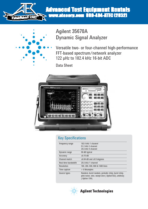
1981Agilent 35670ADynamic Signal AnalyzerVersatile two- or four-channel high-per f or m anceFFT-based spectrum/network an a l yz e r122 µHz to 102.4 kHz 16-bit ADCData SheetSummary of Features on Standard InstrumentThe following features are standard with theAgilent 35670A:Instrument modesFFT analysis Histogram/timeCorrelation analysis Time captureMeasurementFrequency domainFrequency response Power spectrumLinear spectrum CoherenceCross spectrum Power spectral densityTime domain (oscilloscope mode)Time waveform AutocorrelationC ross-correlation Orbitdiagram Amplitude domainHistogram, PDF, CDFTrace coordinatesLinear magnitude Unwrapped phaseLog magnitude Real partdB magnitude Imaginary partGroup delay Nyquist diagramPhase PolarTrace unitsY-axis amplitude: combinations of units, unit value,calculated value, and unit format describe y-axis amplitudeUnits: volts, g, meters/sec2, inches/sec2, meters/sec,inches/sec, meters, mils, inches, pascals, Kg, N, dyn, lb,user-defined EUsUnit value: rms, peak, peak-to-peakCalculated value: V, V2, V2/Hz, √Hz, V2s/Hz (ESD)Unit format: linear, dB’s with user selectable dB reference,dBm with user selectable impedance.Y-axis phase: degrees, radiansX-axis: Hz, cpm, order, seconds, user-definedDisplay formatsSingleQuadDual upper/lower tracesSmall upper and largelowerFront/back overlay tracesMeasurement stateBode diagramWaterfall display with skew, -45 to 45 degreesTrace grids on/offDisplay blankingScreen saverDisplay scalingAutoscale Selectable reference Manual Scale Linear or log X-axis Input range tracking Y-axis logX & Y scale markers with expand and scroll Marker functionsIndividual trace markersCoupled multi-trace markersAbsolute or relative markerPeak searchHarmonic markersBand markerSideband power markersWaterfall markersTime parameter markersFrequency response markersSignal averaging (FFT mode)Average types (1 to 9,999,999 averages)RMS Time exponential RMS exponential Peak holdTimeAveraging controlsOverload rejectFast averaging on/offUpdate rate selectSelect overlap process percentagePreview time recordMeasurement controlStart measurementPause/continue measurementTriggeringContinuous (Freerun)External (analog or TTL level)Internal trigger from any channelSource synchronized triggerGPIB triggerArmed triggersAutomatic/manualRPM stepTime stepPre- and post-trigger measurement Delay Tachometer input:±4 V or ±20 V range40 mv or 200 mV resolutionUp to 2048 pulses/revTach hold-off control23Data storage functionsBuilt-in 3.5 in., 1.44-Mbyte flexible disk also supports 720-KByte disks, and 2 Mbyte NVRAM disk. BothMS-DOS ® and HP-LIF formats are available. Data can be formatted as either ASCII or binary (SDF). The 35670A provides storage and recall from the internal disk, internal RAM disk, internal NVRAM disk, or external GPIB disk for any of the following information:Instrument setup states Trace dataUser-math Limit data Time capture buffers Agilent Instrument BASIC Waterfall display data Programs Data tables Curve fit/synthesis tablesGPIB capabilitiesConforms to IEEE 488.1 /488.2Conforms to SCPI 1992Controller with Agilent Instrument Basic OptionCalibration & memorySingle or automatic calibration Built-in diagnostics & service tests Nonvolatile clock with time/dateTime/date stamp on plots and saved data filesOnline helpAccess to topics via keyboard or indexFanOn/OffSource outputsRandom Burst random Periodic chirp Burst chirp Pink noise Fixed sineNote: Some source types are not available for use in optional modes. See option description for details.Input channelsManual range Anti-alias filters On/OffUp-only auto range AC or DC coupling Up/down auto range LED half range and overload indicators Floating or grounded A-weight filters On/Off Transducer power supplies (4 ma constant current)Frequency20 spans from 195 mHz to 102.4 kHz (1 channel mode)20 spans from 98 mHz to 51.2 kHz (2 channel mode)Digital zoom with 244 µHz resolution throughout the 102.4 kHz frequency bands.Resolution100, 200, 400, 800 and 1600 linesWindowsHann Uniform Flat top Force/exponentialMath+,-,*, / ConjugateMagnitude Real and imaginarySquare Root FFT, FFT -1LN EXP *jω or /jω PSD Differentiation A, B, and C weighting Integration Constants K1 thru K5 Functions F1 thru F5AnalysisLimit test with pass/failData table with tabular readout Data editingTime capture functionsCapture transient events for repeated analysis in FFT, octave, order, histogram, or correlation modes (except swept-sine). Time-captured data may be saved to internal or external disk, or transferred over GPIB. Zoom on captured data for detailed nar r ow b and analysis.Agilent 35670A Specifi cations Instrument specifications apply after 15 minutes warm-up and within 2 hours of the last self-calibration. When the internal cooling fan has been turned OFF, specifications apply within 5 minutes of the last self-cal i b ra t ion. All speci-fications are with 400 line frequency resolution and with anti-alias filters enabled unless stated otherwise.FrequencyMaximum range**1 channel mode102.4 kHz,51.2 kHz (opt AY6*)2 channel mode51.2 kHz4 channel mode (Option AY6 only) 25.6 kHzSpans1 channel mode195.3 mHz to 102.4 kHz2 channel mode97.7 mHz to 51.2 kHz 4 channel mode (Option AY6 only) 97.7 mHz to 25.6 kHz Minimimum resolution1 channel mode122 µHz (1600 linedisplay)2 channel mode61 µHz (1600 linedisplay)4 channel mode (Option AY6 only)122 µHz (800 linedisplay)Maximum real-time bandwidthFFT span for continuous data acquistion)(Preset, fast averaging)1 channel mode25.6 kHz2 channel mode12.8 kHz4 channel mode (Option AY6 only) 6.4 kHz Measurement rate(Typical) (Preset, fast averaging)1 channel mode≥ 70 averages/sec2 channel mode≥ 33 averages/sec4 channel mode (Option AY6 only)≥ 15 averages/sec Display update rateTypical (Preset, fast average off)≥ 5 updates/Sec Maximum ≥ 9 updates/Sec (Preset, fast average off, single channel, single display, undisplayed trace displays set to data registers)Accuracy±30 ppm (.003%)Single channel ampltudeAbsolute amplitude accuracy (FFT)(A combination of full scale accuracy, full scale flatness, and amplitude linearity.)±2.92% (0.25 dB) of reading±0.025% of full scaleFFT full scale accuracy at 1 kHz (0 dBfs)±0.15 dB (1.74%)FFT full scale flatness (0 dBfs) relative to 1 kHz±0.2 dB (2.33%)FFT amplitude linearity at 1 kHz measured on +27 dBVrms range with time avg, 0 to -80 dBfs±0.58% (0.05 dB) of reading±0.025% of full scaleAmplitude resolution(16 bits less 2 dB over-range) with averaging 0.0019% of full scale (typical)Residual DC response (FFT mode)Frequency display (excludes A-weight filter)<-30 dBfs or 0.5 mVdcFFT dynamic rangeSpurious free dynamic range(Includes spurs, harmonic distortion, intermodulation distortion, alias products). Excludes alias responses at extremes of span.Source impedence = 50 Ω.800 line display.90 dB typical (<-80 dBfs)* Option AY6 single channel maximum range extends to 102.4 kHz without anti-alias fi lter protection.** Show all lines mode allows display of up to 131.1, 65.5 and 32.7 kHz respectively. Amplitudes accuracy is unspecifi ed and not aliasprotected.45Full span FFT noise floor (typical)Flat top window, 64 RMS averages, 800 line display.Harmonic distortion<-80 dBfs Single Tone (in band), ≤ 0 dBfs Intermodulation distortion<-80 dBfs Two tones (in-band), each ≤ -6.02 dBfs Spurious and residual responses <-80 dBfsSource impedence = 50 Ω.Frequency alias responsesSingle tone (out of displayed range), ≤ 0 dBfs, ≤ 1 MHz(≤ 200 kHz with IEPE transducer power supply On)2.5% to 97.5% of the frequency span <-80 dBfs Lower and upper 2.5% of frequency span<-65 dBfsInput noiseInput noise levelFlat top window, -51 dBVrms range Source impedance = 50 ΩAbove 1280 Hz <-140 dBVrms/√2Hz 160 Hz to 1280 Hz <-130 dBVrms/√2Hz Note: To calculate noise as dB below full scale:Noise [dBfs] = Noise [dB/√2Hz] + 10LOG(NBW) - Range [dBVrms]; where NBW is the noise equivalent BW of the window (see below).Window parameters UniformHannFlat top-3 dB bandwidth*0.125% of span 0.185% of span 0.450% of span Noise equivalent bandwidth*0.125% of span 0.1875% of span 0.4775% of span Attenuation at ±½ bin 4.0 dB 1.5 dB 0.01 dB Shape factor(-60 dB BW/-3 dB BW)7169.12.6* For 800 line displays. With 1600, 400, 200, or 100 line displays, multiply bandwidths by 0.5, 2, 4, and 8, respectively.dB below full scaleTypical noise floor vs. range for different frequency spans-51 -41 -31 -21 -11 270.0028 0.0089 0.028 0.089 0.28022.4-100 dB/0.001%Amplitude range (dBVrms / Vrms)-90 dB/0.003%-80 dB/0.01%-70 dB/0.03%51.2 kHz Span 6.4 kHz Span 800 Hz SpanSingle channel phasePhase accuracy relative to externaltrigger± 4.0 deg16 time averages center of bin,DC coupled 0 dBfs to -50 dBfs only0 Hz < freq ≤ 10.24 kHz onlyFor Hann and flat top windows, phase is relative to a cosine wave at the center of the time record. For the uniform, force, and exponential windows, phase is relative to a cosine wave at the beginning of the time record.Cross-channel amplitudeFFT cross-channel gain accuracy± 0.04 dB (0.46%) Frequency response modeSame amplitude rangeAt full scale: Tested with 10 RMSaverages on the -11 to +27 dBVrmsranges, and 100 RMS averages onthe -51 dBVrms rangeCross-channel phaseCross-channel phase accuracy(Same conditions as cross-channelamplitude)± 0.5 degInputInput ranges (full scale)(Auto-range capability)+27 dBVrms (31.7 Vpk) to -51 dBVrms(3.99 mVpk) in 2 dB stepsMaximum input levels42 VpkInput impedance 1 MΩ ±10%90 µF nominalLow side to chassis impedance 1 MΩ ±30% (typical) Floating mode<0.010 µF Grounded mode≤100 ΩAC coupling rolloff<3 dB rolloff at 1 Hz Source impedance = 50 ΩCommon mode rejection ratioSingle tone at or below 1 kHz-51 dBVrms to -11 dBVrms ranges>75 dB typical-9 dBVrms to +9 dBVrms ranges>60 dB typical+11 dBVrms to +27 dBVrms ranges>50 dB typicalCommon mode range(floating mode)± 4 V pkIEPE transducer power supplyCurrent source 4.25 ± 1.5 mA Open circuit voltage+26 to +32 Vdc A-weight filter Type 0 tolerance Conforms to ANSI Standard S1.4-1983;and to IEC 651-1979; 10 Hz to 25.6 kHzCrosstalkBetween input channels, andsource-to-input (Receiving channelsource impedance = 50 Ω)< -135 dBbelow signal or< -80 dBfs ofreceivingchannel, which-ever responseis greater inamplitude Time domainSpecifications apply in histogram/time mode,and unfiltered time displayDC amplitude accuracy ±5.0 %fsRise time of -1 V to 0 V test pulse<11.4 µSec Settling time of -1 V to 0 V test pulse<16 µSec to 1% Peak overshoot of -1 V to 0 Vtest pulse<3% Sampling period1 channel mode 3.815 µSec to2 Sec in 2x steps2 channel mode 7.629 µSec to 4 Sec in 2x steps4 channel mode 15.26 µSec to 8 Sec in 2x steps (Option AY6 only)6TriggerTrigger modes Internal, source,external (analogsetting) GPIB Maximum trigger delayPost trigger8191 secondsPre trigger8191 sample periods No two channels can be further than±7168 samples from each other.External trigger max. input±42 VpkExternal trigger rangeLow range-2 V to +2 VHigh range-10 V to +10 V External trigger resolutionLow range15.7 mVHigh range78 mV TachometerPulses per Revolution0.5 to 2048RPM 5 ≤ RPM ≤ 491,519 RPM Accuracy±100 ppm (0.01%)(typical)Tach level rangeLow range-4 V to +4 VHigh range-20 V to +20 V Tach level resolutionLow range39 mVHigh range197 mV Maximum tach input level ±42 Vpk Minimum tach pulse width600 nSec Maximum tach pulse rate 400 kHz (typical)Source outputSource types Sine, random noise,chrip, pink noise,burst random, burstchirpAmplitude range AC: ±5 V peak*DC: ±10 V** Vacpk+ |Vdc| ≤ 10 V AC amplitude resolutionVoltage > 0.2 Vrms 2.5 mVpeak Voltage < 0.2 Vrms0.25 mVpeakDC offset accuracy±15 mV ± 3% of(|DC| + Vacpk) set-tingsPink noise adder Add 600 mV typicalwhen using pinknoiseOutput impedance< 5 ΩMaximum loadingCurrent±20 mA peak Capacitance0.01 µFSine amplitude accuracy at 1 kHz±4% (0.34 dB) ofsettingRload > 250 Ω0.1 Vpk to 5 Vpk Sine Flatness (relative to 1 kHz)±1 dB0.1 V to 5 V peak Harmonic and sub-harmonic distortion and spurious signals (In band)0.1 Vpk to 5 Vpk sine waveFundamental < 30 kHz< -60 dBc Fundamental > 30 kHz< -40 dBcDigital interfacesExternal keyboard Compatible withPC-style 101-keykeyboardGPIBConforms to the following standards:IEEE 488.1 (SH1, AH1, T6, TE0, L4, LE0, SR1, RL1,PP0, DC1, DT1, C1, C2, C3, C12, E2)EEE 488.2-1987Complies with SCPI 1992Data transfer rate(REAL 64 Format)< 45 mSec for a401 point trace Serial portParallel portExternal VGA port7Computed order tracking – Option 1D0Maximum order x Maximum RPM ( —————————————— ) ≤60Online (real time) 1 channel mode 25,600 Hz2 channel mode 12,800 Hz4 channel mode 6,400 Hz Capture playback 1 channel mode 102,400 Hz2 channel mode 51,200 Hz4 channel mode 25,600 Hz Number of orders ≤ 2005 ≤ RPM ≤ 491,519 (Maximum useable RPM is limited by resolution, tach pulse rate,pulses/revolution and average mode settings.)Delta order1/128 to 1/1Resolution ≤ 400(Maximum order)/(Delta order)Maximum RPM ramp rate 1000 RPM/second real-time(typical)1000 - 10,000 RPM run upMaximum order10Delta order0.1RPM step 30 (1 channel)60 (2 channel)120 (4 channel)Order track amplitude accuracy ±1 dB (typical)Real time octave analysis – Option 1D1StandardsConforms to ANSI Standard S1.11 - 1986, Order 3, Type 1-D,extended and optional frequency rangesConforms to IEC 651-1979 Type 0 Impulse, and ANSI S1.41 second stable averageSingle tone at band center:≤ ± 0.20 dBReadings are taken from the linear total power spectrumbin. It is derived from sum of each filter.1/3-octave dynamic range> 80 dB (typical) perANSI S1.11-19862 second stable averageTotal power limited by input noise levelFrequency ranges (at centers)Online (real time):Single channel 2 channel 4 channel1/1 octave 0.063 - 16 kHz0.063 - 8 kHz0.063 - 4 kHz1/3 octave 0.08 - 40 kHz0.08 - 20 kHz0.08 - 10 kHz1/12 octave 0.0997 -12.338 kHz0.0997 -6.169 kHz0.0997 -3.084 kHzCapture playback1/1 octave 0.063 - 16 kHz0.063 - 16 kHz0.063 - 16 kHz1/3 octave 0.08 - 31.5 kHz0.08 - 31.5 kHz0.08 - 31.5 kHz1/12 octave 0.0997 -49.35 kHz0.0997 -49.35 kHz0.0997 -49.35 kHzOne to 12 octaves can be measured and displayed.1/1-, 1/3-, and 1/12-octave true center fre q uen c ies related by theformula: f(i+1)/f(i) = 2^(1/n); n=1, 3, or 12; where 1000 Hz isthe reference for 1/1, 1/3 octave, and 1000*2^(1/24) Hz is thereference for 1/12 octave. The marker returns the ANSI standardpreferred frequencies.Swept sine measurements – Option 1D2Dynamic range130 dBT ested with 11 dBVrms source level at: 100 mSec integrationCurve fi t/synthesis – Option 1D320 Poles/20 zeroes curve filter frequency responsesynthesis pole/zero, pole residue & polynomical formatArbitrary waveform source – Option 1D4Amplitude range AC: ±5 V peak*DC: ±10 V** Vacpk+ |Vdc| ≤ 10 VRecord length# of points = 2.56 x lines ofresolution, or # of complexpoints = 1.28 x lines of resolutionDAC resolution0.2828 Vpk to 5 Vpk 2.5 mV0 Vpk to 0.2828 Vpk0.25 mV8General specifi cationsSafety standards CSA certified for electronictest and measurement equip-ment per CSA C22.2, NO.231 This product is designedfor compliance to: UL1244,Fourth Edition IEC 348, 2ndEdition, 1978EMI / RFI standards CISPR 11Acoustic power LpA < 55 dB (Cooling fan athigh speed setting)< 45 dB (Auto speed settingat 25 °C)Fan speed settings of high, automatic, and off are available. The fan off setting can be enabled for a short period of time, except at higher ambient temperatures where the fan will stay on.Environmental operating restrictionsOperating: Disk in drive Operating:No disk in driveStorage &transportAmbient temp. 4 °C to 45 °C0 °C to 55 °C-40 °C to 70 °C Relative humidity(non-condensing)Minimum20%15%5%Maximum80% at 32 °C95% at 40 °C95% at 50 °C Vibrations (5 - 500 Hz)0.6 Grms 1.5 Grms 3.41 GrmsShock 5 G (10 mSec ½ sine) 5 G (10 mSec ½ sine)40 G (3 mSec ½ sine)Max. altitude4600 meters(15,000 ft.)4600 meters(15,000 ft.)4600 meters(15,000 ft.)AC power90 Vrms - 264 Vrms(47 - 440 Hz)350 VA maximumDC power12 VDC to 28 VDC nominal200 VA maximumDC current at 12 V Standard: <10 A typical4 channel: <12 A typical Warm-up time15 minutesWeight15 kg (33 lb) net29 kg (64 lb) shippingD imensions (Excluding bail handle and impact cover) Height190 mm (7.5")Width340 mm (13.4")Depth465 mm (18.3")AbbreviationsdBVrms dB relative to 1 Volt rms.dBfs dB relative to full scale amplitude range.Full scale is approx. 2 dB below ADC overload. Typical Typical, non-warranted, performance speci-fication included to provide general productinformation.General Specifi cations9Remove all doubtOur repair and calibration services will get your equip-ment back to you, performing like new, when promised. You will get full value out of your Agilent equipment through-out its lifetime. Your equipment will be ser-viced by Agilent-trained technicians using the latest factory calibration procedures, automated repair diag-nostics a nd g enuine p arts. Y ou w ill a lways h ave t he u tmostconfi dence in your measurements. For informationregarding self maintenance of this product, pleasecontact your Agilent offi ce.Agilent offers a wide range of additional expert testand measurement services for your equipment, in-cluding initial start-up assistance, onsite educationand training, as well as design, system integration,and project management.For more information on repair and calibrationservices, go to:/fi nd/removealldoubtAgilent Email Updates/fi nd/emailupdatesGet the latest information on theproducts and applications you select.Agilent Direct/fi nd/agilentdirectQuickly choose and use your test equipment solutions with confi dence.For more information on Agilent Technologies’ products, applications or services, please contact your local Agilent office. The complete list is available at:/fi nd/contactus AmericasC anada (877) 894-4414Latin America 305 269 7500United States (800) 829-4444Asia Pacifi c Australia 1 800 629 485C hina 800 810 0189Hong Kong 800 938 693India 1 800 112 929Japan 0120 (421) 345Korea 080 769 0800Malaysia 1 800 888 848Singapore 180****8100Taiwan 0800 047 866Thailand 1 800 226 008Europe & Middle EastAustria 01 36027 71571Belgium 32 (0) 2 404 93 40 Denmark 45 70 13 15 15Finland 358 (0) 10 855 2100France 0825 010 700**0.125 €/minuteGermany 07031 464 6333Ireland 1890 924 204Israel 972-3-9288-504/544Italy 39 02 92 60 8484Netherlands 31 (0) 20 547 2111Spain 34 (91) 631 3300Sweden 0200-88 22 55Switzerland 0800 80 53 53United Kingdom 44 (0) 118 9276201Other European Countries: /fi nd/contactusRevised: October 1, 2008Product specifi cations and descriptions in this document subject to change without notice.© Agilent Technologies, Inc. 2009Printed in USA, January 9, 20095966-3064EMS-DOS is a U.S. registered trademark of Microsoft Corporation.MATLAB is a U.S. registered trademark of The Math Works, Inc. /fi nd/35670A。
- 1、下载文档前请自行甄别文档内容的完整性,平台不提供额外的编辑、内容补充、找答案等附加服务。
- 2、"仅部分预览"的文档,不可在线预览部分如存在完整性等问题,可反馈申请退款(可完整预览的文档不适用该条件!)。
- 3、如文档侵犯您的权益,请联系客服反馈,我们会尽快为您处理(人工客服工作时间:9:00-18:30)。
AGILENT 35670A频率响应分析仪使用简介
1. 频率响应的测试(SOURCE,CH1接速度环输入端,CH2接测速机信号+端)
SOURCE与CH1短连,并将一个探头与CH1连接,用于产生正弦信号激励信号。
接到速度环输入端。
CH2用于反馈信号,接到测速机信号+端。
信号的地与机壳地相连。
探头可不接地。
2. 写数据图形名称
HP3562A频率响应分析仪使用简介
1频率响应的测试(SOURCE,CH1接速度环输入端,CH2接测速机信号+端)
1.1 探头连接CH2
1.2
1.3
1.3.1
,选择正弦扫描
b. A GAIN ON OFF,选择ON
c. A GAIN SELECT 增益选择
CH1 REF,选择通道CH1为参考
REF LEVEL,设置参考电平为5-10V
,设置扫频信号源的电平门限(可根据测试情设置0.3V左右)
1.3.
2.
SOURCE LEVEL,设扫频信号源的电平幅度(可根据测试情设置0.3V左右,
不超过门限值)
SOURCE ON OFF,设置为ON
,设置为从低到高扫频(也可相反)
1.3.3.
START FREQ,起始频率
STOP FREQ ,终止频率
,扫描速率,可用旋钮S/DC
1.3.4.
1.3.5.
UNITS TRACE TITLE,输入文字最大20个
ENTER,确定
COORD MAG(db)【A】
PHAS(deg)【B】/【A&B】
1.3.6.
,开始绘图
SELECT PENS,选择绘图笔号,均选同一支笔
1.4 探头分配
SOURCE与CH1短连,并将一个探头与CH1连接,用于产生正弦信号激励信号。
CH2用于反馈信号。
信号的地与机壳地相连。
探头可不接地。
2 时间捕获的使用
时间捕获模式只能用CH1为输入通道(SOURCE 与CH1断开),类似于普通示波器。
2.1.MEASURMENT
模式选择和捕获长度输入
TIME CAPTURE….CAPTURE SELECT….CAPTURE LENGTH….10.0秒
输入时间长度
TIME LENGTH….1.0秒(CAPTURE LENGTH的十分之一)
2.2.INPUT SELECT
CHAN1 RANGE….5V(信号幅度选择)
CHAN1 DC
FLOAT CHAN1
GROUD CHAN2
TRIG LEVEL….TRIG LEVEL=.0.1V,CHAN1 INPUT,SLOP+
2.3.SELECT DATA
.TIME BUFFER
2.4.MEASURMENT
.
TIME CAPTURE….CAPTURE SELECT….START CAPTURE
2.5.SELECT DATA
X SCALE
Y SCALE
AGILENT35670A频率响应分析仪使用简介HP3562A频率响应分析仪使用简介
中国电子科技集团公司电子第39研究所106研究室
2008-08-08。